 Lapsed, fee not paid6 drawings
Materials & Chemistry · US 9,985,240 B2
Sealing material and sealing method using the same
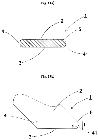
A sealing material is formed of a glass ribbon having a thickness of 1 to 100 μm.
US 9,987,608 B2 · Assignee: NANOSYNTHESIS PLUS, LTD. · Inventors: Pigos; Elena
Sheet 1 of 3 from the published document. All sheets in the USPTO PDF
Methods and apparatuses are provided for the production of homogeneous dispersions of nanostructures within a matrix, which may be used as precursors of carbon-reinforced or boron nitride-reinforced composite materials. An apparatus for producing a nanostructure dispersion comprises a reactor and a mixing chamber, wherein the reactor is configured to produce an aerosol of nanostructures and is in fluidic communication with the mixing chamber. A matrix material is provided in the mixing chamber, and the aerosol of nanostructures can disperse into the matrix material to form a nanostructure dispersion. The apparatus may further comprise a matrix tank comprising a matrix material, wherein the matrix material is transferred to the mixing chamber. An aerosol of matrix particles may be produced from the matrix material and provided in the mixing chamber, so as to produce a fine dispersion of nanostructures in the matrix. The apparatus may be configured to continuously produce a nanostructure dispersion.
Carbon nanostructures have distinct electrical, thermal and mechanical properties that are desirable for use in structural applications as well as in electrically and thermally conducting functional materials. Carbon nanostructures have been combined with matrix or other materials to provide carbon nanostructure-reinforced composite materials having enhanced properties relative to the corresponding non-composite materials. Carbon nanostructure-reinforced composite materials are being used as, amongst other things, lightweight, rigid and high-strength materials. There is a need in the art for improved methods for preparing carbon nanostructure-reinforced composite materials having these superior properties.
All 3 drawing sheets from the published document, cropped to the drawing.
What the patent claimed, word for word. All of it is now free to use.
Carbon nanostructures have distinct electrical, thermal and mechanical properties that are desirable for use in structural applications as well as in electrically and thermally conducting functional materials. Carbon nanostructures have been combined with matrix or other materials to provide carbon nanostructure-reinforced composite materials having enhanced properties relative to the corresponding non-composite materials. Carbon nanostructure-reinforced composite materials are being used as, amongst other things, lightweight, rigid and high-strength materials. There is a need in the art for improved methods for preparing carbon nanostructure-reinforced composite materials having these superior properties.
The present disclosure provides methods and apparatuses for the production of homogeneous dispersions of nanostructures within a matrix for precursors of carbon-reinforced or boron nitride-reinforced composite materials. Also provided are dispersions of nanostructures and composite materials formed from nanostructure dispersions.
In various aspects, the present disclosure provides methods for producing nanostructure dispersions. In some aspects, the methods comprise providing a reactor and a mixing chamber, wherein the reactor is in fluidic communication with the mixing chamber. In some aspects, the methods further comprise producing an aerosol of nanostructures in the reactor and providing a matrix material in the mixing chamber, wherein the matrix material may be a solid powder or a liquid. The method further comprises transferring the aerosol of nanostructures from the reactor to the mixing chamber, and dispersing the aerosol of nanostructures into the matrix material, thereby producing a nanostructure dispersion.
In some embodiments, the method may further comprise producing an aerosol of matrix particles from the matrix material, and providing the aerosol of matrix particles in the mixing chamber. The aerosol of nanostructures may then be dispersed into the aerosol of matrix particles, thereby producing a fine dispersion of nanostructures in the matrix material.
The aerosol of nanostructures may be transferred directly from the reactor to the mixing chamber. In the mixing chamber, the aerosol of nanostructures may be dispersed into the matrix material by a mechanical stirrer, a magnetic stirrer, ball miller, a sonicator, or a combination thereof. The nanostructure dispersion may be transferred to a collector, optionally as an aerosol.
In some embodiments, the method may further comprise providing a matrix tank in fluidic communication with the mixing chamber. The matrix tank can comprise the matrix material, and the matrix material may be transferred from the matrix tank to the mixing chamber. In some embodiments, the matrix material in the matrix tank may be fluidized to form an aerosol of matrix particles, prior to being transferred to the mixing chamber. The aerosol of matrix particles may be transferred to the mixing chamber by a tangential vortex, wherein the vortex is created by a tangential injection of a second carrier gas into the matrix tank.
The method may further comprise providing an injector in fluidic communication with the reactor. The injector may be used to introduce a catalyst into the reactor. The catalyst may be introduced as a liquid, spray, or aerosol, and may comprise a plurality of colloidal particles. In some embodiments, the injector may be used to introduce a catalyst precursor, a promoter, or a combination thereof, wherein the catalyst precursor may form active catalyst particles in the reactor.
The different structural elements used in the methods described herein may be arranged in various configurations. For example, the matrix tank may be positioned below the mixing chamber and above or below the reactor. The injector may be positioned above or below the reactor. The mixing chamber may be positioned above or below the reactor. The reactor and the mixing chamber may be positioned at various angles relative to one another. For example, the reactor may be positioned at any angle in the range from about 0° to about 180° relative to the mixing chamber.
The reactor may comprise a catalyst particle growth zone and a nanostructure growth zone. The reactor may produce a plurality of catalyst particles in the catalyst particle growth zone, wherein the catalyst particles may have a mean diameter in the range from about 0.5 nm to about 100 nm. The catalyst particles may comprise a transition metal, and may be supported on a catalyst support that may be the same as or different from the matrix material.
The method may further comprise introducing a carbon precursor into the reactor, wherein the carbon precursor may be decomposed to produce the aerosol of nanostructures. The carbon precursor may be mixed with a first carrier gas prior to being introduced into the reactor, wherein the first carrier gas may be an inert gas. The decomposition of the carbon precursor to produce the aerosol of nanostructures may take place at the plurality of catalyst particles produced in the catalyst particle growth zone of the reactor. The decomposition may be thermal or catalytic decomposition.
In some embodiments, the method may further comprise providing a plurality of pores through the base of the mixing chamber, introducing a second carrier gas into the mixing chamber through the pores, and producing an aerosol of matrix particles in the second carrier gas. The aerosol of matrix particles may also be produced in the mixing chamber by applying a tangential vortex to or vertically shaking the mixing chamber, or by a combination of all named ways.
The nanostructure dispersion produced by the methods described herein may be a homogeneous mixture, wherein the mixture may comprise a plurality of individual nanostructures, a plurality of non-individual nanostructures comprising a plurality of nanostructure bundles, or a combination thereof. The nanostructures may be one or more of many types of nanostructures, including carbon nanotubes and carbon fibers. The carbon nanotubes may be single-walled carbon nanotubes or multi-walled carbon nanotubes.
In some embodiments, the nanostructure dispersion may be continuously produced. In embodiments comprising a matrix tank, the method may further comprise continuously transferring the aerosol of nanostructures from the reactor to the mixing chamber, and continuously transferring the matrix material from the tank to the mixing chamber.
Aspects of the disclosure further provide a method for continuously producing a nanostructure dispersion. The method comprises providing a reactor and a mixing chamber in fluidic communication with one another, continuously producing an aerosol of nanostructures in the reactor, and continuously providing a matrix material in the mixing chamber. The method further comprises continuously transferring the aerosol of nanostructures from the reactor to the mixing chamber, and dispersing the aerosol of nanostructures into the matrix material, thereby producing a nanostructure dispersion.
In some embodiments, the method may further comprise continuously producing an aerosol of matrix particles from the matrix material, continuously providing the aerosol of matrix particles in the mixing chamber, and dispersing the aerosol of nanostructures into the matrix material comprising the aerosol of matrix particles.
The nanostructure synthesis reaction may be performed at any temperature in the range from about 200° C. to about 1600° C. The reactor may be configured to be held at two or more different temperatures. For example, the catalyst particle growth zone may be configured to be held at a temperature in the range from about 400° C. to 1000° C., and the nanostructure growth zone may be configured to be held at a temperature in the range from about 800° C. to about 1300° C. The rate of flow of the second carrier gas may be selected from about 100 sccm to about 5000 sccm. The rate of production of the aerosol of nanostructures may be held constant at a rate from about 0.1 g/hr to about 100 g/hr, while the mass percent of the nanostructures in the dispersion may be controlled modulating either the quantity of matrix material provided to the mixing chamber or the duration of the production of the aerosol of nanostructures.
Aspects of the present disclosure also provide a nanostructure dispersion produced by the methods described herein, and a composite material comprising the nanostructure dispersion produced by the methods described herein.
Aspects of the disclosure further provide an apparatus for producing a nanostructure dispersion. The apparatus comprises a reactor, an injector in fluidic communication with the reactor, a mixing chamber in fluidic communication with the reactor, a matrix tank in fluidic communication with the mixing chamber, and a collector in fluidic communication with the mixing chamber. The injector may further comprise a gas inlet for introducing a first carrier gas, and the matrix tank may further comprise a gas inlet for introducing a second carrier gas. The mixing chamber may further comprise a mechanical stirrer, a magnetic stirrer, a ball miller, a sonicator, or a combination thereof. In some embodiments, the apparatus may be capable of transferring an aerosol directly from the mixing chamber to the collector. The apparatus may further be capable of continuously producing the nanostructure dispersion.
The different structural elements of the apparatus described herein may be arranged in various configurations. For example, the matrix tank may be positioned below the mixing chamber and above or below the reactor. The injector may be positioned above or below the reactor. The mixing chamber may be positioned above or below the reactor. The reactor and the mixing chamber may be positioned at various angles relative to one another. For example, the reactor may be positioned at any angle in the range from about 0° to about 180° relative to the mixing chamber.
The reactor may further comprise a catalyst particle growth zone and a nanostructure growth zone. The reactor may further comprise a carbon precursor, wherein the carbon precursor can form a carbon nanostructure in the reactor. The reactor may further comprise a plurality of catalyst particles produced in the catalyst particle growth zone of the reactor. The catalyst particles may be supported on a catalyst support. The mixing chamber may further comprise a plurality of pores in the base.
Aspects of the disclosure also provide a nanostructure dispersion produced by the apparatus described herein, and a composite material comprising the nanostructure dispersion produced by the apparatus described herein.
All publications, patents, and patent applications mentioned in this specification are herein incorporated by reference to the same extent as if each individual publication, patent, or patent application was specifically and individually indicated to be incorporated by reference.
The novel features of the disclosure are set forth with particularity in the appended claims. A better understanding of the features and advantages of the present disclosure will be obtained by reference to the following detailed description that sets forth illustrative aspects, in which the principles of the disclosure are utilized, and the accompanying drawings of which:
FIG. 1A illustrates an apparatus for producing dispersed carbon nanostructures, in accordance with embodiments of the present disclosure.
FIG. 1B shows an expanded view of the mixing chamber and collector of the apparatus of FIG. 1A .
FIG. 2 illustrates an alternative embodiment of the apparatus of FIG. 1 .
FIG. 3 illustrates an alternative embodiment of the apparatus of FIG. 2 , in which dispersions of nanoparticles are produced continuously.
The present disclosure provides methods and apparatuses for the production of homogeneous dispersions of carbon nanostructures within matrix materials as precursors of carbon-reinforced composite materials. In certain aspects, the present disclosure provides methods and apparatuses for the continuous production of carbon nanostructures. Also provided are dispersions of nanostructures and composite materials formed from nanostructure dispersions. In various aspects, the production of a homogenous dispersion of carbon nanostructures relates to the act of mixing the components that form the homogenous dispersion, thereby producing the homogenous dispersion.
Production of carbon nanostructure-reinforced composite materials having controlled quantities of homogeneously dispersed carbon nanostructures has proved challenging. Many of the dispersion methods currently in use result in high levels of agglomeration or bundling of the carbon nanostructures within the carbon nanostructure-reinforced composite materials. This effect is due, in part, to the high aspect ratios of carbon nanostructures. Excessive agglomeration or bundling reduces the degree of dispersion of carbon nanostructures and thus, requires higher loading of carbon nanostructures in the materials to create a carbon nanostructure-reinforced composite materials with the desired properties. In addition, the dispersion techniques currently used have been shown to damage the structure of carbon nanostructures, thereby reducing the quality of the carbon nanostructure-reinforced composite materials. The methods and apparatuses of the present disclosure advantageously enable the controlled production of high-quality homogeneous dispersions of carbon nanostructures. The nanostructures and composites produced therefrom of the present disclosure have superior electrical, thermal and mechanical properties relative to those produced by other known methods. Moreover, the resulting composites have a lower overall cost because smaller quantities carbon nanostructures can be used relative to existing carbon nanostructure composites having lower levels of dispersion.
A better understanding of the features and advantages of the present disclosure will be obtained by reference to the following detailed description that sets forth illustrative embodiments, in which the principles of embodiments of the invention are utilized, and the accompanying drawings.
Although the detailed description contains many specifics, these should not be construed as limiting the scope of the invention but merely as illustrating different examples and aspects of the invention. It should be appreciated that the scope of the invention includes other embodiments not discussed in detail above. Various other modifications, changes and variations which will be apparent to those skilled in the art may be made in the arrangement, operation and details of the method and apparatus of the present invention disclosed herein without departing from the spirit and scope of the invention as described herein.
The use of the terms “a” and “an” and “the” and similar referents in the context of describing the disclosure are to be construed to cover both the singular and the plural, unless otherwise indicated herein or clearly contradicted by context. Further, it should further be noted that the terms “first,” “second,” and the like herein do not denote any order, quantity, or importance, but rather are used to distinguish one element from another. The modifier “about” used in connection with a quantity is inclusive of the stated value and has the meaning dictated by the context.
All ranges disclosed herein are inclusive of the endpoints, and the endpoints are independently combinable with each other. The suffix “(s)” as used herein is intended to include both the singular and the plural of the term that it modifies, thereby including at least one of that term. “Optional” or “optionally” means that the subsequently described event or circumstance can or cannot occur, and that the description includes instances where the event occurs and instances where it does not. As used herein, “combination” is inclusive of blends, mixtures, alloys, reaction products, and the like. All references are incorporated herein by reference.
As used herein, A and/or B encompasses A, or B, and combinations thereof.
As used herein like characters and numerals identify like elements.
The present disclosure provides methods and apparatuses for the production of homogeneous dispersions of carbon nanostructures within a matrix for precursors of carbon-reinforced composite materials. The carbon nanostructure-reinforced composite materials include a matrix with a homogeneous dispersion of carbon nanostructures throughout the matrix. The homogeneous dispersions of carbon nanostructures within the matrix provides enhanced material properties of precursors for carbon-reinforced composite materials compared to material properties of matrix alone or material properties of heterogeneous dispersions of carbon nanostructures in the absence of matrix. Due to the properties of carbon nanostructures, including mechanical strength, hardness, kinetic, electrical, optical and thermal properties, small amounts of carbon nanostructures can be combined with the matrix to generate carbon-reinforced composite materials providing enhanced durability and wear resistance compared to materials comprising the matrix alone. In some aspects, the methods and apparatuses described herein are used on a large scale for large-scale production of homogeneous dispersions of carbon nanostructures within a matrix for subsequent use as precursors of carbon-reinforced composite materials.
Apparatuses and Methods for Producing Dispersed Nanostructures
FIG. 1A illustrates an apparatus 100 for producing dispersed carbon nanostructures 70 , in accordance with embodiments of the present disclosure. According to this aspect, the apparatus comprises an injector 110 , a reactor 120 , a mixing chamber 130 , and optionally a collector 150 . The injector is in fluidic communication with the reactor, the reactor is in fluidic communication with the mixing chamber, and the mixing chamber is in fluidic communication with the collector. A catalyst 10 or catalyst precursor 12 can be provided to the injector 110 , and then injected into the reactor 120 by the injector 110 . Optionally, a promoter 20 of the catalyst is also injected into the reactor. In some aspects, the reactor comprises a carbon precursor inlet 126 , through which a carbon precursor 30 may be introduced into the reactor 120 . In certain aspects, the reactor 120 comprises a catalyst particle growth zone 122 , a nanostructure growth zone 124 , or a combination thereof. In some aspects, the catalyst or catalyst precursor forms catalyst particles 14 in the catalyst particle growth zone 122 of the reactor. According to this aspect, the catalyst particles then move to the nanostructure growth zone 124 of the reactor via a carrier gas 40 . In some aspects, the carrier gas 40 is introduced into the reactor via a gas inlet 160 of the injector, or via the carbon precursor inlet 126 , where the carrier gas can be mixed with the carbon precursor 30 prior to being introduced into the reactor. In some aspects, the carrier gas 40 passes into the apparatus 100 through the gas inlet 160 of the injector, passes through the reactor 120 and exits the apparatus through the gas outlet 152 . In further aspects, the carrier gas 40 is a first carrier gas. In the nanostructure growth zone 124 , the catalyst particles 14 may react with the carbon precursors 30 to form an aerosol of carbon nanostructures 50 . The nanostructures can then move to the mixing chamber via the carrier gas.
FIG. 1B shows an expanded view of the mixing chamber 130 and collector 150 of the apparatus 100 of FIG. 1A . A matrix material 60 is provided in the mixing chamber, where the matrix material may comprise a solid powder, a liquid, or any other suitable matrix material for dispersing carbon nanostructures. As the aerosol of carbon nanostructures 50 enters the mixing chamber from the reactor 120 , the nanostructures can disperse into the matrix material 60 , thereby producing a nanostructure dispersion 70 . In some aspects, the matrix material is fluidized in the mixing chamber 130 , so as to provide a fine dispersion 70 of the nanostructures 50 in the matrix material 60 . In some aspects, the mixing chamber 130 comprises a mixer 170 and a base 132 , wherein the base comprises a plurality of pores 134 . According to some aspects, the carrier gas 40 is provided through a gas inlet 160 of the mixing chamber. According to this aspect, the carrier gas 40 enters the mixing chamber 130 through the plurality of pores 134 and mixes with the matrix material 60 via the action of the mixer 170 . In various aspects, the mixer 170 comprises a mechanical stirrer, a magnetic stirrer, a ball miller, a sonicator, or a combination thereof. In some aspects, the matrix material 60 is fluidized by the carrier gas 40 and the action of the mixer 170 , to form an aerosol of matrix particles. As the aerosol of carbon nanostructures 50 enters the mixing chamber 130 from the reactor 120 , the nanostructures instantly disperse in the aerosol of matrix particles, resulting in a homogeneous dispersion of nanostructures 70 within the matrix. The mixing chamber 130 is optionally contained within the collector 150 . In some aspects, the collector comprises a gas outlet 152 through which exhaust gases 153 may exit. In some aspects, the exhaust gases comprise the carrier gas 40 .
FIG. 2 illustrates an alternative embodiment of the apparatus 100 of FIG. 1 . The apparatus 200 comprises many of the structures of apparatus 100 , including the injector 110 , reactor 120 , mixing chamber 130 , and collector 150 . The apparatus 200 further comprises a matrix tank 240 in fluidic communication with the mixing chamber 130 , where the mixing chamber is contained within and in fluidic communication with the collector 150 . In some aspects, the matrix material 60 is provided in the matrix tank 240 and the matrix material 60 is delivered into the mixing chamber 130 at a controlled rate. The aerosol of nanostructures 50 entering the mixing chamber 130 from the reactor 120 can then disperse into the matrix material 60 , forming a dispersion of nanostructures 70 in the matrix 60 . In order to create a fine dispersion of the nanostructures in the matrix, the matrix material 60 can be fluidized prior to being introduced into the mixing chamber. In some aspects, the fluidization of the matrix material is achieved in a similar manner as described for the mixing chamber of FIG. 1 . In certain aspects, the matrix tank 240 comprises a base 242 having a plurality of pores 244 , a mixer 170 , a gas inlet 160 , and a tangential injector 180 . According to this aspect, the matrix material 60 is fluidized by a carrier gas 40 introduced into the matrix tank through the gas inlet 160 , optionally in combination with the action of the mixer 170 that acts on the matrix 60 to further fluidize the matrix. In some aspects, the mixer 170 comprises a mechanical stirrer, a magnetic stirrer, a ball miller, a sonicator, or a combination thereof. In order to carry the fluidized matrix particles 62 into the mixing chamber 130 , a carrier gas 40 can also be injected through the tangential injector 180 , resulting in the formation of vortexes 64 of the fluidized matrix particles 62 . According to this aspect, the vortexes 64 carry the matrix particles 62 into the mixing chamber 130 in a finely dispersed form, so that the nanostructures 50 entering the mixing chamber from the reactor 120 are finely dispersed within the matrix particles 62 . In some aspects, the carrier gas 40 is a second carrier gas when used to fluidize the matrix material 60 . The matrix tank 240 enables control over the injection rate of the matrix particles 62 into the mixing chamber 130 . The ability to control the injection rate of the matrix particles 62 into the mixing chamber 130 , in addition to the injection rate of the nanostructures 50 into the mixing chamber 130 , allows improved control over the loading ratio of the nanostructures 50 into the matrix 62 . The user can control the loading ratio by tuning the injection rates for the nanostructures 50 and matrix material 60 .
FIG. 3 illustrates an alternative embodiment of the apparatus 200 of FIG. 2 , which is capable of continuously producing dispersed carbon nanostructures. Apparatus 300 comprises many of the structures of apparatus 200 , including the injector 110 , reactor 120 , mixing chamber 130 , collector 150 , and matrix tank 240 . In this aspect, the mixing chamber 130 and the collector 150 of apparatus 300 are separately contained, but in fluidic communication with one another. In some aspects, the matrix tank 240 comprises a mixer 170 , a base 242 having a plurality of pores 244 , a gas inlet 160 through which a carrier gas 40 can be introduced into the mixing chamber 130 , and a tangential injector 180 , as described herein. In various aspects, a matrix material 60 is provided in the matrix tank 240 , after which it is transferred directly to the mixing chamber 130 . In other aspects, the matrix material 60 is fluidized and finely dispersed in a vortex 64 prior to being introduced into the mixing chamber 130 , as described herein. In some aspects, the vortex 64 carrying the fluidized matrix particles 62 enters the mixing chamber 130 from the matrix tank 240 . In various aspects, an aerosol of nanostructures 50 concurrently enters the mixing chamber 130 from the reactor 120 . In some aspects, the mixing chamber comprises a base 132 having a plurality of pores 134 , a mixer 170 , and a gas inlet 160 , as described herein. In some aspects, a carrier gas 40 , injected through the gas inlet 160 , enters the mixing chamber 130 through the plurality of pores 134 and disperses the nanoparticles 50 in the matrix particles 62 via the action of the mixer 170 . In certain aspects, the mixing chamber 130 further comprises a tangential injector 180 , wherein the tangential injection of the carrier gas 40 organizes the nanostructure dispersion 70 into a vortex 64 , and the vortex carries the nanostructure dispersion 70 into the collector 150 .
In various aspects, the apparatus 300 is configured for continuous production of nanostructure dispersions 70 . When operated in a continuous production mode, the apparatus 300 continuously produces an aerosol of nanostructures 50 in the reactor 120 , which is then continuously transferred from the reactor 120 to the mixing chamber 130 . When operated in a continuous production mode, aerosols of matrix particles 62 are continuously transferred from the matrix tank 240 into the mixing chamber 130 . When operated in a continuous production mode, the finely dispersed carbon nanostructures 70 (i.e., a disperse mixture of the nanostructures 50 and the matrix particles 62 ) can be transferred continuously into a collector 150 .
The structural features of the apparatuses described herein can be arranged in any manner suitable for production of carbon nanostructure dispersions according to the present disclosure. In various aspects, the matrix tank is positioned below the mixing chamber. In further aspects, the matrix tank is positioned above the reactor. In other aspects, the matrix tank is positioned below the reactor. In other aspects, the injector is positioned above the reactor. In some aspects, the injector is positioned below the reactor. In further aspects, the mixing chamber is positioned above the reactor. In still further aspects, the mixing chamber is positioned below the reactor.
Various positions of the reactor with respect to the mixing chamber are contemplated. Referring to FIG. 1 , angle 128 is defined as the angle between the horizontal axis of the mixing chamber 130 and the vertical or lateral axis of the reactor 120 . Angle 128 may be within a range from about 0° to about 180°. For example, the reactor may be positioned at an angle of from 0 to 180° relative to the mixing chamber, the reactor may be positioned at an angle of from 0 to 150° relative to the mixing chamber, the reactor may be positioned at an angle of from 0 to 120° relative to the mixing chamber, the reactor may be positioned at an angle of from 20 to 180° relative to the mixing chamber, the reactor may be positioned at an angle of from 20 to 150° relative to the mixing chamber, the reactor may be positioned at an angle of from 20 to 120° relative to the mixing chamber, the reactor may be positioned at an angle of from 20 to 90° relative to the mixing chamber, the reactor may be positioned at an angle of from 40 to 180° relative to the mixing chamber, the reactor may be positioned at an angle of from 40 to 150° relative to the mixing chamber, the reactor may be positioned at an angle of from 40 to 120° relative to the mixing chamber, the reactor may be positioned at an angle of from 40 to 90° relative to the mixing chamber, the reactor may be positioned at an angle of from 60 to 180° relative to the mixing chamber, the reactor may be positioned at an angle of from 60 to 150° relative to the mixing chamber, the reactor may be positioned at an angle of from 60 to 120° relative to the mixing chamber, or the reactor may be positioned at an angle of from 60 to 90° relative to the mixing chamber.
These configurations are provided by way of example only, and many other suitable configuration can be used according to the present disclosure.
Carbon Nanostructures
The present disclosure provides methods and apparatuses for producing disperse carbon nanostructures as well as disperse nanostructures and composites comprising those disperse nanostructures. Any carbon nanostructure capable of being dispersed in a matrix material can be used according to the present disclosure.
Exemplary carbon nanostructures according to the present disclosure include nanoparticles, nanotubes, multiwall nanotubes, fullerenes, nanowires, nanodots, nanorods, sheets, carbon onions, carbon black, carbon horns, activated carbon, hard carbon, soft carbon.graphene including nanographene and graphene fiber, nanographite, alkane, alkene, alkyne, benzene, metal, metal oxide, nanodiamonds, polysilsesquioxanes, inorganic nanoparticles including silica nanoparticles, nanoclays, metal nanoparticles, or combinations thereof.
In some aspects, the carbon nanostructures are fullerenes. Fullerenes include any cage-like hollow allotropic forms of carbon with a polyhedral structure. In some aspects, fullerenes include structures having from about 20 to about 100 carbon atoms. For example, fullerenes include C.sub.30, C.sub.32, C.sub.34, C.sub.38, C.sub.40, C.sub.42, C.sub.44, C.sub.46, C.sub.48, C.sub.50, C.sub.52, C.sub.60, C.sub.70, C.sub.76, and the like.
In various aspects of the present disclosure, the carbon nanostructures are carbon nanotubes. Nanotubes, for example single-walled nanotubes or multi-walled nanotubes, are tubular fullerene structures having open or closed ends. Nanotubes may be entirely carbon, or they made be substituted, that it is, have non-carbon lattice atoms. Carbon nanotubes may be externally derivatized to include one or more functional moieties at a side and/or an end location. In some aspects, carbon and inorganic nanotubes include additional components such as metals or metalloids, incorporated into the structure of the nanotube. In certain aspects, the additional components are a dopant, a surface coating, or are a combination thereof.
Nanotubes may be metallic, semimetallic, or semi-conducting depending on their chirality. A carbon nanotube's chirality is indicated by the double index (n,m), where n and m are integers that describe the cut and wrapping of hexagonal graphite when formed into a tubular structure, as is well known in the art. A nanotube of an (m,n) configuration is insulating. A nanotube of an (n,n), or “arm-chair”, configuration is metallic, and hence highly valued for its electric and thermal conductivity. Carbon nanotubes may have diameters ranging from about 0.6 nm for single-wall carbon nanotubes up to 500 nm or greater for single-wall or multi-wall nanotubes. The nanotubes may range in length from about 50 nm to about 10 cm or greater.
Carbon nanotubes, particularly single-walled carbon nanotubes, have many properties that make them valuable materials for various applications. Single-walled carbon nanotubes have high tensile strength, with a generally accepted value being approximately 30 GPa. Single-walled nanotubes can have thermal conductivity values as high as 6,600 W/m-K, and can carry current densities on the order of 10.sup.9 amp/cm.sup.2.
In some aspects of the present disclosure, the carbon nanostructure material comprises nanographite. Nanographite is a stack of sheets, or often layers, of graphite, with a plate-like two-dimensional structure of fused hexagonal rings with an extended delocalized i-electron system. Often nanographite includes at least one layer that is weakly bonded to another layer. In some cases, nanographite has micro- and nano-scale dimensions, for example an average particle size of about 1 to about 20 μm, about 1 to about 15 μm, and an average thickness of less than about 1 μm, less than or equal to about 700 nm or less than or equal to about 500 nm.
In some aspects, the carbon nanostructure material includes graphene. For example, graphene includes nanographene and graphene fibers which are often graphene particles having an average largest dimension of greater than about 1 μm, a second dimension of less than about 1 μm, and an aspect ratio of greater than about 10, and the graphene particles form an inter-bonded chain. Graphene and nanographene are, for example, two-dimensional particles of nominal thickness, of one, or more than one layers of fused hexagonal rings with an extended delocalized π-electron system. When more than one graphene layer is present, the layers are weakly bonded to one another through π-π stacking interactions. Graphene and nanographene is often a single sheet or a stack of several sheets having both micro- and nano-scale dimensions. In some aspects, graphene has an average particle size of about 1 to about 20 μm, about 1 to about 15 μm, and an average thickness dimension of less than or equal to about 50 nm, less than or equal to about 25 nm, or less than or equal to about 10 nm. For example, graphene has an average particle size of about 1 to about 5 μm, or about 2 to about 4 μm. In some aspects, smaller nanoparticles are combined with nanoparticles having an average particle size of greater than or equal to about 1 μm. In other aspects, the nanostructure is a derivatized graphene. Graphene, including nanographene, is prepared for example by, exfoliation of nanographite or by a synthetic procedure by “unzipping” a nanotube to form a nanographene ribbon, followed by derivatization of the nanographene to prepare nanographene oxide. Exfoliation to form graphene or nanographene is carried out by exfoliation of a graphite source such as graphite, intercalated graphite, and nanographite including, for example, fluorination, acid intercalation, acid intercalation followed by high temperature treatment, and the like, or a combination of the above. In some aspects, exfoliated nanographene has fewer than about 50 single sheet layers, fewer than about 20 single sheet layers, fewer than about 10 single sheet layers, and fewer than about 5 single sheet layers.
In some aspects, the carbon nanostructure material includes a nanodiamond. A nanodiamond is a diamond particle having an average particle size of less than about 1 μm. Nanodiamonds are from a naturally occurring source or a synthetic source. For example, a naturally occurring source includes as a by-product of milling or other processing of natural diamond. For example, a synthetic source includes preparation by any suitable commercial method.
In some aspects, the carbon nanostructure material includes polysilsesquioxanes. Often, polysilsesquioxanes, are referred to as polyorganosilsesquioxanes or polyhedral oligomeric silsesquioxanes (POSS) derivatives and are polyorganosilicon oxide compounds. In some aspects, polysilsesquioxanes are of the general formula RSiO1.5 (where R is an organic group such as methyl) having defined closed or open cage structures (closo or nido structures).
In some aspects, the carbon nanostructure material includes nanoclays. Nanoclays are hydrated or anhydrous silicate minerals with a layered structure and include, for example, alumino-silicate clays such as kaolins including hallyosite, smectites including montmorillonite, illite, and CLOISITE®. Often, nanoclays are exfoliated to separate individual sheets, or are non-exfoliated, and further, are dehydrated or included as hydrated minerals. Other nano-sized mineral fillers of similar structure are also included such as, for example, talc, micas including muscovite, phlogopite, or phengite, or the like.
In certain aspects, the carbon nanostructures are derivatized to include a variety of different functional groups such as, for example, carboxy (e.g., carboxylic acid groups), epoxy, ether, ketone, amine, hydroxy, alkoxy, alkyl, aryl, aralkyl, alkaryl, lactone, functionalized polymeric or oligomeric groups, and the like. In some aspects, the carbon nanostructure is functionalized to include a hydrophilic functional group including hydroxy, carboxylic acid, amine, lactone, polyethylene glycol, a hydrophilic polymer, ionic groups such as ammonium groups and/or carboxylate salt groups, or a combination of the above. In another aspect, carbon nanostructures include a combination of derivatized carbon nanostructures and underivatized carbon nanostructures.
Carbon nanostructures may comprise particles with an average particle size, in at least one dimension, of less than one micrometer (μm). Particle size, including average, maximum, and minimum particle sizes, can be determined using a method known to one of skill in the art, for example, by a method of determining the size of particles such as, for example, static or dynamic light scattering (SLS or DLS) using a laser light source. In some cases, carbon nanostructures include both particles having an average particle size of 250 nanometers (nm) or less, and particles having an average particle size of greater than 250 nm to less than 1 μm. In some aspects, a nanostructure has an average particle size of about 0.01 to about 500 nm, about 0.05 to about 250 nm, about 0.1 to about 150 nm, and about 1 to about 75 nm. Carbon nanostructures generated using the methods described herein are monodisperse, and are of about the same size, or polydisperse, where the carbon nanostructures are of a range of sizes and the reported size is an average of the carbon nanostructures. Often, polydisperse nanostructures are used with the methods described herein. In other aspects, carbon nanostructures of different average sizes are used such that the size distribution of the carbon nanostructures is unimodal, for example, exhibiting a single distribution, bimodal, for example, exhibiting two distributions, or multi-modal, for example, exhibiting more than one particle size distribution. In some aspects, the minimum size of the carbon nanostructures is less than about 0.05 nm, less than or equal to about 0.02 nm, or less than or equal to about 0.01 nm. The maximum size of the carbon nanostructures is greater than or equal to about 900 nm, greater than or equal to about 750 nm or greater than or equal to 500 nm. The carbon nanostructures often have a high surface area of greater than about 180 m.sup.2/g, about 300 m.sup.2/g to about 1800 m.sup.2/g or about 500 m.sup.2/g to 1500 m.sup.2/g.
Boron Nitride Nanostructures
The description continues in the full USPTO document.
About 6,251 words. The USPTO PDF has it with every drawing.
Fees are due 3.5, 7.5 and 11.5 years after grant. This patent expired on June 5, 2026, so the fee marked "not paid" was the one that went unpaid.
METHODS AND APPARATUSES FOR PRODUCING DISPERSED NANOSTRUCTURES
Filed Sep 2015 · published Mar 2016Methods and apparatuses for producing dispersed nanostructures
Filed Sep 2015 · granted Jun 2018Earlier publications, parents and continuations. None of them can still be enforced, or this patent would not be listed.
Prior art cited by the examiner or applicant. Useful when you check your own idea for novelty.
Everything on this page comes from the documents linked above.

