Background of the invention
1. Field of the invention
The present invention relates to a fingerprint sensor, and more particularly, to a fingerprint sensor having electrostatic discharge protection.
2. Description of the prior art
Capacitive fingerprint sensor detects induced capacitance variation by a fingerprint sensor electrode array to recognize ridge or valley of a fingerprint, so as to recognize the fingerprint of a user.
In order to protect the fingerprint sensor from damaging by the electrostatic charge on the human body, the fingerprint sensor is usually equipped an electrostatic discharge (ESD) protection electrode to provide an ESD path for the purpose of ESD protection.
Summary of the invention
It is therefore an objective of the present invention to provide a fingerprint sensor having electrostatic discharge protection.
The present invention discloses a fingerprint sensor having electrostatic discharge protection, including a first ESD protection electrode and a second ESD protection electrode. The first ESD protection electrode is connected to an ESD protection circuit, to provide an ESD path, wherein the first ESD protection electrode is coplanar with a fingerprint sensor electrode array. The second ESD protection electrode is connected to the first ESD protection electrode by multiple conductive via.
Under the above mentioned structure, the electrostatic current can flow to the ESD protection circuit through the first ESD protection electrode, to protect the fingerprint sensor from damaging to achieve the purpose of ESD protection. The present invention further includes the second ESD protection electrode, where the first and second ESD protection electrodes are connected by the conductive via, which provides an ESD path with lower resistance for the electrostatic current, to improve ESD protection performance.
These and other objectives of the present invention will no doubt become obvious to those of ordinary skill in the art after reading the following detailed description of the preferred embodiment that is illustrated in the various figures and drawings.
Brief description of the drawings
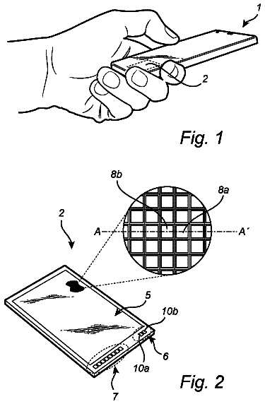
FIG. 1 and FIG. 2 illustrate a top view and an enlarged top perspective view of a fingerprint sensor according to an embodiment of the present invention, respectively.
FIG. 3A to FIG. 3C illustrates a cross-section view of the fingerprint sensor in FIG. 2 , respectively.
FIG. 4 illustrates a top view of a second ESD protection electrode according to an embodiment of the present invention.
FIG. 5 illustrates a top view of another second ESD protection electrode according to an embodiment of the present invention.
FIG. 6 illustrates a top view of another second ESD protection electrode according to an embodiment of the present invention.
FIG. 7 is a functional block diagram of an ESD protection circuit according to an embodiment of the present invention.
FIG. 8 illustrates a cross-section view of a fingerprint sensor according to an embodiment of the present invention.
FIG. 9 illustrates a top view of a first ESD protection electrode according to an embodiment of the present invention.
Detailed description
FIG. 1 and FIG. 2 illustrate a top view and an enlarged top perspective view of a fingerprint sensor 1 having electrostatic discharge (ESD) protection according to an embodiment of the present invention. As shown in FIG. 1 , the fingerprint sensor 1 includes a fingerprint sensor electrode array 10 , an ESD protection electrode E 1 , an ESD protection circuit ESD_PC connected to the ESD protection electrode E 1 . The fingerprint sensor electrode array 10 includes multiple sensor electrodes 11 arranged in a matrix, wherein a grid area is formed between the multiple sensor electrodes 11 . The ESD protection electrode E 1 is coplanar with the fingerprint sensor electrode array 10 on a plane (e.g., X-Y plane), wherein the ESD protection electrode E 1 is formed in the grid area and presents a grid pattern.
In one embodiment, the fingerprint sensor electrode array 10 further includes multiple dummy electrodes 12 , formed outside of the multiple sensor electrodes 11 , and connected to the ESD protection electrode E 1 , wherein each of the multiple dummy electrodes 12 is formed in an area surrounded by the grid pattern. The ESD protection circuit ESD_PC is connected to the ESD protection electrodes E 1 , for providing an ESD path. In one embodiment, the ESD protection circuit ESD_PC may be a ground or a low electric potential terminal.
As shown in FIG. 2 , the fingerprint sensor 1 further includes an ESD protection electrode E 2 (denoted with slash patterns) formed below the grid area formed by the multiple sensor electrodes 11 , and the ESD protection electrode E 2 is not overlapped with the multiple sensor electrodes 11 along a Z direction. In one embodiment, a projection of the ESD protection electrode E 2 onto the X-Y plane is overlapped with the ESD protection electrode E 1 , wherein a portion of the ESD protection electrodes E 1 that is overlapped with electrodes E 2 is denoted with slash patterns, and another portion of the ESD protection electrode E 1 that is not overlapped with electrodes E 2 is denoted with dot patterns. In the embodiment of FIG. 2 , the ESD protection electrode E 2 is configured with multiple cross-shape patterns. The ESD protection electrodes E 1 may connect to the ESD protection electrode E 2 by multiple conductive via V 1 . When the fingerprint sensor 1 encounters the electrostatic current, the electrostatic current may flow to the ESD protection circuit ESD_PC by the ESD protection electrode E 1 , to protect the fingerprint sensor 1 from damaging, so as to achieve the purpose of ESD protection.
FIG. 3A to FIG. 3C illustrates a cross section A-A′, a cross section B-B′ and a cross section C-C′ in FIG. 2 , respectively. The cross section A-A′ is located at where the ESD protection electrodes E 1 and E 2 and the conductive via V 1 are overlapped, and is not overlapped with the sensor electrode 11 . The cross section B-B′ is located at where the ESD protection electrodes E 1 and E 2 and the conductive via V 1 are not overlapped, and the sensor electrode 11 is sectioned by the cross section B-B′. The cross section C-C′ is located at where the ESD protection electrodes E 1 and E 2 and the conductive via V 1 are overlapped, and the sensor electrode 11 is sectioned by the cross section C-C′.
In FIG. 3A to FIG. 3C , the fingerprint sensor 1 further includes a protection layer PAV, a dielectric layer DI 1 , and a substrate SUB, wherein the substrate SUB is used for forming ESD protection circuit ESD_PC and a sensor circuit (not shown) for detecting the sensor electrode 11 , and the substrate SUB may include conductive layers and dielectric layers. The protection layer PAV covers the fingerprint sensor electrode array 10 and the ESD protection electrode E 1 . A top surface of the protection layer PAV (i.e., another surface in opposite to the surface of the protection layer PAV covering the fingerprint sensor electrode array 10 ) provides a contact surface for the finger of the user. The dielectric layer DI 1 is formed between the ESD protection electrodes E 1 and E 2 , and covers the ESD protection electrode E 2 . The dielectric layer DI 1 includes the multiple conductive via V 1 for connecting the ESD protection electrodes E 1 and E 2 .
As shown in figures, the ESD protection electrode E 1 and the fingerprint sensor electrode array 10 are formed in a same layer, e.g. a layer that is closest to the protection layer PAV. In one embodiment, the ESD protection electrode E 1 is coplanar with the fingerprint sensor electrode array 10 . When detecting the fingerprint of the user, there is only the protection layer PAV between the fingerprint sensor electrode array 10 and the finger, which is benefit for obtaining greater induced capacitance variation. The multi-layer structure of the ESD protection electrodes E 1 and E 2 , compared with the single ESD protection electrode E 1 , can provide an ESD path with lower impedance, such that the electrostatic current tends to flow to the ESD protection electrode E 1 , which enhances ESD protection effect. Any fingerprint sensor meets the above mentioned structure and corresponding function and purpose shall be incorporated in the present invention, those skilled in the art can make modifications or alterations accordingly, which is not limited to the embodiments of the present invention.
FIG. 9 illustrates a top view of an ESD protection electrode E 1 according to an embodiment of the present invention, where the ESD protection electrode E 1 presents a grid pattern. In addition, there is no specific limitation to the pattern presented by the ESD protection electrode E 2 . In one embodiment, the pattern presented by the ESD protection electrode E 2 may be the grid pattern presented by the ESD protection electrode E 1 in FIG. 9 .
FIG. 4 illustrates a top view of an ESD protection electrode E 2 according to an embodiment of the present invention, wherein the ESD protection electrode E 2 comprises multiple cross-shape patterns 40 and multiple rectangular patterns 41 . FIG. 5 illustrates a top view of another ESD protection electrode E 2 , wherein the ESD protection electrode E 2 comprises multiple rectangular patterns 50 arranged in multiple columns or multiple rows; in other words, the rectangular pattern 50 may be arranged in multiple columns or multiple rows along the X direction or the Y direction. FIG. 6 illustrates a top view of another ESD protection electrode E 2 , wherein the ESD protection electrode E 2 comprises multiple cross-shape patterns 60 .
In FIG. 4 to FIG. 6 , the blocks denoted with dash line represent areas which are overlapped with the sensor electrode 11 along the Z direction, that is, the configuration of the ESD protection electrode E 2 is not overlapped with the sensor electrode 11 along the Z direction. As shown in figures, the cross-shape pattern is located between four adjacent blocks denoted with dash line. In the ESD protection electrodes E 2 of FIG. 4 to FIG. 6 , each portion (e.g., the cross-shape pattern, or the rectangular pattern) is connected to the ESD protection electrode E 1 in the upper layer by one or more conductive via V 1 .
FIG. 7 illustrates a functional block diagram of the ESD protection circuit ESD_PC according to an embodiment of the present invention. The ESD protection circuit ESD_PC includes a connecting terminal 70 and discharge units 71 and 72 . The connecting terminal 70 is connected to the ESD protection electrode E 1 . The discharge unit 71 is coupled between a high electric potential terminal VDD and the connecting terminal 70 , for providing a discharge path for positive static electric charges to the high electric potential terminal VDD. The discharge unit 72 is coupled between a low electric potential terminal VSS and the connecting terminal 70 , for providing a discharge path for negative static electric charges to the low electric potential terminal VSS, wherein the low electric potential terminal VSS may be a ground.
In one embodiment, the discharge units 71 and 72 may be a diode. A cathode of the discharge unit 71 is coupled to the high electric potential terminal VDD, and an anode of the discharge unit 71 is coupled to the connecting terminal 70 . An anode of the discharge unit 72 is coupled to the low electric potential terminal VSS, and a cathode of the discharge unit 72 is coupled to the connecting terminal 70 .
In another embodiment, the discharge unit 71 is a P-type Metal-Oxide-Semiconductor (PMOS) transistor, wherein a drain of the PMOS transistor is connected to the connecting terminal 70 , a gate of the PMOS transistor is connected to a source of the PMOS transistor, and the source is connected to the high electric potential terminal VDD. The discharge unit 72 is a N-type Metal-Oxide-Semiconductor, (NMOS) transistor, wherein a drain of the NMOS transistor is connected to the connecting terminal 70 , a gate of the NMOS transistor is connected to a source of the NMOS transistor, and the source of the NMOS transistor is connected to the low electric potential terminal VSS. In another embodiment, the first and second discharge units 71 and 72 are Silicon Controlled Rectifier (SCR).
In the embodiment of FIG. 7 , the fingerprint sensor 1 further includes a driver circuit 73 and a sensor circuit 74 . The sensor circuit 74 is connected to the sensor electrode 11 , for sensing a capacitance variation of the sensor electrode 11 , to recognize the ridge or valley of the fingerprint. The driver circuit 73 is coupled to the ESD protection electrode E 1 , and cooperates with the sensor circuit 74 to provide different voltages to the ESD protection electrode E 1 at different timing phases, in order to decrease influence to the sensing results of the fingerprint due to parasitic capacitances between the sensor electrode 11 and the ESD protection electrodes E 1 and E 2 . The more layers of the connected ESD protection electrodes, the lower total impedance of the connected ESD protection electrodes can provide. The present invention is not limited to only two layers of the ESD protection electrodes. For example, in the embodiment of FIG. 8 , in addition to the ESD protection electrode E 1 and E 2 in FIG. 3 , the fingerprint sensor 8 further includes an ESD protection electrode E 3 formed below the grid area formed by the multiple sensor electrodes 11 , and the ESD protection electrode E 3 is not overlapped with the sensor electrode 11 along the Z direction. A dielectric layer DI 2 is formed between the ESD protection electrodes E 2 and E 3 , and covers the ESD protection electrode E 3 . The dielectric layer DI 2 includes multiple conductive via V 2 , where the conductive via V 2 is used for connecting the ESD protection electrodes E 3 and E 2 .
According to the configurations of the present invention, each of the sensor electrodes 11 may have a same size, which is not influenced by the ESD protection electrode E 1 or E 2 . The ESD protection electrode E 2 (or both the ESD protection electrodes E 2 and E 3 ) in lower layer can provide electrostatic current blocking effect, to prevent electrostatic power from flowing downwardly to the inner circuit and element of the fingerprint sensor 1 .
Those skilled in the art will readily observe that numerous modifications and alterations of the device and method may be made while retaining the teachings of the invention. Accordingly, the above disclosure should be construed as limited only by the metes and bounds of the appended claims.
 Lapsed, fee not paid7 drawings