Lapsed, fee not paid2 drawings
Robotics & Automation · US 9,981,384 B2
Mechanical arm and pickup device
The present invention provides a mechanical arm and a pickup device.
US 9,983,553 B2 · Assignee: Hitachi, Ltd. · Inventors: Nishi; Masataka
Sheet 1 of 25 from the published document. All sheets in the USPTO PDF
An object of the present invention is to provide an autonomous system that realizes expected operation in a form in which the soundness of the operation can be proved to a third party in adaptation to an external factor that dynamically varies and to enhance a working ratio in autonomous operation. The autonomous system is provided with a function for dynamically leading a satisfiable combination of a requirement for the soundness of operation and expected operation on the basis of the information of operating environment acquired via exterior world measurement means, a function for generating control logic for realizing the expected operation, a function for recording the control logic, the requirement for sound operation and the expected operation, and a function for presenting the record in a form in which the third party can read the record.
A system equipped with measurement means of a situation of operating environment and provided with an autonomous function for judging and controlling autonomous operation without requiring the intervention of an operator according to a stored program has been researched. One example of a concrete autonomous system is an autonomous mobile robot that is disclosed in Patent Literature 1 and that travels to a destination, satisfying a condition of sound operation for avoiding collision with a circumferential person who indeterminately moves, an autonomous work system that executes predetermined work in addition to the corresponding mobile function, and a fully autonomous running type automobile utilizing a function for generating a path to a remote destination. In Patent Literature 2, a robot provided with an autonomous mobile function in closed environment is presented. In Patent Literature
8 of 25 drawing sheets so far from the published document, cropped to the drawing. Every sheet is in the USPTO PDF.
What the patent claimed, word for word. All of it is now free to use.
The present invention relates to an autonomous operation control unit that determines an autonomous system operated in open environment and the operation of the autonomous system.
A system equipped with measurement means of a situation of operating environment and provided with an autonomous function for judging and controlling autonomous operation without requiring the intervention of an operator according to a stored program has been researched.
One example of a concrete autonomous system is an autonomous mobile robot that is disclosed in Patent Literature 1 and that travels to a destination, satisfying a condition of sound operation for avoiding collision with a circumferential person who indeterminately moves, an autonomous work system that executes predetermined work in addition to the corresponding mobile function, and a fully autonomous running type automobile utilizing a function for generating a path to a remote destination.
In Patent Literature 2, a robot provided with an autonomous mobile function in closed environment is presented.
In Patent Literature 3, an autonomous work system remotely operated via a channel is disclosed. This patent literature discloses an embodiment that a remote operation function at real time and an autonomous operation function can be selected, a remote operator programs expected operation beforehand or instructs it at a small frequency as required and the autonomous work system implements the instructed expected operation.
Patent Literature 4 discloses, as a semi-autonomous system in which an operator rides and ordinarily directly directs expected operation, an autonomous system provided with a function for detecting distance between cars and making intervention control so as to avoid collision between adjacent running vehicles and specialized in running support. CITATION LIST Patent Literature
Patent Literature 1: Japanese Unexamined Patent Application Publication No. 2009-157735
Patent Literature 2: Japanese Unexamined Patent Application Publication No. 2009-80804
Patent Literature 3: Japanese Unexamined Patent Application Publication No. 2012-51560
Patent Literature 4: Japanese Unexamined Patent Application Publication No. 2012-30665 SUMMARY OF INVENTION Technical Problem
An autonomous system operated in open environment is required to determine operation in adaptation to an external factor that dynamically and indeterminately varies. However, in the existing method of supposing a concrete operation mode at a design stage and all designing individual control logic, it is not guaranteed to be able to realize expected operation, satisfying the soundness of operation according to varying external environment and it is difficult to all verify realizability in a short time.
Besides, in spite of a characteristic that the autonomous system is operated without intervention by a person, an external burden of proof to soundness in an operation determination process in which its behavior is determined and transparency for backing up this, that is, observability in the operation determination process is not considered, an operation mode and the corresponding control logic are stored in the form of a program and others, it is difficult that a third party directly refers to them and evaluates them in operation, and information actually acquired by observation is limited to behavior finally realized according to the control logic.
The method presented in Patent Literature 1 proposes a method of supposing a situation in which a mobile obstacle called a pedestrian exists in circumferential environment of the autonomous system, dynamically setting a non-enterable region, autonomously adjusting the non-enterable region by extending or reducing the non-enterable region, and installing control logic including an operation mode for pursuing expected operation in which a path for avoiding the non-enterable region is generated and followed in designing.
However, operation when a region including the current position of the autonomous system suddenly belongs to the inside of the non-enterable region according to the variation of an external factor is not supposed, and when operation is continued according to a program set beforehand in such a case, soundness is not guaranteed because operation in such a situation is not verified.
Therefore, it is natural that operation be described so that the autonomous system is stopped from a viewpoint of safety in the circumference of the autonomous system as one measure for abnormality in designing the control logic. However, in such operational environment that the autonomous system cannot be suddenly stopped, the soundness of the operation is lost since the stop.
Moreover, when solution is made by means such as a reset by a person in abnormal termination, operation is stopped every time there occur operation modes in which the soundness of operation is not verified, and a rate of operation in autonomous operation may be remarkably deteriorated in spite of a characteristic that the autonomous system is operated without intervention by a person.
Therefore, it is important to improve the comprehensiveness of an operation mode in which the soundness of operation is verified.
In the method presented in Patent Literature 1, an operation mode in which the soundness of operation is not verified is equivalent to operation in a state in which control logic designed corresponding to an operation mode supposed at the stage of design does not satisfy a premise tacitly assumed so as to satisfy the soundness of operation. Since such an operational situation is not supposed at the time of design, it is sequentially modified when the operational situation is found in a prototype test. However, in such a method of sequentially modifying on the basis of the operation mode initially supposed and designing the control logic of the autonomous system, it is difficult to guarantee the comprehensiveness of operating environment actually encountered and the soundness of the corresponding control logic. In addition, the method presented in Patent Literature 1 has a problem that the number of operation modes to be supposed and the number of control logics to be designed increase explosively in combination according to the variety of external factors accompanied by the setting and a change of a non-enterable region. Solution to Problem
To solve the problems, an autonomous control device that generates operation control logic for implementing operation adapted to an internal state of a self-system and an external factor acquired by exterior world measurement means in open exterior environment on the basis of the operation control logic stored in a storage and instructs a drive device to operate in the open exterior environment is provided with an autonomous operation control unit that generates operation control logic and control logic on the basis of a constraint corresponding to an external factor acquired from the exterior world measurement means and an internal state of the autonomous system and a constraint related to expected operation demanded for the autonomous system and the soundness of the operation every time the operation control logic is sequentially reconstructed, writes the generated operation control logic and information acquired from the exterior world measurement means to the recording unit, and instructs the autonomous system to operate on the basis of the control logic, and an expected operation determination unit that designates the expected operation demanded for the autonomous system on the basis of a result of the judgment of the expected operation and the soundness of the operation by the autonomous operation control unit. Advantageous Effects of Invention
Since sound operation is implemented in an operation mode adapted to a varying external factor by sequentially generating control logic in which the soundness of the operation is verified and the generated control logic is recorded and presented, a third party can verify the soundness of the operation by referring to an operation determination process.
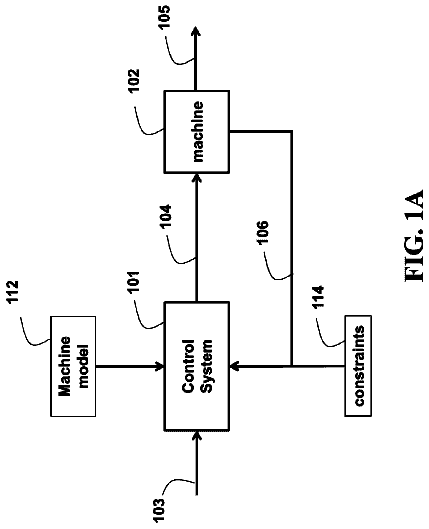
FIG. 1 is a block diagram showing an autonomous system.
FIG. 2 shows a process flow of an autonomous operation control unit.
FIG. 3 shows the definition of a closed region.
FIG. 4 shows the notation of a constraint and a logical expression.
FIG. 5 shows the definition of control logic L.
FIG. 6 shows the representation of operation in a restriction form.
FIG. 7 shows the representation of an operating rule in a restriction form with a relaxed condition and expected operation.
FIG. 8 shows a flow of a construction process of data structure showing connection relation between partial regions.
FIG. 9 shows the classification of connection relation between two closed regions and a determination method.
FIG. 10 shows an example of division into partial closed regions.
FIG. 11 is a functional block diagram showing restriction form conversion means A.
FIG. 12 shows a conversion rule which the restriction form conversion means A uses.
FIG. 13 shows a flow of a process by the restriction form conversion means A.
FIG. 14 is a functional block diagram showing restriction form conversion means B.
FIG. 15 shows an example of the description of a program that designates expected operation.
FIG. 16 shows control structure of a program that designates expected operation determination logic.
FIG. 17 shows a process flow by the restriction form conversion means B.
FIG. 18 shows a process flow according to the expected operation determination logic.
FIG. 19 shows the generation of operation control logic T and control logic L.
FIG. 20 shows the analysis of connection relation between closed regions.
FIG. 21 shows a list of executable operation control logics.
FIG. 22 shows moving operation between two closed regions which the operation control logic shown in FIG. 21 designates.
FIG. 23 shows a flow of an execution process of the control logic.
FIG. 24 shows a flow of the execution process of the control logic.
FIG. 25 shows a flow of the execution process of the control logic.
FIG. 26 shows information stored in a recording unit and a method of utilizing a presentation device.
FIG. 27 shows the control of the autonomous system by a remote operator.
FIG. 28 is an internal block diagram showing an autonomous running system.
FIG. 29 shows the autonomous running system that enters an intersection.
FIG. 30 shows contents of an autonomous running control program used in a third embodiment.
FIG. 31 shows a conversion rule used by restriction form conversion means A in the third embodiment.
FIG. 32 shows a restriction form K with a relaxing condition output by the restriction form conversion means A in the third embodiment.
FIG. 33 shows operation control logic generated when a signal value is not “red” in the third embodiment. DESCRIPTION OF EMBODIMENTS First Embodiment
A first embodiment of an autonomous system using the present invention will be described below. FIG. 1 is a block diagram showing the autonomous system. The autonomous system 01 operated in open exterior environment is provided with an autonomous control device 010 , exterior world measurement means 011 , internal state measurement means 012 , a presentation device 013 and a drive device 014 . The autonomous control device 010 is configured by an autonomous operation control unit 0101 , a recording unit 0102 , expected operation determination logic 0103 , restriction form conversion means A ( 0104 ) and restriction form conversion means B ( 0105 ).
The restriction form conversion means A ( 0104 ) converts information of open exterior environment information acquired via the exterior world measurement means 011 to a restriction form and passes it to the autonomous operation control unit 0101 .
The recording unit 0102 stores a generation record 01021 of operation control logic generated by the autonomous operation control unit 0101 . The autonomous operation control unit 0101 presents the generation record 01021 of this operation control logic to the presentation device 013 as required.
The expected operation determination logic 0103 is operated according to an expected operation designation program 01031 , the restriction form conversion means B 0105 converts this expected operation determination logic 0103 to a restriction form, and the restriction form conversion means B 0105 passes it to the autonomous operation control unit 0101 . The autonomous operation control unit 0101 determines the satisfiability of expected operation converted to the restriction form and returns its result as satisfiable, unsatisfiable or completed. The autonomous operation control unit 0101 outputs a control command to the drive device 014 after a process shown in FIG. 2 .
FIG. 2 snows a process flow executed in the autonomous control device 010 .
First, in a step 021 , lists of restriction forms output by the restriction form conversion means A ( 0104 ) and the restriction form conversion means B ( 0105 ) are received and the restriction forms to be processed are set. In the next step 022 , the lists of restriction forms received in the step 021 are stored in the recording unit 0102 .
In a step 023 , operation control logic T of the whole autonomous system 01 that satisfies a list of restriction forms set in the step 021 and control logic L for calculating a control command output to the drive device 014 are generated. In a step 024 , it is verified that the operation control logic T which satisfies all the restriction forms set in the step 021 and the control logic L are realizable. When a result of the verification is determined as realizable, the process proceeds to a step 026 and in the step 026 , the operation control logic T and the control logic L are stored in the recording unit 0102 . In the meantime, when the result of the verification is determined as unrealizable, the process proceeds to a step 025 , the list of restriction forms recorded in the step 022 is read, and at least a part of the restriction forms set in the step 021 is relaxed. For example, when the restrictions determined as unsatisfiable in the step 024 can be relaxed, they are replaced with the relaxed restriction forms. Next, the processing is returned to the step 021 and the processing is repeated.
After the operation control logic T and the control logic L are recorded in the step 026 , the process proceeds to a step 027 and a control command is output to the drive device 014 on the basis of the control logic L. In a step 028 , it is verified whether the restriction form set in the step 021 is updated or not. When the restriction form is not updated, the processing is returned to the step S 27 , operation is continued on the basis of the same control logic L, and when the restriction form is updated, the processing is returned to the step 021 .
Next, a detailed method of realizing data structure used inside the autonomous operation control unit 0101 will be described. A constraint will be defined as a function COND(X) that returns a truth value TRUE
or FALSE
for a set internal state X below. FIG. 3 shows the definition of constraints that represent a closed region REGION(Y) by combining the plural constraints (COND_0(Y) to COND_3(Y)). These constraints are constructed as a logical product of the individual constraint for determining the inside of a half-plane group that provides planes of the closed region in parameter space Y representing the internal state. In addition, a more complex constraint can be represented by combining the logical product AND, the logical product sum OR, negation NOT and conditional restriction of the individual constraint. FIG. 4 shows operators and their symbol notations for constructing a complex constraint by combining constraints.
Referring to FIG. 5 , a method of representing operation which the control logic L outputs will be described using a constraint showing a closed region and a conditional constraint below. In this example, operation that moves from a point P 0 in a closed region R 0 & (!R 1 ) to a point P 2 in a closed region !R 0 &R 1 via a point P 1 in a closed region R 0 &R 1 in the defined two closed regions R 0 , R 1 is represented as Action.
FIG. 6 shows the definition of a restriction form (an operator) having a constraint Ci as an argument.
An operator X[C 0 ] for a constraint C 0 is a restriction form for representing conditional operation. The operator denotes a restriction form for representing the operation that satisfies the constraint C 0 to be an argument (the operation in which an evaluation value of the constraint C 0 is TRUE) in the next order in a suitably set sequential string.
An operator [C 0 ]U[C 1 ] for constraints C 0 and C 1 is a restriction form for representing conditional operation. Until the constraint C 1 becomes 1, the operator represents the operation that continues to at least maintain 1 as a value of the constraint C 0 .
An operator [C 0 ]R[C 1 ] for the constraints C 0 and C 1 is a restriction form for representing conditional operation. Until the constraint C 0 becomes 1 at the first time since the current time, the constraint C 0 continues to be 1.
An operator G[C 0 ] for the constraint C 0 is a restriction form for representing conditional operation. The operator represents the operation that continues to maintain 1 as the value of the constraint C 0 at arbitrary time.
An operator F[C 0 ] for the constraint C 0 is a restriction form for representing conditional operation. The operator represents the operation that meets “the constraint C 0 =1” at some time in future since the current time more than once.
An operator [C 0 ]W[C 1 ] for the constraints C 0 and C 1 is a restriction form for representing conditional operation. The operator represents the operation that continuously continues to maintain 1 as the value of the constraint C 0 or the operation that continues to maintain 1 as the value of the constraint C 0 at least until the constraint C 1 becomes 1 since the current time.
FIG. 7 snows the definition of a restriction form with a relaxing condition having a restriction form Ci as an argument and expected operation. Each restriction form with a relaxing condition is given in the form of the logical OR of one or more restriction forms and is classified on the basis of the possibility of relaxation of restriction related to a sequential string. For each restriction form with a relaxing condition, presented contents to the presentation device 013 that corresponds to a case in which the relaxing condition is applied are determined.
The autonomous operation control unit 0101 receives data of the restriction forms represented in these operators and transcription from the restriction form conversion means A ( 0104 ) and the restriction form conversion means B ( 0105 ).
FIGS. 8 and 9 show data structure that represents connection relation between partial closed regions by binarizing internal state space using a group of constraints equivalent to a closed region defined in the internal state space and its processing method. In this case, the internal state space is binarized by setting the inside including an outer edge of the closed region to 1 and setting the outside to 0. A case that a single closed region Y is newly added in S 902 in a situation in which a group of closed regions X is already defined in S 901 according to a process flow shown in FIG. 8 is classified into any of a case 1 that two closed regions accord, a case 2 that two closed regions are partially overlapped and are touched, a case 3 that two closed regions are separated, a case 4 that two closed regions are in the relation of inclusion, a case 5 that two closed regions are in the relation of covering, and a case 6 that one closed region divides the other closed region, on the basis of connection relation between the group of closed regions X and the group and the closed region Y as shown in FIG. 9 .
In S 903 , the validity of classification into the case 1 for example is determined when solution that meets the constraint [C 0 &C 1 ] using the constraint C 0 that represents the closed region X and the constraint C 0 that represents the closed region Y exists (represented as SAT), no solution that meets the constraint [C 0 &!C 1 ] exists (represented as UNSAT), no solution that meets the constraint [!C 0 &C 1 ] exists and solution that meets the constraint [!C 0 &!C 1 ] exists. As for the other five cases, the criterion of satisfying solution shown in FIG. 9 has only to be similarly applied to the combination of each constraint.
The connection relation of the partial closed regions divided by mutual closed regions is updated in S 904 on the basis of the connection relation of the closed regions determined as described above and the region is added on the basis of a result of the update in S 905 .
FIG. 10 shows an example in which the constraint C 1 showing the closed region R 1 and a constraint C 2 showing a closed region R 2 are sequentially added to the constraint C 0 showing the closed region R 0 in the process shown in FIG. 8 .
The closed region R 0 is defined as a region that meets that the constraint C 0 is 1 and the constraint C 0 is defined as the logical product of the smallest constraints C 0 - 0 , C 0 - 1 , C 0 - 2 , C 0 - 3 . As the constraint C 0 divides the closed region R 0 into the inside of the closed region (closed region ID=R 0 ) and the outside (closed region ID=EXTERIOR), these divided regions are added in S 905 .
Therefore, when the closed region R 1 defined as a region that meets that the constraint C 1 is 1 is added in S 902 , R 1 is newly set as closed region ID. Next, it is determined in S 903 that the closed regions R 0 and R 1 are classified into the case 2 shown in FIG. 9 , the closed region R 0 is divided into R 0 - 0 and R 0 - 1 in S 904 , and the closed region R 1 is divided into R 1 - 0 and R 1 - 1 . Since R 0 - 0 and R 0 - 1 , and R 1 - 0 and R 1 - 1 are in succession in the first place, these connection is added, connection relation is updated, and since R 0 - 1 and R 1 - 1 are equivalent to the case 1 (two closed regions accord), connection relation from R 0 - 1 to R 1 - 0 and from R 1 - 1 to R 0 - 1 is added, and connection relation is updated. Further, when the closed region R 2 is added, similar processing is also performed.
FIG. 11 is a functional block diagram showing the restriction form conversion means A ( 0104 ). The restriction form conversion means A ( 0104 ) is provided with the classification of recognition objects, a list of constraints provided in relation to each object and state values of the recognition objects, and a template of a restriction form with a relaxing condition that indicates an operating rule corresponding to the recognition object respectively shown in FIG. 12 as a conversion rule beforehand. A restriction form with a relaxing condition is generated for each recognition object using the conversion rule according to a process flow shown in FIG. 13 and a logical product K ( 01045 ) is output to the autonomous operation control unit 0101 together with a list of the restriction forms.
Concretely, an exterior world recognition unit 01041 receives information M ( 0111 ) of a recognition object which the exterior world measurement means 011 acquires and classifies the information for each recognition object according to the template of the conversion rule (S 1701 ). The exterior world recognition unit sets a list of constraints for each classification of the recognition object (S 1702 ), acquires and sets a state value for each classification of the recognition object (S 1703 ), and a constraint generation unit 01042 sets a restriction form with a relaxing condition that directs an operating rule specified by the template for each recognition object (S 1704 ). The constraint generation unit generates the logical product K of the set restriction forms with the relaxing condition and outputs it to the autonomous operation control unit 0101 (S 1705 ).
In addition, the state value of the recognition object set via the exterior world recognition unit 01041 is output to the autonomous operation control unit 0101 as an observation point of a current state together with a state value of the inside of the autonomous system 01 which is acquired via the internal state measurement means 012 .
The exterior world measurement means 011 is means for acquiring information required when the autonomous system 01 acts in open external environment and is not limited to a passive device represented by an image sensor and a measurement sensor. For one example, the exterior world measurement means may also be a device that receives data input from a system in open external environment to the exterior world recognition unit 01041 via any channel.
Referring to FIGS. 14 to 18 , a process in which the expected operation determination logic 0103 outputs a restriction form with a relaxing condition E to the autonomous operation control unit 0101 via the restriction form conversion means B ( 0105 ) and resets an output value on the basis of its response (SAT: satisfiable, UNSAT: unsatisfiable, COMP: completed) will be described below.
As shown in FIG. 14 , the expected operation determination logic 0103 is provided with the expected operation designation program 01031 for generating expected operation shown in an example in FIG. 15 inside and designates the restriction form conversion means B as a list of restriction forms with a relaxing condition according to operation control logic shown in FIG. 16 . The expected operation determination logic 0103 continues to operate until an operation termination condition is met from the start of operation according to a process flow shown in FIG. 17 , referring to operation ID shown in FIG. 16 .
As shown in FIG. 16 , the smallest unit of the program that designates expected operation is defined for each individual operation ID, and is operated on the basis of control logic configured by operation 010311 described in a restriction form with a relaxing condition, an operation completion determination condition 010312 described as a constraint and operation ID ( 010313 , 010314 , 010315 in order) of a transition destination designated for every three types of responses (SAT, UNSAT, COMP) returned from the autonomous operation control unit 0101 to the expected operation determination logic 0103 as a result of determining the satisfiability of the operation equivalent to the step 024 shown in FIG. 2 . In this case, an initial value of the operation ID is described as IDS and a final state is described as IDE.
FIG. 17 shows the process flow in the restriction form conversion means B ( 0105 ). The restriction form conversion means B refers to operation ID designated by the expected operation determination logic 0103 (S 2201 ) and acquires the expected operation E ( 010311 ) in a restriction form with a relaxing condition corresponding to the operation ID, the operation completion determination condition 010312 and the operation ID ( 010314 ) of the transition destination after the completion of the operation from a branching condition after the acquisition of the response (S 2202 , S 2203 , S 2204 ). The restriction form conversion means B acquires the operation 010311 of the restriction form with the relaxing condition corresponding to the acquired operation ID of the transition destination after the completion of the operation (S 2205 ), and outputs the restriction form with the relaxing condition E that designates expected operation, a list of constraints that configure restriction form E and the operation completion condition 010312 to the autonomous operation control unit 0101 (S 2206 , S 2207 , S 2208 ).
FIG. 18 shows a response process to the autonomous operation control unit 0101 using the designated operation ID. In a step S 2301 , the operation ID is set to an initial value IDS, the process flow shown in FIG. 17 of the restriction form conversion means B is executed (S 2302 ), and a response from the autonomous operation control unit is awaited (S 2303 ). When a response value is SAT (satisfiable), control is returned to S 2303 after processing when the response value is “satisfiable” is executed, and a response is successively awaited. When a response value is COMP (completed), a step S 2306 is executed. Conversely, when a response value is UNSAT (unsatisfiable), a step S 2305 when the response value is “unsatisfiable” is executed. Until operation ID of a transition destination updated in S 2306 finally reaches IDE (a final state) as the operation ID by determination processing in S 2307 , the expected operation determination logic 0103 is continuously operated.
FIG. 19 shows a flow of a generation process by the operation control logic T and the control logic L. This is equivalent to the processing in the step 023 shown in FIG. 2 .
First, initial processing for analyzing a partial closed region divided by overlap of closed regions and connection relation between the closed regions is executed according to a process flow shown in FIG. 20 . First, the restriction form with the relaxing condition K and the list of constraints to be an argument respectively passed to the autonomous operation control unit 0101 as shown in FIG. 11 , the restriction form with the relaxing condition E and the list of constraints to be an argument respectively passed to the autonomous operation control unit 0101 as shown in FIG. 14 are acquired.
Correspondence between the partial closed region and the constraint and connection relation between the partial closed regions are generated on the basis of both the lists of constraints according to the process flow shown in FIG. 8 (a step 02301 ) and a logical state value is generated. In addition, an operating rule A which is a restriction form with a relaxing condition is newly set as a logical product of the restriction forms with the relaxing condition K, E (a step 02305 ).
Next, a state value of the recognition object shown in FIG. 11 and a group of internal states of the autonomous system 01 acquired from the internal state measurement means 012 are put together and observation information Y (t=0) of a current state is set. A truth value of an individual constraint is evaluated using the observation information Y of the current state and an initial value RINIT of closed region ID to which a binarized state of the autonomous system 01 belongs is specified (a step 02302 ).
FIG. 21 shows a list of things which can be realized by the operation control logic T generated in the step 023 . Initially, the list is a null set and the RINIT is added to a list of operation control logic ID. Unless a list of the operation control logic shown in FIG. 21 is a null set, the following processing is continued.
Referring to the flow shown in FIG. 19 again, it is determined whether all operation control logics T_i registered in a list of the operation control logic T shown in FIG. 21 meet the operation completion determination condition ( 010312 ) shown in FIG. 21 (a step 02304 ). When they meet the operation completion determination condition, a generation process of the operation control logic T is finished and in a step 02390 , one operation control logic is selected, taking precedence over the operation control logic to which no [relaxing condition afforded to expected operation] is applied. For one example, the operation control logic having a smaller value of operation execution order ID required until operation is completed may also be selected.
The individual operation control logic T_i is designated as a chain of closed region ID to be varied for each operation execution order ID, and truth values of one or more constraints are necessarily inverted in transition between closed regions according to the definition of the closed region shown in FIG. 3 . The control logic L corresponding to each transition between closed regions is defined as a constraint in a step 02391 utilizing this characteristic according to a procedure shown in FIG. 19 .
Next, the autonomous operation control unit 0101 returns a response of SAT (satisfiable) to the expected operation control logic 0103 (a step 02307 ) and terminates the operation.
Conversely, when operation control logic that does not meet the operation completion determination condition ( 010312 ) remains in the list shown in FIG. 21 (a step 02304 : No), processing for generating the operation control logic T is continued.
Then, one operation control logic that does not meet the operation completion determination condition ( 010312 ) is selected from the list shown in FIG. 21 and shall be called TTMP. As for TTMP, after closed region ID corresponding to maximum operation execution order ID shown in FIG. 21 is acquired, a truth value of each constraint that configures the closed region is evaluated and is binarized, it is evaluated on the basis of respective closed region ID whether there is a transition destination closed region which has connection relation and meets the operating rule A set in the step 02305 .
When there is none, the operation control logic TTMP is deleted and the process proceeds to a step 02303 . In the step 02303 , when the list of the operation control logic T shown in FIG. 21 is a null set, the autonomous operation control unit 0101 returns a response of UNSAT (unsatisfiable) to the expected operation control logic 0103 (a step 02308 ) and terminates the operation.
Conversely, when one or more transition destination closed regions exist, the process proceeds to a step 02306 and update to operation control logic in which the transition destination closed region is added to the operation control logic TTMP is made. In addition, when transition to the transition destination closed region is realized by applying any relaxing condition in the operating rule A set in the step 02305 , the relaxing condition V is recorded in the corresponding location corresponding to the operation control logic TTMP shown in FIG. 21 .
The abovementioned process is continued until the process finally reaches the step 02307 or 02308 and is finished. At the time of the finish, the autonomous operation control unit 0101 terminates the step 023 .
FIG. 22 shows a problem that operation that moves from a state in which the closed region ID shown in FIG. 10 is R 0 - 0 to a closed region having the closed region ID of R 2 - 2 in a range where the region ID is not EXTERIOR is generated. In this case, according to the process flow shown in FIG. 19 , the operation from R 0 - 0 finally toward R 2 - 2 via R 0 - 1 , R 1 - 0 , R 1 - 1 , R 1 - 2 and R 2 - 1 is generated, and finally, the operation control logic shown in FIG. 21 is acquired.
When the process reaches the step 02307 shown in FIG. 19 , it is regarded in the step 024 that the verification succeeds and the process proceeds to the step 026 . In the step 026 , the list T ( 02392 ) of the operation control logic generated according to the process flow shown in FIG. 19 and control logic L_i correlated with individual operation control logic T_i are all stored in the recording unit 0102 . The process proceeds to the step 027 , the control logic L is executed, and a control command is output to the drive device 014 .
A process flow for converting the operation control logic T and the control logic L respectively generated in FIG. 19 to a control command will be described using FIGS. 23 to 25 below.
In a step 02309 , a dynamic model of the autonomous system 01 which is a control object is acquired. The dynamic model may also be acquired by identifying the system beforehand or may also be generated during operation.
In a step 02310 , the control logic L generated in the step 02391 is acquired.
In a step 02311 , a truth value of the list of constraints shown in FIG. 12 is evaluated using an observed value 01044 of the current state and the closed region ID to which the corresponding state value belongs is calculated.
In a step 02312 , control logic L[k] immediately executed from the current state is selected out of the control logics L_i acquired in the step 02310 .
If there is a group of relaxing conditions V[k] corresponding to the control logic L[k] in FIG. 20 , the messages shown in FIG. 7 are presented on the presentation device 013 for each applied individual relaxing condition in a step 02329 .
A purpose of the utilization of the presentation device is to present an unsatisfiable restriction form caused in a process in which the autonomous system executes expected operation to the outside and the presentation device is not limited to a visual display. For example, presented contents may also be transmitted to another system that exists in open external environment via a channel.
In steps 02313 , 02314 , logical state values corresponding to an individual constraint that provides a transition source closed region and a transition destination closed region are acquired and in a step 02315 , a constraint Cp the truth value of which is inverted is specified. This constraint defines an invaded or left closed region in a process from the transition source closed region toward the transition destination closed region according to the control logic L[k].
A truth value of a constraint described in a step 02316 is evaluated and the process proceeds to a step 02317 or a step 02318 .
The step 02317 is equivalent to operation that enters inside from the outside of a closed region Cp. At this time, a constraint described in the step 02317 , that is, an extended closed region Cp acquired by extending the closed region Cp at suitable ratio γ realizes operation that enters the transition destination closed region, remaining in the transition source closed region by calculating a minimum integer value of an extending parameter s which comes to include an observed value Y(t) of the current state for the first time.
In a step 02319 , it is determined whether or not such a control input string that an observed value 01044 of the current state gradually approximates the inside of the closed region Cp exists. When the control input string exists, a calculated control input value is output to the drive device 014 and in a step 02322 , an operation completion determination condition 010312 to be satisfied after the control logic L[k] is sequentially executed is evaluated. When an operation completion condition is not met, the process is returned to the step 02317 , when the operation completion condition is met, the process proceeds to a step 02323 , the completion (COMP) of the operation is transmitted to the expected operation determination logic 0103 , and the step 027 is finished. Conversely, when no control input string exists in the step 02319 , the corresponding control logic L is judged as unexecutable and operation control logic T_i corresponding to the operation control logic L selected in the step 02310 is deleted from the list of operation control logic registered in FIG. 21 .
The process proceeds to a step 02325 and operation control logic that does include the control logic L[k] determined as unexecutable in the step 02319 is searched in FIG. 21 . When the corresponding operation control logic exists, the process proceeds to a step 02327 , the corresponding operation control logic and the control logic are reset, and the process is returned to the step 02311 . When the corresponding operation control logic does not exist, the process proceeds to a step 02326 , UNSAT (unsatisfiable) is returned to the expected operation control logic 0103 , and the process is finished.
The description continues in the full USPTO document.
About 6,766 words. The USPTO PDF has it with every drawing.
Fees are due 3.5, 7.5 and 11.5 years after grant. This patent expired on May 29, 2026, so the fee marked "not paid" was the one that went unpaid.
Autonomous Control Device
Filed Mar 2013 · published Oct 2015Autonomous control device
Filed Mar 2013 · granted May 2018Earlier publications, parents and continuations. None of them can still be enforced, or this patent would not be listed.
Prior art cited by the examiner or applicant. Useful when you check your own idea for novelty.
Everything on this page comes from the documents linked above.