Lapsed, fee not paid18 drawings
Cameras, Displays & Optics · US 9,983,462 B2
Adjustable camera enclosure
An adjustable camera enclosure is provided.
US 9,983,494 B2 · Assignee: FUJI XEROX CO., LTD. · Inventors: Fukuda; Yusuke et al.
Sheet 1 of 6 from the published document. All sheets in the USPTO PDF
An image forming apparatus includes an electrophotographic photoreceptor having an overcoat layer and a cleaning unit that includes a cleaning blade, a tip of which contacts with the electrophotographic photoreceptor, wherein the toner contains a toner particle which contains a binder resin containing a crystalline polyester resin, a colorant and a release agent, and an external additive, and the toner satisfies the following Expression: 2≤tan δ.sub.P1≤2.5, wherein tan δ.sub.P1 represents a maximum value of a mechanical loss tangent existing in a range where a complex elastic modulus is from 1×10.sup.6 Pa to 1×10.sup.8 Pa, which is measured at an angular frequency of 6.28 rad/sec and a strain amount of 0.3%.
Image forming by using an electrophotographic method is performed in such a manner that the entire surface of a photoreceptor is charged, the surface of the photoreceptor is exposed to a laser beam in accordance with image information data so as to form an electrostatic latent image, subsequently, the electrostatic latent image is developed by using a developer including a toner to form a toner image, and lastly the toner image is transferred and fixed to a surface of a recording medium.
1 of 6 drawing sheets so far from the published document, cropped to the drawing. Every sheet is in the USPTO PDF.
What the patent claimed, word for word. All of it is now free to use.
This application is based on and claims priority under 35 USC 119 from Japanese Patent Application No. 2016-132055 filed Jul. 1, 2016.
The present invention relates to an image forming apparatus.
Image forming by using an electrophotographic method is performed in such a manner that the entire surface of a photoreceptor is charged, the surface of the photoreceptor is exposed to a laser beam in accordance with image information data so as to form an electrostatic latent image, subsequently, the electrostatic latent image is developed by using a developer including a toner to form a toner image, and lastly the toner image is transferred and fixed to a surface of a recording medium.
According to an aspect of the invention, there is provided an image forming apparatus including:
an electrophotographic photoreceptor that includes a photosensitive layer and an overcoat layer on an electroconductive substrate in this order;
a charge unit that charges a surface of the electrophotographic photoreceptor;
an electrostatic latent image forming unit that forms an electrostatic latent image on a charged surface of the electrophotographic photoreceptor;
a developing unit that contains a developer containing toner, and develops the electrostatic latent image formed on the surface of the image holding member with the developer so as to form a toner image;
a transfer unit that transfers the toner image to the surface of the recording medium;
a cleaning unit that includes a cleaning blade, a tip of which contacts with the electrophotographic photoreceptor; and
a fixing unit that fixes the toner image transferred on the recording medium,
wherein the toner contains a toner particle which contains a binder resin containing a crystalline polyester resin, a colorant and a release agent, and an external additive, and satisfies the following Expression (1): 2≤tan δ.sub.P1≤2.5
wherein tan δ.sub.P1 represents a maximum value of a mechanical loss tangent existing in a range where a complex elastic modulus is from 1×10.sup.6 Pa to 1×10.sup.8 Pa, which is measured at an angular frequency of 6.28 rad/sec and a strain amount of 0.3%.
Exemplary embodiments of the present invention will be described in detail based on the following figures, wherein:
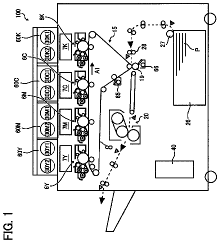
FIG. 1 illustrates the structure of an image forming apparatus according to an exemplary embodiment of the present invention;
FIG. 2 illustrates an example of a process cartridge which is applicable to the image forming apparatus according to the exemplary embodiment;
FIG. 3 illustrates a sectional view of a layer configuration of an electrophotographic photoreceptor in the image forming apparatus according to the exemplary embodiment;
FIG. 4 illustrates a partially sectional view of a layer configuration of another electrophotographic photoreceptor in the image forming apparatus according to the exemplary embodiment;
FIG. 5 illustrates a structure of a state of a cleaning blade in the image forming apparatus according to the exemplary embodiment; and
FIG. 6 illustrates a schematically enlarged sectional view of the cleaning blade in the image forming apparatus according to the exemplary embodiment.
Hereinafter, the exemplary embodiment which is an example of the invention will be described in detail.
Image Forming Apparatus
An image forming apparatus according to an exemplary embodiment includes, an electrophotographic photoreceptor (hereinafter, simply may be referred to as “a photoreceptor”) which includes a photosensitive layer and an overcoat layer on an electroconductive substrate in this order; a charge unit that charges the surface of the photoreceptor; an electrostatic latent image forming unit that forms an electrostatic latent image on the surface of the photoreceptor; a developing unit that develops the electrostatic latent image formed on the surface of the photoreceptor as a toner image with an electrostatic latent image developer; a transfer unit that transfers the toner image to a surface of a recording medium; a cleaning unit that includes a cleaning blade, a tip of which contacts with the photoreceptor to remove a residue on the surface of the photoreceptor; and a fixing unit that fixes the toner image transferred on the recording medium.
In addition, the developing unit contains the electrostatic latent image developer containing a toner.
The toner includes a binder resin containing a crystalline polyester resin, and in which a maximum value (tan δ.sub.P1) of a mechanical loss tangent is from 2 to 2.5 when the complex elastic modulus is in a range of 1×10.sup.6 Pa to 1×10.sup.8 Pa, which is measured at an angular frequency of 6.28 rad/sec and a strain amount of 0.3%.
In the related art, an electrophotographic photoreceptor provided with a photosensitive layer and an overcoat layer on the electroconductive substrate in this order is used for the image forming apparatus. Particularly, from the aspect that the electrophotographic photoreceptor has a long lifespan, and may continuously form images, for example, an electrophotographic photoreceptor (corresponding to the photoreceptor in the image forming apparatus of the exemplary embodiment) including an overcoat layer on a charge generation layer and a charge transport layer (hereinafter, the charge generation layer and the charge transport layer may be collectively referred to as “a photosensitive layer”) is used.
On the other hand, the image forming apparatus according to the electrophotographic method is provided with units such as a charge unit and a transfer unit that perform discharge around the photoreceptor. In accordance with the discharge of the units, in the image forming apparatus, oxygen and nitrogen in the air react with each other so as to generate so-called corona products. When the corona products are attached onto the surface of the photoreceptor, the attached corona products absorb the moisture under the high temperature and high humidity environment (for example, temperature of 28° C. and humidity of 85% RH), so that the surface resistance of the photoreceptor is decreased. For this reason, it is hardly to hold the electrostatic latent image on the photoreceptor, and thus an image flow is likely to occur.
In a case of the image forming apparatus including the electrophotographic photoreceptor in which the overcoat layer is not formed, the corona products are removed from the surface of the electrophotographic photoreceptor through the action such as being scraped together with the surface layer portion of the photosensitive layer by the cleaning blade, and thus the occurrence of the image flow is easily prevent.
However, in the photoreceptor (the specific photoreceptor) including the overcoat layer, the overcoat layer is harder than the photosensitive layer, and thus the action such as being scraped together with the surface layer portion of the photosensitive layer by the cleaning blade does not easily occur. Particularly, in a case where an overcoat layer is formed of a cured material of a composition containing a compound having at least one of an acryloyl group and a methacryloyl group, the overcoat layer becomes harder, and thus the action of scrapping does not easily occur. For this reason, in the image forming apparatus including the specific photoreceptor, the corona products attached on the surface of the overcoat layer are not easily removed by the cleaning blade, and thus the image flow easily occur under the high temperature and high humidity environment.
In contrast, in the image forming apparatus according to the exemplary embodiment, a configuration of combining a photoreceptor including an overcoat layer, a cleaning unit including a cleaning blade, and a toner having the above-described properties is employed.
Here, the fact that the maximum value (tan δ.sub.P1) of a mechanical loss tangent is 2 or more is an indicator that the elasticity is dominant in viscoelasticity of the toner, that is, the toner is hard to be softened.
In the image forming apparatus according to the exemplary embodiment, due to the configuration, the corona products attached on the overcoat layer of the photoreceptor are easily to be removed, and the occurrence of the image flow under the high temperature and high humidity environment is prevented.
Although the reason is not clear, the following reasons may be presumed.
FIG. 6 illustrates an enlarged schematic view of the cleaning blade in the image forming apparatus according to the exemplary embodiment. As illustrated in FIG. 6 , a tip of the cleaning blade 113 is directed to the direction opposite to the rotation direction (direction of arrow A) of the electrophotographic photoreceptor 107 , and concurrently contacts with the electrophotographic photoreceptor 107 . In addition, when the cleaning blade 113 is disposed, a gap (hereinafter, the gap is referred to as “a pre nip portion 113 B”) between the electrophotographic photoreceptor 107 and the cleaning blade 113 is generated on the upstream side of the rotation direction of the electrophotographic photoreceptor 107 from the contact portion between the electrophotographic photoreceptor 107 and the cleaning blade 113 (hereinafter, the contact portion is referred to as “a nip portion 113 A”).
During the rotation of an electrophotographic photoreceptor 107 , by a dynamic frictional force generated between the surface of the electrophotographic photoreceptor 107 and a nip portion 113 A of a cleaning blade 113 , the nip portion 113 A is deformed in a state of being pulled in the rotation direction (direction of arrow A) of the electrophotographic photoreceptor 107 , and a tip angle is formed into a wedge shape. In addition, when the electrophotographic photoreceptor 107 is rotated, a residual matter of toner (hereinafter, the residual matter of toner is also referred to as “a toner dam TD”) is formed in a pre nip portion 113 B.
In the image forming apparatus according to the exemplary embodiment, when an image is formed by the toner, a toner dam TD is formed by residual toner remained after transferring the toner in the prenip portion 113 B.
Here, in the toner dam TD, the toner may be deformed due to the pressure from the cleaning blade 113 . Particularly, when the toner receives frictional heat (rubbing heat) caused between the surface of the photoreceptor and the cleaning blade 113 , the toner is easy to be softened due to the frictional heat, and thus further likely to be deformed. When the toner is deformed in the toner dam TD, the toner dam TD is easily collapsed, and a contact area between the cleaning blade 113 and the surface of the photoreceptor, and the strain of the tip (the nip portion 113 B) of the cleaning blade 113 , which is necessary for the cleaning, are hardly to be ensured. As a result, the scraping properties of the cleaning blade 113 with respect to the residual toner and the surface layer of the electrophotographic photoreceptor 107 are likely to be decreased.
Here, in the exemplary embodiment, as the toner, the toner in which the maximum value (tan δ.sub.P1) of the mechanical loss tangent is in the specific range, that is, the toner which is hard to be softened is employed. Note that, the toner in which the maximum value (tan δ.sub.P1) of the mechanical loss tangent is in the specific range has relatively high hardness.
Due to the above-described properties of the toner, the toner is hard to be softened even when receiving the pressure or the frictional heat from the cleaning blade 113 , and thus is hardly to be deformed. For this reason, the toner in the exemplary embodiment is likely to exist while holding the shape as it is in the toner dam TD. That is, in a state where the entire of toner dams TD are in a good condition (for example, a state where the toner dam TD is formed in a state of being almost uniform in the axial direction of the electrophotographic photoreceptor 107 ).
Accordingly, the contact surface between the cleaning blade 113 and the surface of the photoreceptor is ensured, and the tip (the nip portion 113 B) of the cleaning blade 113 is easily to be distorted. As a result, the scraping properties of the cleaning blade 113 with respect to the residual toner and the surface layer of the electrophotographic photoreceptor 107 are improved.
Particularly, the image forming apparatus according to the exemplary embodiment is provided with the photoreceptor (the electrophotographic photoreceptor 107 ) including the overcoat layer (not shown). In such a photoreceptor, when the corona products are attached onto the overcoat layer, the corona products are hardly to be removed. However, in the exemplary embodiment, the toner which is hard to be softened is used, and the scraping properties of the residual toner and the surface layer of the electrophotographic photoreceptor 107 are improved, and thus the corona products are easily to be removed. As a result, it is considered that the occurrence of the image flow is prevented under the high temperature and high humidity environment.
As described above, in the image forming apparatus according to the exemplary embodiment, the occurrence of the image flow is prevented by using the toner in which the maximum value (tan δ.sub.P1) of the mechanical loss tangent is in the specific range under the high temperature and high humidity environment.
Hereinafter, the image forming apparatus according to the exemplary embodiment will be specifically described.
Toner for Developing Electrostatic Image
First, in the exemplary embodiment, a toner which is contained in a developing device and is used in a developing step will be specifically described.
The toner in the exemplary embodiment contains the binder resin containing the crystalline polyester resin, and has a maximum value (tan δ.sub.P1) of a mechanical loss tangent in a range of 2 to 2.5 when the complex elastic modulus is in a range of 1×10.sup.6 Pa to 1×10.sup.8 Pa, which is measured at an angular frequency of 6.28 rad/sec and a strain amount of 0.3%.
Maximum Value (Tan δ.sub.P1 and Tan δ.sub.P2) of Mechanical Loss Tangent
The maximum value (tan δ.sub.P1) of a mechanical loss tangent of the toner according to the exemplary embodiment is from 2 to 2.5 when the complex elastic modulus is in a range of 1×10.sup.6 Pa to 1×10.sup.8 Pa, which is measured at an angular frequency of 6.28 rad/sec and a strain amount of 0.3%. The maximum value (tan δ.sub.P1) of a mechanical loss tangent of the toner is preferably from 2 to 2.3.
When the toner in which the maximum value (tan δ.sub.P1) of the mechanical loss tangent is 2 or more is used, the occurrence of the image flow is prevented under the high temperature and high humidity environment.
On the other hand, when the maximum value (tan δ.sub.P1) of the mechanical loss tangent is 2.5 or less, the viscosity is prevented from being excessively increased, and thus toner adhesion is prevented.
In addition, in the toner in the exemplary embodiment, the maximum value (tan δ.sub.P2) of the mechanical loss tangent is preferably from 2 to 2.3, and more preferably from 2 to 2.2 when the complex elastic modulus is in a range of 1×10.sup.6 Pa to 1×10.sup.7 Pa, which is measured at an angular frequency of 6.28 rad/sec and a strain amount of 0.3%.
When the maximum value (tan δ.sub.P2) of the mechanical loss tangent is 2 or more, the occurrence of the image flow is prevented under the high temperature and high humidity environment.
On the other hand, when the maximum value (tan δ.sub.2) of the mechanical loss tangent is 2.3 or less, the viscosity is prevented from being excessively increased, and thus toner adhesion is prevented.
Method of Measuring Mechanical Loss Tangent
Here, the calculation of the mechanical loss tangent value is performed based on the dynamic viscoelasticity measured according to a sinusoidal vibration method. In the measurement of the dynamic viscoelasticity, a measuring apparatus ARES manufactured by Rheometric Scientific Inc is used, and the dynamic viscoelasticity is measured by setting toner formed into a tablet is set on a parallel plate having a diameter of 8 mm, and imparting the sinusoidal vibration at a vibration frequency of 6.28 rad/sec to the plate after setting the normal force to be 0. The measurement is started at 60° C., and continued up to 150° C. The measurement time interval is set to be 30 seconds, the temperature rise is set to be 1° C./min, and the strain amount is set to be 0.3% so as to obtain the values of the complex elastic modulus and the mechanical loss tangent, and from the obtained values, the maximum value (tan δ.sub.P1) of the mechanical loss tangent when the complex elastic modulus is in a range of 1×10.sup.6 Pa to 1×10.sup.8 Pa, and the maximum value (tan δ.sub.P2) of the mechanical loss tangent when the complex elastic modulus is in a range of 1×10.sup.6 Pa to 1×10.sup.7 Pa are calculated.
Method of Controlling Maximum Values (Tan δ.sub.P1 and Tan δ.sub.P2) of Mechanical Loss Tangent
A method of controlling the maximum value (tan δ.sub.P1) of the mechanical loss tangent and the maximum value (tan δ.sub.P2) of the mechanical loss tangent of the toner to be in the above-described ranges will be described. The control method is not particularly limited; however, in a case of obtaining toner according to an aggregation and coalescence method described later, a method of using a ester compound (for example, esters formed of higher alcohols having 12 to 30 carbon atoms and higher fatty acids having 12 to 30 carbon atoms, such as stearyl stearate, palmityl palmitate, behenyl behenate, and stearyl montanate; esters formed of higher fatty acids having 12 to 30 carbon atoms and lower monoalcohols, such as butyl stearate, isobutyl behenate, propyl montanate, and 2-ethylhexyl oleate; esters formed of higher fatty acid having 12 to 30 carbon atoms and polyol such as montanic acid monoethylene glycol ester, ethylene glycol distearate, monostearic acid glyceride, monobehenic acid glyceride, tripalmitic acid glyceride, pentaerythritol monobehenate, pentaerythritol dilinoleate, pentaerythritol trioleate, and pentaerythritol tetrastearate; esters formed of higher fatty acids having 12 to 30 carbon atoms and a multimer of polyol, such as diethylene glycol monobehenate, diethylene glycol dibehenate, dipropylene glycol monostearate, distearic acid diglyceride, tetrastearic acid triglyceride, hexabehenic acid tetraglyceride, and decastearic acid deca glyceride; esters formed of higher fatty acids having 12 to 30 carbon atoms and a monomer or a multimer (a short-chain functional group may be contained) of polyol, such as glycerin monoacetomonostearate, glycerin monoacetomonolinoleate, and diglycerin monoacetodistearate; sorbitan higher fatty acid esters such as sorbitan monostearate, sorbitan dibehenate, and sorbitan trioleate; cholesterol higher fatty acid esters such as cholesteryl stearate, cholesteryl oleate, and cholesteryl linoleate) in a mixed dispersion in which a resin particle dispersion and the like are mixed with each other, and adjusting the amount at the time of forming aggregated particles.
The ester compound such as stearyl stearate is attached to the surface of the resin particle at the time of forming the aggregated particles, and reduces an apparent glass transition temperature of the surface so as to improve the stability of the aggregated particles and the responsiveness to heat of particles attached to the surface of resin. For this reason, it is considered that the maximum value (tan δ.sub.P1 and tan δ.sub.P2) of the mechanical loss tangent under the above-described conditions may be increased.
In addition, the ester compound may be set as an ester compound dispersion in which the ester compound is dispersed in advance, and the ester compound dispersion may be added into the mixture dispersion at the time of forming the aggregated particles.
In addition, examples of the control method also include a method of incorporating a metal oxide (for example, water glass, silica, alumina, titania, calcium carbonate, magnesium carbonate, tricalcium phosphate, and cerium oxide) in the mixed dispersion, with the amount at the time of forming aggregated particles being adjusted.
The metal oxide such as water glass tends to exist at an appropriate distance in the resin particle at the time of forming the aggregated particles, and therefore, acts to lower the viscosity of the resin molecules when being heated during the fixing. For this reason, the maximum values (tan δ.sub.P1 and tan δ.sub.P2) of the mechanical loss tangent are increased under the above-described conditions.
As a resin particle dispersion using the aggregation and coalescence method, a dispersion in which crystalline resin-amorphous resin mixed particles are dispersed is preferably used. The dispersion is obtained in such a manner that a crystalline resin containing a crystalline polyester resin and an amorphous resin are dispersed in a dispersion medium, and then, the dispersion medium containing the crystalline resin and the amorphous resin is subjected to the phase inversion emulsification. Since both the crystalline resin and the amorphous resin are dispersed in the dispersion medium and then the dispersion medium is subjected to the phase inversion emulsification, it is possible to obtain well-mixed crystalline resin-amorphous resin mixed particles as compared with a case where the crystalline resin and amorphous resin are independently dispersed in the dispersion mediums to prepare the respective dispersions and the dispersions are mixed and then subjected to the phase inversion emulsification.
Further, the maximum value (tan δ.sub.P1 and tan δ.sub.P2) of the mechanical loss tangent is also adjusted by the ratio of the crystalline resin to the amorphous resin, the molecular amount of the crystalline resin or the amorphous resin, and the crosslinking degree.
Dynamic Complex Viscosity (η*.sub.−30 and η*.sub.−10)
The dynamic complex viscosity (η*.sub.−30) of the toner according to the exemplary embodiment is preferably 3×10.sup.7 Pa.Math.s or more at a temperature of (the melting temperature of a crystalline polyester resin contained in the toner −30° C.), and the dynamic complex viscosity (η*.sub.−10) is preferably in a range of 1×10.sup.6 Pa.Math.s to 5×10.sup.7 Pa.Math.s at a temperature of (the melting temperature of the crystalline polyester resin −10° C.).
The dynamic complex viscosity (η*.sub.−30) of the toner at a temperature of (the melting temperature of the crystalline polyester resin −30°) may be regarded as the dynamic complex viscosity of the toner in a state before being melted, that is, in a solid state; on the other hand, the dynamic complex viscosity (η*.sub.−10) at a temperature of (the melting temperature of the crystalline polyester resin −10° C.) may be regarded as the dynamic complex viscosity of the toner in a state of starting to be melted. In addition, in the toner, the fact that the dynamic complex viscosity (η*.sub.−30) in the solid state is equal to or greater than the above-described lower limit value and the dynamic complex viscosity (η*.sub.−10) in the state of starting to be melted is in the above-described range is an indicator that the toner is hard to be melted.
When the dynamic complex viscosities η*.sub.−30 and η*.sub.−10 of the toner are in the above-described ranges, respectively, the toner is further hard to be softened even when receiving the pressure or the frictional heat from the cleaning blade, and thus is hardly to be deformed. Accordingly, the toner is likely to exist while holding the shape as it is in the toner dam TD. As a result, the contact area between the cleaning blade and the surface of the photoreceptor is easily ensured, and the scraping properties of the cleaning blade with respect to the residual toner and the surface layer of the photoreceptor are improved.
When the dynamic complex viscosity (η*.sub.−30) of the toner at a temperature of (the melting temperature of the crystalline polyester resin −30° C.) is 3×10.sup.7 Pa.Math.s or more, the compatibility of the crystalline polyester resin with the other resin is deteriorated, and thus a partial decrease in the glass transition temperature of the resin is prevented. For this reason, a difference hardly appears in the adhesion of the external additive on the toner surface, and for example, the occurrence of transfer unevenness is prevented, which is a preferable point.
Further, when the dynamic complex viscosity (η*.sub.−10) at a temperature of (the melting temperature of the crystalline polyester resin −10° C.) is 1×10.sup.6 Pa.Math.s or more, the toner is hardly to be melted even at the temperature close to the melting temperature, and the toner is easily prevented from being softened when receiving the frictional heat.
On the other hand, when the dynamic complex viscosity (η*.sub.−10) of the toner at a temperature of (the melting temperature of the crystalline polyester resin −10° C.) is 5×10.sup.7 Pa.Math.s or less, the fixing temperature of the entire toners may be decreased to the proper temperature, and the surface gloss is appropriately controlled. Thus, it is possible to prevent the difference in gloss caused by the difference in the applied toner amount, which is a preferable point.
Note that, the dynamic complex viscosity (η*.sub.−10)) under the condition of a temperature of (the melting temperature of the crystalline polyester resin −10° C.) is preferably in a range of 2×10.sup.6 Pa.Math.s to 3×10.sup.7 Pa.Math.s, and more preferably in a range of 4×10.sup.6 Pa.Math.s to 2×10.sup.7 Pa.Math.s.
In addition, the dynamic complex viscosity (η*.sub.−30) at a temperature of (the melting temperature of the crystalline polyester resin −30° C.) is preferably 1×10.sup.8 Pa.Math.s or more, and more preferably 5×10.sup.8 Pa.Math.s or more.
Method of Measuring Dynamic Complex Viscosity
The measurement of the dynamic complex viscosity (η*) is performed in such a manner that by using a rheometer, under the condition of frequency of 1 rad/second, and heating is performed at a heating rate of 1° C./minute from the melting temperature of the crystalline polyester resin contained in the toner, and the dynamic complex viscosity is measured for each degree. A measurement strain is set to be equal to or less than 20%, and parallel plates of 8 mmφ and 25 mmφ are separately used in accordance with a measurement torque.
Control Method of Dynamic Complex Viscosity (η*.sub.−30 and η*.sub.−10)
A method of controlling the dynamic complex viscosity (η*.sub.−30) and the dynamic complex viscosity (η*.sub.−10) in the toner to be in the above-described ranges is not particularly limited, and for example, in a case of a toner having a core-shell structure, there is a method by adjusting the ratio of the binder resin in a core and a shell and the molecular weight of the binder resin, particularly the molecular weight of the crystalline resin contained in the core. In addition, examples of the above-described method also include a method of adjusting the acid value of the crystalline resin, the presence or absence of the addition of a coagulant used in the aggregation and coalescence step at the time of preparing the toner, or a kind thereof.
From the viwepoint of controlling the dynamic complex viscosity (η*.sub.−30 and η*.sub.−10), a method of incorporating an ester compound such as stearyl stearate as described above and adjusting the amount thereof, and a method of incorporating the metal oxide such as the above-described water glass and adjusting the amount thereof are preferably used.
Further, from the viewpoint of controlling the dynamic complex viscosity (η*.sub.−30 and η*.sub.−10), as a resin particle dispersion using the aggregation and coalescence method, a dispersion in which crystalline resin-amorphous resin mixed particles are dispersed is preferably used. The dispersion is obtained by dispersing a crystalline resin containing a crystalline polyester resin and an amorphous resin in a dispersion medium, and then, performing the phase inversion emulsification on the dispersion medium.
Next, components of the toner in the exemplary embodiment will be described.
The toner according to the exemplary embodiment is formed of toner particles, and if necessary, an external additive.
Toner Particle
The toner particle is formed of a binder resin, and if necessary, a colorant, a release agent, and other additives. In addition, the binder resin contains at least a crystalline polyester resin.
Binder Resin
Examples of the binder resin include vinyl resins formed of homopolymer of monomers such as styrenes (for example, styrene, para-chloro styrene, and α-methyl styrene), (meth)acrylic esters (for example, methyl acrylate, ethyl acrylate, n-propyl acrylate, n-butyl acrylate, lauryl acrylate, 2-ethylhexyl acrylate, methyl methacrylate, ethyl methacrylate, n-propyl methacrylate, lauryl methacrylate, and 2-ethylhexyl methacrylate), ethylenic unsaturated nitriles (for example, acrylonitrile, and methacrylonitrile), vinyl ethers (for example, vinyl methyl ether, and vinyl isobutyl ether), vinyl ketones (for example, vinyl methyl ketone, vinyl ethyl ketone, and vinyl isopropenyl ketone), and olefins (for example, ethylene, propylene, and butadiene), or copolymers obtained by combining two or more kinds of these monomers.
As the binder resin, there are also exemplified non-vinyl resins such as an epoxy resin, a polyester resin, a polyurethane resin, a polyamide resin, a cellulose resin, a polyether resin, and a modified rosin, a mixture thereof with the above-described vinyl resins, or a graft polymer obtained by polymerizing a vinyl monomer with the coexistence of such non-vinyl resins.
These binder resins may be used singly or in combination of two or more types thereof.
Examples of the crystalline polyester resin include a well-known polyester resin. The crystalline polyester resin may be used in combination with the amorphous polyester resin. The content of the crystalline polyester resin may be in a range of 2% by weight to 40% by weight (preferably in a range of 2% by weight to 20% by weight) with respect to the entirety of the binder resin.
Note that, “crystalline” of the resin means having not a stepwise endothermic change but a clear endothermic peak in the differential scanning calorimetry (DSC), and specifically, means that the half-value width of the endothermic peak is within 10° C. when measured at a heating rate of 10 (° C./min).
On the other hand, “amorphous” of the resin means that the half value width is higher than 10° C., the endothermic change is stepwise, or a clear endothermic peak is not recognized.
Amorphous Polyester Resin
Examples of the amorphous polyester resin include condensation polymers of polyvalent carboxylic acid and polyol. A commercially available product or a synthesized product may be used as the amorphous polyester resin.
Examples of the polyvalent carboxylic acid include aliphatic dicarboxylic acid (for example, oxalic acid, malonic acid, maleic acid, fumaric acid, citraconic acid, itaconic acid, glutaconic acid, succinic acid, alkenyl succinic acid, adipic acid, and sebacic acid), alicyclic dicarboxylic acid (for example, cyclohexane dicarboxylic acid), aromatic dicarboxylic acid (for example, terephthalic acid, isophthalic acid, phthalic acid, and naphthalene dicarboxylic acid), an anhydride thereof, or lower alkyl esters (having, for example, from 1 to 5 carbon atoms) thereof. Among these, for example, aromatic dicarboxylic acids are preferably used as the polyvalent carboxylic acid.
As the polyvalent carboxylic acid, tri- or higher-valent carboxylic acid having a crosslinked structure or a branched structure may be used in combination with dicarboxylic acid. Examples of the tri- or higher-valent carboxylic acid include trimellitic acid, pyromellitic acid, anhydrides thereof, or lower alkyl esters (having, for example, 1 to 5 carbon atoms) thereof.
The polyvalent carboxylic acid may be used singly or in combination of two or more types thereof.
Examples of the polyol include aliphatic diol (for example, ethylene glycol, diethylene glycol, triethylene glycol, propylene glycol, butanediol, hexanediol, and neopentyl glycol), alicyclic diol (for example, cyclohexanediol, cyclohexane dimethanol, and hydrogenated bisphenol A), aromatic diol (for example, an ethylene oxide adduct of bisphenol A, and a propylene oxide adduct of bisphenol A). Among these, for example, aromatic diols and alicyclic diols are preferably used, and aromatic diols are more preferably used as the polyol.
As the polyol, a tri- or higher-valent polyol having a crosslinked structure or a branched structure may be used in combination with diol. Examples of the tri- or higher-valent polyol include glycerin, trimethylolpropane, and pentaerythritol.
The polyol may be used singly or in combination of two or more types thereof.
The glass transition temperature (Tg) of the amorphous polyester resin is preferably from 50° C. to 80° C., and more preferably from 50° C. to 65° C.
The glass transition temperature is obtained from a DSC curve obtained by differential scanning calorimetry (DSC). More specifically, the glass transition temperature is obtained from “Extrapolated glass transition onset temperature” described in the method of obtaining a glass transition temperature in JIS K 7121-1987 “Testing methods for transition temperatures of plastics”.
The weight average molecular weight (Mw) of the amorphous polyester resin is preferably from 5,000 to 1,000,000, and more preferably from 7,000 to 500,000.
The number average molecular weight (Mn) of the amorphous polyester resin is preferably from 2,000 to 100,000.
The molecular weight distribution Mw/Mn of the amorphous polyester resin is preferably from 1.5 to 100, and more preferably from 2 to 60.
The weight average molecular weight and the number average molecular weight are measured by gel permeation chromatography (GPC). The molecular weight measurement by GPC is performed using GPC: HLC-8120 GPC, manufactured by Tosoh Corporation as a measuring device, column: TSK gel Super HM-M (15 cm), manufactured by Tosoh Corporation, and a THF solvent. The weight average molecular weight and the number average molecular weight are calculated by using a molecular weight calibration curve plotted from a monodisperse polystyrene standard sample from the results of the foregoing measurement.
A known preparing method may be used to prepare the amorphous polyester resin. Specific examples thereof include a method of conducting a reaction at a polymerization temperature set to be in a range of 180° C. to 230° C., if necessary, under reduced pressure in the reaction system, while removing water or an alcohol generated during condensation.
When monomers of the raw materials are not dissolved or compatibilized under a reaction temperature, a high-boiling-point solvent may be added as a solubilizing agent to dissolve the monomers. In this case, a polycondensation reaction is conducted while distilling away the solubilizing agent. When a monomer having poor compatibility is present in a copolymerization reaction, the monomer having poor compatibility and an acid or an alcohol to be polycondensed with the monomer may be previously condensed and then polycondensed with the major component.
Crystalline Polyester Resin
Examples of the crystalline polyester resin include a polycondensate of polyvalent carboxylic acid and polyol. Note that, as the crystalline polyester resin, a commercially available product may be used or, synthesized product may be used.
Here, the crystalline polyester resin easily forms a crystalline structure, and thus a polycondensate obtained by using a polymerizable monomer having a linear aliphatic group rather than a polymerizable monomer having an aromatic group is preferable.
Examples of the polyvalent carboxylic acid include aliphatic dicarboxylic acid (for example, oxalic acid, succinic acid, glutaric acid, adipic acid, suberic acid, azelaic acid, sebacic acid, 1,9-nonanedicarboxylic acid, 1,10-decanedicarboxylic acid, 1,12-dodecanedicarboxylic acid, 1,14-tetradecanedicarboxylic acid, and 1,18-octadecanedicarboxylic acid), aromatic dicarboxylic acid (for example, dibasic acid such as phthalic acid, isophthalic acid, terephthalic acid, or naphthalene-2,6-dicarboxylic acid), anhydrides thereof, or lower alkyl esters (having, for example, from 1 to 5 carbon atoms) thereof.
As the polyvalent carboxylic acid, tri- or higher-valent carboxylic acid having a crosslinked structure or a branched structure may be used in combination with dicarboxylic acid. Examples of tri-valent carboxylic acid include aromatic carboxylic acids (for example, 1,2,3-benzenetricarboxylic acid, 1,2,4-benzenetricarboxylic acid, 1,2,4-naphthalenetricarboxylic acid), anhydrides thereof, or lower alkyl esters (having, for example, from 1 to 5 carbon atoms) thereof.
As the polyvalent carboxylic acid, a dicarboxylic acid having a sulfonic acid group or a dicarboxylic acid having an ethylenic double bond may be used together with the dicarboxylic acid.
The polyvalent carboxylic acid may be used singly or in combination of two or more types thereof.
Examples of the polyol include an aliphatic diol (for example, a linear aliphatic diol having a carbon number of 7 to 20 in the main chain portion). Examples of the aliphatic diol include ethylene glycol, 1,3-propanediol, 1,4-butanediol, 1,5-pentanediol, 1,6-hexanediol, 1,7-heptanediol, 1,8-octanediol, 1,9-nonanediol, 1,10-decanediol, 1,11-undecanediol, 1,12-dodecanediol, 1,13-tridecanediol, 1,14-tetradecanediol, 1,18-octadecanediol, and 1,14-eicosanedecanediol. Among them, examples of the aliphatic diol preferably include 1,8-octanediol, 1,9-nonanediol, and 1,10-decanediol.
As the polyol, a tri- or higher-valent polyol having a crosslinked structure or a branched structure may be used in combination with diol. Examples of the tri- or higher-valent polyol include glycerin, trimethylolethane, trimethylolpropane, and pentaerythritol.
The polyol may be used singly or in combination of two or more types thereof.
Here, polyol may have the aliphatic diol of which the content is preferably 80 mol % or more, and further preferably 90 mol % or more.
The melting temperature of the crystalline polyester resin is preferably in a range of 50° C. to 100° C., is further preferably in a range of 55° C. to 90° C., and is still further in a range of 60° C. to 85° C.
Note that, the melting temperature is obtained from a DSC curve obtained by differential scanning calorimetry (DSC), and specifically obtained from “Melting peak temperature” described in the method of obtaining a melting temperature in JIS K 7121-1987 “Testing methods for transition temperatures of plastics”.
The weight average molecular weight (Mw) of the crystalline polyester resin is preferably in a range of 6,000 to 35,000.
The crystalline polyester resin may be obtained according to a well-known preparing method similarly to the amorphous polyester resin.
The content of the binder resin is preferably from 40% by weight to 95% by weight, more preferably from 50% by weight to 90% by weight, and most preferably from 60% by weight to 85% by weight, with respect to the entirety of the toner particles.
Colorant
The description continues in the full USPTO document.
About 6,139 words. The USPTO PDF has it with every drawing.
Fees are due 3.5, 7.5 and 11.5 years after grant. This patent expired on May 29, 2026, so the fee marked "not paid" was the one that went unpaid.
IMAGE FORMING APPARATUS
Filed Feb 2017 · published Jan 2018Image forming apparatus
Filed Feb 2017 · granted May 2018Earlier publications, parents and continuations. None of them can still be enforced, or this patent would not be listed.
Prior art cited by the examiner or applicant. Useful when you check your own idea for novelty.
Everything on this page comes from the documents linked above.