Lapsed, fee not paid4 drawings
Industrial Equipment · US 9,982,770 B2
Manual transmission oil feeder
A transmission oil feeder for a motor vehicle includes an input member defining a rotating shaft.
US 9,982,774 B1 · Assignee: GM GLOBAL TECHNOLOGY OPERATIONS LLC · Inventors: Jin; Timothy Z et al.
Sheet 1 of 9 from the published document. All sheets in the USPTO PDF
A hydraulic control system for a motor vehicle transmission includes a pressure regulation subsystem and a manual valve assembly in fluid communication with the pressure regulation subsystem. The manual valve assembly is moveable between at least park, neutral, drive, and reverse positions. A default disable valve assembly is in fluid communication with the manual valve assembly, a default disable solenoid valve assembly, and a default select valve assembly. A one-way valve may be provided to permit hydraulic fluid to flow to a second-priority hydraulic circuit when in a default mode of operation. A combined main regulation and priority valve may be provided to pressurize line pressure as a first priority, pressurize the second-priority hydraulic circuit as a second priority, and to feed excess pressure to a decrease-pressure circuit as a third priority.
1 of 9 drawing sheets so far from the published document, cropped to the drawing. Every sheet is in the USPTO PDF.
What the patent claimed, word for word. All of it is now free to use.
This disclosure relates to a hydraulic control system for an automatic transmission, and more particularly to a hydraulic control system for an automatic transmission having a manual valve and two forward and one reverse default gear states.
A typical automatic transmission includes a hydraulic control system that is employed to provide cooling and lubrication to components within the transmission and to actuate a plurality of torque transmitting devices. These torque transmitting devices may be, for example, friction clutches and brakes arranged with gear sets or in a torque converter. The conventional hydraulic control system typically includes a main pump that provides a pressurized fluid, such as oil, to a plurality of valves and solenoids within a valve body. The main pump is driven by the engine of the motor vehicle. The valves and solenoids are operable to direct the pressurized hydraulic fluid through a hydraulic fluid circuit to various subsystems including lubrication subsystems, cooler subsystems, torque converter clutch control subsystems, and shift actuator subsystems that include actuators that engage the torque transmitting devices. The pressurized hydraulic fluid delivered to the shift actuators is used to engage or disengage the torque transmitting devices in order to obtain different gear ratios.
While previous hydraulic control systems are useful for their intended purpose, the need exists for new and improved hydraulic control system configurations within transmissions which exhibit improved performance, especially during default conditions. A default condition is a hydraulic state that the transmission experiences in the absence of electronic control. A transmission in default no longer has the capability to electronically command solenoids to achieve the desired gear state. The default condition may have been intentionally commanded (e.g. when diagnostics indicate corrupt solenoid drivers, corrupt controllers, controller shutdown at high temperatures) or can occur unintentionally due to a hardware failure (e.g. controller failure, wiring harness failure, solenoid driver failure). For some transmission configurations, the hydraulic control system shifts the transmission to neutral during a default condition. Accordingly, there is a need for an improved, cost-effective hydraulic control system for use in a hydraulically actuated automatic transmission that provides forward and reverse driving states during default conditions.
In one form, which may be combined with or separate from other forms disclosed herein, a hydraulic control system for a transmission of a motor vehicle is provided. The hydraulic control system includes a pressure regulation subsystem in fluid communication with a pump, the pressure regulation subsystem being configured to provide pressurized hydraulic fluid. A second-priority hydraulic circuit is in fluid communication with the pressure regulation subsystem. The second-priority hydraulic circuit includes one or more of: a cooling hydraulic subsystem, a lubrication hydraulic subsystem, and a torque converter control subsystem. A manual valve assembly is in fluid communication with the pressure regulation subsystem. The manual valve assembly is moveable between at least a park position, a neutral position, a drive position, and a reverse position. A default disable valve assembly is in fluid communication with the manual valve assembly. A default disable solenoid valve assembly is in fluid communication with the default disable valve assembly. The default disable solenoid valve assembly is configured to enable the default disable valve assembly to enable a plurality of default modes of operation. A default select valve assembly is in fluid communication with the default disable valve assembly. The default select valve assembly is configured to select between at least a portion of the plurality of default modes of operation. A blow-off valve is in fluid communication with the default select valve assembly, and the blow-off valve is configured to limit line pressure during the plurality of default modes of operation. A one-way valve is configured to permit a portion of the pressurized hydraulic fluid to flow to the second-priority hydraulic circuit when the hydraulic control system is in a default mode of operation.
In another form, which may be combined with or separate from the other forms disclosed herein, a hydraulic control system for a transmission of a motor vehicle is provided. The hydraulic control system includes a pressure regulation subsystem in fluid communication with a pump. The pressure regulation subsystem includes a combined main regulation and priority valve configured to provide pressurized hydraulic fluid. A second-priority hydraulic circuit is in fluid communication with the pressure regulation subsystem. The second-priority hydraulic circuit includes at least one of the following: a cooling hydraulic subsystem, a lubrication hydraulic subsystem, and a torque converter control subsystem. The combined main regulation and priority valve is configured to pressurize line pressure in the hydraulic control system as a first priority, to pressurize the second-priority hydraulic circuit as a second priority, and to feed excess pressure to a decrease-pressure circuit as a third priority. A manual valve assembly is in fluid communication with the pressure regulation subsystem. The manual valve assembly is moveable between at least a park position, a neutral position, a drive position, and a reverse position. A default disable valve assembly is in fluid communication with the manual valve assembly. A default disable solenoid valve assembly is in fluid communication with the default disable valve assembly. The default disable solenoid valve assembly is configured to enable the default disable valve assembly to enable a plurality of default modes of operation. A default select valve assembly is in fluid communication with the default disable valve assembly. The default select valve assembly is configured to select between at least a portion of the plurality of default modes of operation. A plurality of clutch regulation valve assemblies is in fluid communication with the pressure regulation subsystem, the manual valve assembly, the default disable valve assembly, and the default select valve assembly. The plurality of clutch regulation valve assemblies is configured to engage a plurality of torque-transmitting mechanisms.
Additional features may be optionally provided, including but not limited to the following: wherein the pressure regulation subsystem comprises a combined main regulation and priority valve; the combined main regulation and priority valve being configured to pressurize line pressure in the hydraulic control system as a first priority, to pressurize the second-priority hydraulic circuit as a second priority, and to feed excess pressure to a decrease-pressure circuit as a third priority; the hydraulic control system further comprising a plurality of clutch regulation valve assemblies in fluid communication with the pressure regulation subsystem, the manual valve assembly, the default disable valve assembly, and the default select valve assembly; wherein the plurality of clutch regulation valve assemblies is configured to engage a plurality of torque-transmitting mechanisms; wherein each of the plurality of clutch regulation valve assemblies includes an exhaust port configured to exhaust a torque-transmitting mechanism of the plurality of torque-transmitting mechanisms in a normal mode of operation; wherein each of the exhaust ports is in selective communication with the default disable valve assembly and the default select valve assembly; each exhaust port being configured to selectively receive pressurized hydraulic fluid in at least one default mode of the plurality of default modes of operation; wherein each exhaust port of each clutch regulation valve assembly of the plurality of clutch regulation valve assemblies selectively communicates with at least one of the default disable valve assembly and the default select valve assembly via at least one three-way valve of a plurality of three-way valves, where the three-way valves may be three-way ball check valves; wherein the default disable valve assembly is configured to selectively communicate pressurized hydraulic fluid from the manual valve assembly to the default select valve assembly when in the drive position; and the default select valve assembly being configured to selectively communicate pressurized hydraulic fluid to a first subset of the plurality of clutch regulation valve assemblies to provide a low default gear ratio and to a second subset of the plurality of clutch regulation valve assemblies to provide a high default gear ratio, the high default gear ratio having a higher gear speed than the low default gear ratio.
Further additional features may be provided, including but not limited to the following: wherein the default disable valve assembly is configured to selectively communicate pressurized hydraulic fluid from the manual valve assembly to the plurality of three-way valves to provide a reverse default gear ratio; wherein a position of the default select valve assembly is configured to be controlled by pressurized hydraulic fluid from the manual valve assembly and a spring when engaged in the high default gear ratio, from at least one of the clutch regulation valve assemblies of the plurality of clutch regulation valve assemblies and the spring when engaged in the low default gear ratio, and from the manual valve assembly and at least one of the clutch regulation valve assemblies of the plurality of clutch regulation valve assemblies when engaged in the reverse default gear ratio; wherein the plurality of torque-transmitting mechanisms includes six torque-transmitting mechanisms selectively engageable in combinations of four to provide at least 10 forward speed ratios and one reverse speed ratio; the second-priority hydraulic circuit comprising the torque converter control subsystem; and the hydraulic control system being free of an anti-backflow valve in fluid communication with the combined main regulation and priority valve.
Even further additional features may be provided, including but not limited to the following: the manual valve assembly being configured to selectively provide a drive fluid signal and a reverse fluid signal from the pressurized hydraulic fluid; the default disable valve assembly being configured to receive the drive fluid signal and the reverse fluid signal; the default disable solenoid valve assembly being configured to selectively engage the default disable valve assembly through an ON signal and an OFF signal; the default disable valve assembly having a first position configured to terminate the drive fluid signal and the reverse fluid signal when the default disable valve assembly receives the ON signal from the default disable solenoid valve assembly; the default disable valve assembly having a second position configured to communicate the drive fluid signal and the reverse fluid signal to a drive default fluid signal and a reverse default fluid signal when the default disable valve assembly receives the OFF signal from the default disable solenoid valve assembly; the default select valve assembly configured to receive the drive default fluid signal; the default select valve assembly having a first position configured to communicate the drive default fluid signal to a first exhaust signal and a second position configured to communicate the drive default fluid signal to a second exhaust signal; the plurality of clutch regulation valve assemblies being selectively in fluid communication with the first exhaust signal, the second exhaust signal, the drive default signal, and the reverse default signal; the plurality of default modes of operation including a low forward default gear ratio, a high forward default gear ratio, and a reverse default gear ratio; the default select valve assembly being configured to select between the low forward default gear ratio and the high forward default gear ratio.
Additional features may be provided, including but not limited to the following: in the low forward default gear ratio, the first exhaust signal communicates with the exhaust port of a first clutch regulation valve assembly and the exhaust port of a second clutch regulation valve assembly of the plurality of clutch regulation valve assemblies via a first three-way valve of the plurality of three-way valves, and the drive default signal communicates with the exhaust port of a third clutch regulation valve assembly and the exhaust port of a fourth clutch regulation valve assembly of the plurality of clutch regulation valve assemblies via a second three-way valve of the plurality of three-way valves; in the high forward default gear ratio, the second exhaust signal communicates with the exhaust port of a fifth clutch regulation valve assembly and the exhaust port of a sixth clutch regulation valve assembly of the plurality of clutch regulation valve assemblies via a third three-way valve of the plurality of three-way valves, and the drive default signal communicates with the exhaust port of the third clutch regulation valve assembly and the exhaust port of the sixth clutch regulation valve assembly via the second three-way valve; in the reverse default gear ratio, the reverse default signal communicates with the exhaust port of the first clutch regulation valve assembly and the exhaust port of the second clutch regulation valve assembly via the first three-way valve, the reverse default signal communicates with the exhaust port of the fourth clutch regulation valve assembly via the second three-way valve, and the reverse default signal communicates with the exhaust port of the sixth clutch regulation valve assembly via the third three-way valve; wherein the first exhaust signal and drive default signal are configured to selectively engage a first subset of the plurality of torque-transmitting mechanisms to produce the low forward default gear ratio; and the second exhaust signal and drive default signal are configured to selectively engage a second subset of the plurality of torque-transmitting mechanisms to produce the high forward default gear ratio when the hydraulic control system is in a default mode of operation of the plurality of default modes of operation and the manual valve assembly is in the drive position.
Further additional features may be provided, including but not limited to the following: wherein the low forward default gear ratio is configured to be automatically engaged when at least one of the following occurs: 1) after an operator of the motor vehicle performs a key cycle on the motor vehicle while the default disable solenoid valve assembly provides the OFF signal; and 2) when the operator of the motor vehicle moves the manual valve assembly from the drive position to the reverse position and back to the drive position; wherein the reverse default signal is configured to engage a third subset of torque-transmitting mechanisms to produce the reverse default gear ratio when the hydraulic control system is in a default mode of operation of the plurality of default modes of operation and the manual valve assembly is in the reverse position; and wherein the low forward default gear ratio is a second gear ratio and the high forward default gear ratio is a seventh gear ratio
Further areas of applicability will become apparent from the description provided herein. It should be understood that the description and specific examples are intended for purposes of illustration only and are not intended to limit the scope of the present disclosure.
The drawings described herein are for illustration purposes only and are not intended to limit the scope of the present disclosure in any way.
FIG. 1 is a is a schematic diagram of an exemplary powertrain in a motor vehicle according to the principles of the present disclosure;
FIG. 2A is a diagram of a portion of a hydraulic control system according to the principles of the present disclosure;
FIG. 2B is a diagram of a portion of a hydraulic control system according to the principles of the present disclosure;
FIG. 2C is a diagram of a portion of a hydraulic control system according to the principles of the present disclosure;
FIG. 2D is a diagram of a portion of a hydraulic control system according to the principles of the present disclosure;
FIG. 2E is a diagram of a portion of a hydraulic control system according to the principles of the present disclosure;
FIG. 2F is a diagram of a portion of a hydraulic control system according to the principles of the present disclosure;
FIG. 3 is a diagram of a portion of the hydraulic control system in a default second forward gear condition according to the principles of the present disclosure;
FIG. 4 is a diagram of a portion of the hydraulic control system in a default seventh forward gear condition according to the principles of the present disclosure; and
FIG. 5 is a diagram of a portion of the hydraulic control system in a default reverse condition according to the principles of the present disclosure.
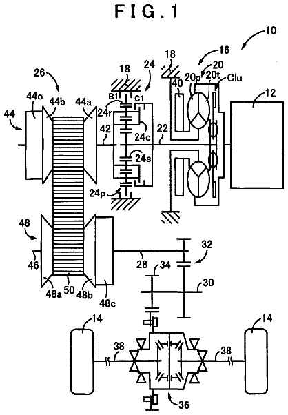
With reference to FIG. 1 , a motor vehicle is shown and generally indicated by reference number 8 . The motor vehicle 8 is illustrated as a passenger car, but it should be appreciated that the motor vehicle 8 may be any type of vehicle, such as a truck, van, sport-utility vehicle, etc. The motor vehicle 8 includes an exemplary propulsion system 10 . It should be appreciated at the outset that while a rear-wheel drive propulsion system 10 has been illustrated, the motor vehicle 8 may have a front-wheel drive propulsion system without departing from the spirit and scope of the present disclosure. The propulsion system 10 generally includes an engine 12 interconnected with a transmission 14 .
The engine 12 may be a conventional internal combustion engine or an electric engine, hybrid engine, or any other type of prime mover, without departing from the spirit and scope of the present disclosure. The engine 12 supplies a driving torque to the transmission 14 through a flexplate 15 or other connecting device that is connected to a starting device 16 . The starting device 16 may be a hydrodynamic device, such as a fluid coupling or torque converter, a wet dual clutch, or an electric motor, by way of example. It should be appreciated that any starting device 16 between the engine 12 and the transmission 14 may be employed, including a dry launch clutch.
The transmission 14 has a typically cast, metal housing 18 which encloses and protects the various components of the transmission 14 . The housing 18 includes a variety of apertures, passageways, shoulders, and flanges that position and support these components. Generally speaking, the transmission 14 includes a transmission input shaft 20 and a transmission output shaft 22 . Disposed between the transmission input shaft 20 and the transmission output shaft 22 is a gear and clutch arrangement 24 . The transmission input shaft 20 is functionally interconnected with the engine 12 via the starting device 16 and receives input torque or power from the engine 12 . Accordingly, the transmission input shaft 20 may be a turbine shaft in the case where the starting device 16 is a hydrodynamic device, dual input shafts where the starting device 16 is dual clutch, or a drive shaft where the starting device 16 is an electric motor. The transmission output shaft 22 is preferably connected with a final drive unit 26 which includes, for example, a propshaft 28 , a differential assembly 30 , and drive axles 32 connected to wheels 33 . The transmission input shaft 20 is coupled to and provides drive torque to the gear and clutch arrangement 24 .
The gear and clutch arrangement 24 includes a plurality of gear sets, six torque transmitting mechanisms, such as clutches or brakes, indicated schematically by reference letters AA, BB, CC, DD, EE, FF, and a plurality of shafts. The plurality of gear sets may include individual intermeshing gears, such as planetary gear sets, that are connected to or selectively connectable to the plurality of shafts through the selective actuation of the plurality of clutches/brakes. The plurality of shafts may include layshafts or countershafts, sleeve and center shafts, reverse or idle shafts, or combinations thereof. The torque transmitting mechanisms AA-FF are selectively engageable in combinations of four to initiate at least one of ten forward gear or speed ratios and one reverse gear or speed ratio by selectively coupling individual gears within the plurality of gear sets to the plurality of shafts. In one example, torque transmitting mechanisms AA and BB are friction brakes while torque transmitting mechanisms CC-FF are friction clutches. It should be appreciated that the specific arrangement and number of the gear sets and shafts within the transmission 14 may vary without departing from the spirit and scope of the present disclosure.
The motor vehicle 8 includes a transmission control module 40 . The transmission control module 40 is preferably a non-generalized, electronic control device having a preprogrammed digital computer or processor, control logic or circuits, memory used to store data, and at least one I/O peripheral. The control logic includes or enables a plurality of logic routines for monitoring, manipulating, and generating data and control signals. The transmission control module 40 controls the actuation of the torque transmitting mechanisms AA-FF via a hydraulic control system 100 .
The hydraulic control system 100 is disposed within a valve body 101 that contains and houses, via fluid paths and valve bores, most of the components of the hydraulic control system 100 . These components include, but are not limited to, pressure regulation valves, directional valves, solenoids, etc. The valve body 101 may be attached to a bottom of the transmission housing 18 in rear-wheel drive transmissions or attached to a front of the transmission housing 18 in front-wheel drive transmissions. The hydraulic control system 100 is operable to selectively engage the clutches/brakes AA-FF and to provide cooling and lubrication to the transmission 14 by selectively communicating a hydraulic fluid from a sump 102 under pressure from an engine driven pump 104 . The pump 104 may be driven by the engine 12 or by an auxiliary engine or electric motor.
With reference to FIGS. 2A-F , a portion of the hydraulic control system 100 is illustrated. The hydraulic control system 100 generally includes a plurality of interconnected or hydraulically communicating subsystems including a pressure regulator subsystem 106 and a clutch control subsystem 108 . The hydraulic control system 100 may also include various other subsystems or modules not illustrated in the drawings.
The pressure regulator subsystem 106 is operable to provide and regulate pressurized hydraulic fluid, such as transmission oil, throughout the hydraulic control system 100 . The pressure regulator subsystem 106 draws hydraulic fluid from the sump 102 . The sump 102 is a tank or reservoir preferably disposed at the bottom of the transmission housing 18 to which the hydraulic fluid returns and collects from various components and regions of the transmission. The hydraulic fluid is forced from the sump 102 and communicated throughout the hydraulic control system 100 via the pump 104 . The pump 104 may be a variable displacement pump, a gear pump, a vane pump, a gerotor pump, or any other positive displacement pump. The pump 104 may draw fluid in from the sump 102 through a filter 103 .
The hydraulic fluid from the pump 104 is controlled by a pressure regulator valve, which may be a combined main regulation and priority valve 112 . The combined main regulation and priority valve 112 regulates the pressure of the hydraulic fluid from the pump 104 and feeds pressurized hydraulic fluid at line pressure to a main supply line 114 . A pump blow-off valve 108 may be included to release overpressure in the main supply line 114 . The main supply line 114 may include other branches and feed other subsystems without departing from the scope of the present invention. The pressure regulator subsystem 106 may also include various other valves and solenoids, such as an isolator valve, without departing from the spirit and scope of the present disclosure.
The combined main regulation and priority valve 112 is further configured to supply pressurized hydraulic fluid to a secondary, non-priority line 105 to ultimate supply pressurized hydraulic fluid to a second-priority hydraulic circuit 107 . The second-priority hydraulic circuit 107 may include, for example, a cooling hydraulic subsystem 109 , a lubrication hydraulic subsystem 111 , and/or a torque converter control subsystem 113 . In addition, the combined main regulation and priority valve 112 is even further configured to supply pressurized hydraulic fluid to a third-priority decrease-pressure line 115 .
The combined main regulation and priority valve 112 further includes a valve or spool 117 slidably disposed within a bore 119 formed in the valve body 101 . The combined main regulation and priority valve 112 is movable to pressurize line pressure in the main supply line 114 as a first priority, to pressure the second-priority hydraulic circuit 107 as a second priority, and to feed excess pressure to the decrease-pressure circuit or line 115 as a third priority.
More particularly, the combined main regulation and priority valve 112 includes ports 112 A-E, numbered consecutively from left to right in FIG. 2A . The combined main regulation and priority valve 112 receives a signal pressure from signal line 121 into the first port 112 A. The pressure signal through signal line 121 biases the spool 117 in a rightward direction in the orientation shown in FIG. 2A . The pressure in the signal line 121 originates from an outlet port B of a variable force solenoid valve 127 and into the inlet port 112 A of the combined main regulation and priority valve 112 . A biasing member, such as a spring 123 , also biases the spool 117 toward the right, against line pressure 114 . The port 112 C is an inlet port to the combined regulation and priority valve 112 from the main supply line 114 . The signal line pressure 121 , therefore, regulates the delivery of hydraulic pressure in the main supply line 114 . Thus, line pressure 114 is fed as a first priority from the pump 104 through the combined regulation and priority valve 112 . The variable force solenoid valve 127 includes a solenoid 127 S that translates a valve spool 127 V.
In this variation, the variable force solenoid valve 127 is not combined with any anti-backflow valve. An anti-backflow valve can be removed because no electronic transmission range selection (ETRS) is present, no auxiliary pump for electronic start-stop is used, and no one-way clutch is combined with clutches AA-FF. Thus, the hydraulic control system 100 may be free of an anti-backflow valve in fluid communication with the combined regulation and priority valve 112 . A simple VFS valve 127 without combining an anti-backflow valve may allow for improved packaging and cooler flow.
After line pressure 114 reaches an adequate predetermined level, the pressure from port 112 C biases the spool 117 to the left against the spring 123 and connects ports 112 B and 112 C into fluid communication with each other. Port 112 B is in communication with the non-priority line 105 that feeds the second-priority hydraulic circuit 107 . When the non-priority line 105 is sufficiently pressurized, then spool 117 is moved further to the left against the spring 123 to bring the fourth port 112 D into fluid communication with the main pressure line 114 . As such, extra pressure originating with the pump 104 is then allowed to flow into the decrease-pressure circuit 115 . Thus, the balance of forces acting on the main regulation and priority valve 112 controls the flow of hydraulic fluid from ports 112 C to ports 112 B and 112 D. Port 112 E is an exhaust port that communicates with the sump 102 .
Accordingly, the combined regulation and priority valve 112 allows pressure to be fed first to the main supply line 114 , second to the non-priority line 105 , and lastly to the decrease-pressure circuit 115 . In other words, the combined regulation and priority valve 112 opens to the pump out oil to the non-priority line 105 before opening the pump out oil to the decrease-pressure circuit 115 , resulting in system stability.
In the example provided, the torque converter control subsystem 113 (see FIG. 2B ) is pressurized by the non-priority line 105 through a torque converter regulator and control valve 129 . The torque converter regulator and control valve 129 includes ports 129 A-L, numbered consecutively from left to right in FIG. 2B . The torque converter regulator and control valve 129 includes a first valve spool 129 R and a second valve spool 129 S aligned with the first valve spool 129 R.
The torque converter regulator and control valve 129 is utilized to direct the torque converter feed flow in apply and release modes and control the apply pressure of the clutch 141 of the torque converter 16 A in apply mode. The torque converter regulator and control valve 129 is regulated by a variable force solenoid valve assembly 131 that supplies a signal pressure through a signal line 133 from an outlet port 131 B of the variable force solenoid 131 . The variable force solenoid valve assembly 131 may receive pressure through an inlet 131 A from an isolator valve such as PTO valve assembly 135 and/or from the main priority supply line 114 .
The signal line 133 is fed to an input port 129 A of the torque converter regulator and control valve 129 . A damper 137 may be provided in the signal line 133 to dampen oscillations in the signal line 133 . The pressure signal through signal line 133 biases the spools 129 R, 129 S in a rightward direction in the orientation shown in FIG. 2B . A biasing member, such as a spring 139 , biases the spools 129 R, 129 S against the signal line 133 .
With the variable force solenoid valve assembly 131 commanded on and the torque converter regulator and control valve 129 in a fully stroked position, the hydraulic flow is directed to the clutch 141 of the torque converter 16 A through the apply fluid line 143 A from the outlet port 129 J of the torque converter regulator and control valve 129 . The pressure in the fluid line 143 A controls the torque capacity of the torque converter clutch 141 .
Ports 129 E-F are the torque converter feed ports fed by the second-priority line 105 , which feeds the torque converter feed ports 129 E-F only when the output from the pump 102 is sufficient to achieve targeted delivered pump pressure, as described above. Ports 129 B, 129 H, 129 I, and 129 L are exhaust ports that communicate with the sump 102 or an exhaust backfill circuit (not shown). Port 129 J is in communication with apply line 143 A, and port 129 K is in communication with the main supply line 114 .
The converter return port 129 D provides hydraulic fluid through the return line 145 , which provides cooler and lubrication flow through an anti-drainback valve 147 to an inlet port 149 C of a cooler bypass valve 149 in the cooling hydraulic subsystem and an inlet port 151 A of a lubrication control valve 151 in the lubrication hydraulic subsystem 111 . A blow off valve 153 may be located in the return line 145 , or in another variation, the blow off valve 153 could be omitted and a blow off valve could be incorporated into the fluid line 143 B that communicates with the torque converter 16 A.
The anti-drainback valve 147 in the return line 145 prevents the torque converter clutch 141 from draining down through the cooling hydraulic subsystem 109 and the lubrication hydraulic subsystem 111 with the engine 12 off. Fluid in the return line 145 is directed to the inlet port 149 C of the cooler bypass valve 149 and, in the installed or relaxed position, directs fluid to the outlet port 149 B of the cooler bypass valve 149 and to the lubrication control port 151 B of the lubrication control valve 151 and to a lubrication line 155 (which also communicates with port 151 D) and the balance dam circuit 157 while bypassing the hydraulic fluid cooler 159 .
The cooler bypass valve 149 may be configured to expand upon a temperature rise of the transmission 14 and stroke a spool 161 of the cooler bypass valve 149 to the right in the orientation of FIG. 2A . In a stroked position, the spool 161 directs the fluid flow in the return line 145 to the outlet port 149 D and thence to the fluid cooler 159 and the lubrication line 155 . The lubrication control valve 151 limits the pressure in the lubrication line 155 and the lubrication circuit to a value dictated by a valve spring 163 by bleeding excess flow to an exhaust port 151 C. The cooler bypass valve 149 also may have exhaust ports 149 A, 149 E. Preferably, a hydraulic fluid temperature sensor 165 is disposed in the second fluid supply line and provides a real time indication of fluid temperature to the transmission control module 40 .
Referring to FIGS. 2C-2F , along with FIGS. 2A-2B , the clutch control subsystem 108 controls the engagement and release of the torque transmitting mechanisms AA-FF. The clutch control subsystem 108 generally includes a manual valve assembly 120 , a feed limit low valve assembly 122 , a feed limit high valve assembly 124 , a default disable valve assembly 126 , a default select valve assembly 128 , and a plurality of clutch AA-FF regulation valve assemblies 130 , 132 , 134 , 136 , 138 , and 140 each associated with one of the torque transmitting mechanisms AA-FF, as will be described below.
The main supply line 114 communicates with, i.e. is connected to, the manual valve assembly 120 as well as the clutch AA-EE regulation valve assemblies 130 - 138 . The manual valve assembly 120 includes a manual valve 142 connected to a range selector (not shown). Movement of the range selector by an operator of the motor vehicle 8 in turn translates the manual valve 142 between various positions including a reverse position and a drive position. The manual valve assembly 120 includes ports 120 A-F, numbered consecutively from left to right in FIG. 2E . Ports 120 A and 120 F are exhaust ports that communicate with the sump 102 . Port 120 B is connected to a reverse feed line 144 . Port 120 C is connected to the main supply line 114 . Ports 120 D and 120 E are connected to a drive feed line 146 .
The manual valve 142 is slidably disposed within a bore 148 formed in the valve body 101 . The manual valve 142 is moveable between at least a drive position and a reverse position, and may also include a neutral position or a park position. In the drive position, port 120 C communicates with port 120 D and port 120 B exhausts through port 120 A. In the reverse position, port 120 C communicates with port 120 B and port 120 E exhausts through port 120 F. Thus, pressurized fluid is selectively communicated from the main supply line 114 to one of the reverse feed line 144 and the drive feed line 146 depending on the position of the manual valve 142 .
The feed limit low valve assembly 122 also receives pressurized hydraulic fluid from the pump 104 via the main supply line 114 and a one-way valve 167 . The one-way valve 167 allows for fluid communication in one direction only from the pump 104 to the feed limit low valve assembly 122 and the feed limit high valve assembly 124 . The feed limit low valve assembly 122 includes ports 122 A-E, numbered consecutively from left to right in FIG. 2F . Ports 122 A and 122 C are connected to a feed limit low line 150 . Port 122 B is connected to the pump supply line 147 . Ports 120 D, 120 E are exhaust ports that communicate with the sump 102 or an exhaust backfill circuit (not shown).
The feed limit low valve assembly 122 further includes a feed limit low valve or spool 152 slidably disposed within a bore 154 formed in the valve body 101 . The feed limit low valve 152 is moveable to regulate pressurized hydraulic fluid flow from port 122 B to port 122 C using feedback pressure via port 122 A. A biasing member 156 , such as a coiled spring, biases the feed limit low valve 152 against the feedback pressure acting on the feed limit low valve 152 communicated through port 122 A. Thus, the balance of forces acting on the feed limit low valve 152 controls the flow of hydraulic fluid from port 122 B to port 122 C.
The feed limit high valve assembly 124 operates in a manner similar to the feed limit low valve assembly 122 , but is set at a relatively higher feedback pressure. The feed limit high valve assembly 124 also receives pressurized hydraulic fluid from the main supply line 114 . The feed limit high valve assembly 124 includes ports 124 A-E, numbered consecutively from left to right in FIG. 2F . Ports 124 A and 124 C are connected to a feed limit high line 158 . Port 124 B is connected to the main supply line 114 . Ports 120 D, 120 E are exhaust ports that communicate with the sump 102 or an exhaust backfill circuit (not shown).
The feed limit high valve assembly 124 further includes a feed limit high valve or spool 160 slidably disposed within a bore 162 formed in the valve body 101 . The feed limit high valve 160 is moveable to regulate pressurized hydraulic fluid flow from port 124 B to port 124 C using feedback pressure via port 124 A. A biasing member 164 , such as a coiled spring, biases the feed limit high valve 160 against the feedback pressure acting on the feed limit high valve 160 communicated through port 124 A. Thus, the balance of forces acting on the feed limit high valve 160 controls the flow of hydraulic fluid from port 124 B to port 124 C.
The reverse and drive feed lines 144 , 146 communicate with the default disable valve assembly 126 . The default disable valve assembly 126 includes ports 126 A-I, numbered consecutively from left to right in FIG. 2C . Port 126 A is an exhaust port that communicates with the sump 102 . Port 126 B is connected to the feed limit low line 150 . Ports 126 C and 126 F are connected to an exhaust backfill circuit 172 and blow-off valve 173 which preferably opens at low pressure, e.g., 3 psi. Port 126 D is connected to a drive default line 174 . Port 126 E communicates with the drive feed line 146 via a reduced-diameter orifice 58 . The reduced-diameter orifice 58 helps to minimize torque spikes during an initial default to 7.sup.th gear when the transmission 14 is operating at a lower gear. Port 126 G is connected to a reverse default line 176 . Port 126 H is connected to the reverse feed line 144 . Port 126 I is connected to a signal line 178 .
The default disable valve assembly 126 further includes a default valve or spool 180 slidably disposed within a bore 182 formed in the valve body 101 . The default valve 180 is moveable between a default disable position, shown in FIG. 2C , and a default enable position, shown in FIGS. 3-5 . A biasing member 184 , such as a coiled spring, biases the default valve 180 to the default disable position. In the default disable position, port 126 D communicates with port 126 C, port 126 E is closed, port 126 F communicates with port 126 G, and port 126 H is closed. Thus, the drive default line 174 and reverse default line 176 exhaust and the drive feed line 146 and reverse feed line 144 are closed. In the default enable position, on the other hand, port 126 C is closed, port 126 D communicates with port 126 E, port 126 F is closed, and port 126 G communicates with port 126 H.
The description continues in the full USPTO document.
About 6,612 words. The USPTO PDF has it with every drawing.
Fees are due 3.5, 7.5 and 11.5 years after grant. This patent expired on May 29, 2026, so the fee marked "not paid" was the one that went unpaid.
Hydraulic control system for an automatic transmission
Filed Mar 2017 · granted May 2018Earlier publications, parents and continuations. None of them can still be enforced, or this patent would not be listed.
Prior art cited by the examiner or applicant. Useful when you check your own idea for novelty.
Everything on this page comes from the documents linked above.