 Lapsed, fee not paid9 drawings
Cameras, Displays & Optics · US 9,979,993 B2
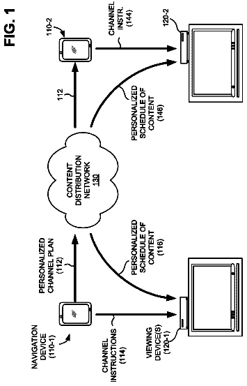
Network for personalized content aggregation platform
One or more network devices provide, to a user device, a content list of content items available for presentation.
US 9,980,013 B2 · Assignee: LG ELECTRONICS INC. · Inventors: Hwang; Soojin et al.
Sheet 1 of 18 from the published document. All sheets in the USPTO PDF
The present invention relates to a method and/or apparatus for transmitting and receiving a broadcast signal for a three-dimensional (3D) broadcasting service. A broadcast signal transmission method according to an embodiment of the present invention comprises the steps of: encoding each of packing frames, in which at least one frame among a left image frame, a right image frame, a depth map frame for the left image, and a depth map frame for the right image is packed, and signaling information for the packing frames; and generating a broadcast signal including the encoded packing frames and signaling information; and transmitting the generated broadcast signal.
Generally, a 3D image provides a stereoscopic sense using the stereoscopic visual principle of both eyes. Since human depth perception is based upon binocular parallax caused by a distance between the eyes separated by about 65 mm, the 3D image enables both right and left eyes to view respective associated plane images, thereby providing the stereoscopic sense and depth sense. A method of displaying such a 3D image may be classified into a stereoscopic scheme, a volumetric scheme, a holographic scheme, etc. In case of the stereoscopic scheme, a left view image to be viewed by the left eye and a right view image to be viewed by the right eye are provided so that the left eye views the left view image and the right eye views the right view image through polarized glasses or a display device, resulting in recognition of the 3D image effect. Advances in digital and communication technology h
1 of 18 drawing sheets so far from the published document, cropped to the drawing. Every sheet is in the USPTO PDF.
What the patent claimed, word for word. All of it is now free to use.
The present invention relates to transmission and reception of a broadcast signal. More specifically, the present invention relates to a method and/or apparatus for transmitting and receiving a broadcast signal for a 3-dimensional (3D) broadcast service.
Generally, a 3D image provides a stereoscopic sense using the stereoscopic visual principle of both eyes. Since human depth perception is based upon binocular parallax caused by a distance between the eyes separated by about 65 mm, the 3D image enables both right and left eyes to view respective associated plane images, thereby providing the stereoscopic sense and depth sense. A method of displaying such a 3D image may be classified into a stereoscopic scheme, a volumetric scheme, a holographic scheme, etc. In case of the stereoscopic scheme, a left view image to be viewed by the left eye and a right view image to be viewed by the right eye are provided so that the left eye views the left view image and the right eye views the right view image through polarized glasses or a display device, resulting in recognition of the 3D image effect.
Advances in digital and communication technology have rapidly expanded spread and demand for audio- and video-centered multimedia content in various fields such as the Internet and personal media as well as broadcast and films. Further, as a 3D television (TV) broadcast/3D film that provides the stereoscopic sense has been widely adopted, user demand for realistic media that provide sense of reality and sense of presence has increased. In addition, as display technology has developed and a TV in a household has adopted a larger screen, demand for realistic content of a high definition (HD) level or more has increased. Accordingly, in preparation for a post-HDTV market, realistic broadcast such as ultra high definition TV (UHDTV) has drawn attraction as a next-generation broadcast service along with 3DTV. In particular, discussion about an ultra high definition (UHD) broadcast service has been increasing.
Meanwhile, as a 3DTV has been widely used, spread of 3D image content through a storage medium and transmission of 3D image content through digital broadcast has been on the increase.
Furthermore, advances in production and transmission technology of a UHD image require technology for efficiently transmitting a left image, a right image, a depth map for the left image, and a depth map for the right image that constitute a 3D image. DETAILED DESCRIPTION OF THE INVENTION Technical Problems
An object of the present invention is to provide a method of efficiently transmitting 3D content using a UHD-level transmission frame.
Another object of the present invention is to provide a method of transmitting 3D content and 2D content using the same transmission frame.
Another object of the present invention is to provide a method of transmitting 3D content using a temporal scalability coding scheme. Technical Solutions
According to an aspect of the present invention, provided herein is a method of transmitting a broadcast signal, including encoding packing frames, each of which is obtained by packing at least one of a left image frame, a right image frame, a depth map frame for a left image, and a depth map frame for a right image, and signaling information about the packing frames, generating a broadcast signal including the encoded packing frames and signaling information, and transmitting the generated broadcast signal.
The encoding may include encoding a texture packing frame obtained by packing the left image frame and the right image frame and a depth map packing frame obtained by packing the depth map frame for the left image and the depth map frame for the right image, among the packing frames, to different layers.
The signaling information may includes frame packing arrangement information indicating how the packing frames are configured, the frame packing arrangement information may include information about arrangement types of the packing frames, and the arrangement types may include a type of arranging the left image and the right image in a side-by-side form in a horizontal direction in a packing frame divided into 4 regions and arranging the depth map for the left image and the depth map for the right image in a side-by-side form in a horizontal direction in a remaining region, a type of arranging the left image and the right image in a top-and-bottom form in a vertical direction in a packing frame divided into 4 regions and arranging the depth map for the left image and the depth map for the right image in a top-and-bottom form in a vertical direction in a remaining region, and a type of arranging the left image and the depth map for the left image in a vertical or horizontal direction in an odd packing frame divided into two regions and arranging the right image and the depth map for the right image in a horizontal or vertical direction in an even packing frame divided into two regions.
The frame packing arrangement information may include frame packing composition information including information about formats of the left image frame, the right image frame, the depth map frame for the left image, and the depth map frame for the right image.
The frame packing composition information may include information as to how each component in a color space for each pixel constituting the packing frames is configured.
The signaling information may include 3-dimensional (3D) operating point information indicating information about a service for transmitting the texture packing frame and depth map packing frame by different layers, and the 3D operating point information may include information for identifying whether a current service is a service for transmitting the texture packing frame and the depth map packing frame by different layers and information as to whether each layer included in a service includes the texture packing frame or the depth map packing frame.
In another aspect of the present invention, provided herein is a method of receiving a broadcast signal, including receiving a stream for packing frames, each of which is obtained by packing at least one of a left image frame, a right image frame, a depth map frame for a left image, and a depth map frame for a right image, and signaling information about the packing frames; and decoding the received stream for the packing frames using the signaling information.
A texture packing frame obtained by packing the left image frame and the right image frame and a depth map packing frame obtained by packing the depth map frame for the left image and the depth map frame for the right image, among the packing frames, may be transmitted in different layers.
The signaling information may include frame packing arrangement information indicating how the packing frames are configured, the frame packing arrangement information may include information about arrangement types of the packing frames, and the arrangement types include a type of arranging the left image and the right image in a side-by-side form in a horizontal direction in a packing frame divided into 4 regions and arranging the depth map for the left image and the depth map for the right image in a side-by-side form in a horizontal direction in a remaining region, a type of arranging the left image and the right image in a top-and-bottom form in a vertical direction in a packing frame divided into 4 regions and arranging the depth map for the left image and the depth map for the right image in a top-and-bottom form in a vertical direction in a remaining region, and a type of arranging the left image and the depth map for the left image in a vertical or horizontal direction in an odd packing frame divided into two regions and arranging the right image and the depth map for the right image in a horizontal or vertical direction in an even packing frame divided into two regions.
The frame packing arrangement information may include frame packing composition information including information about formats of the left image frame, the right image frame, the depth map frame for the left image, and the depth map frame for the right image.
The frame packing composition information may include information as to how each component in a color space for each pixel constituting the packing frames is configured.
The signaling information may include 3-dimensional (3D) operating point information indicating information about a service for transmitting the texture packing frame and depth map packing frame by different layers, and the 3D operating point information may include information for identifying whether a current service is a service for transmitting the texture packing frame and the depth map packing frame by different layers and information as to whether each layer included in a service includes the texture packing frame or the depth map packing frame.
In another aspect of the present invention, provided herein is an apparatus for transmitting a broadcast signal, including an encoder configured to encode packing frames, each of which is obtained by packing at least one of a left image frame, a right image frame, a depth map frame for a left image, and a depth map frame for a right image, and signaling information about the packing frames, a broadcast signal generator configured to generate a broadcast signal including the encoded packing frames and signaling information, and a transmitter configured to transmit the generated broadcast signal.
The encoder may encode a texture packing frame obtained by packing the left image frame and the right image frame and a depth map packing frame obtained by packing the depth map frame for the left image and the depth map frame for the right image, among the packing frames, to different layers.
In another aspect of the present invention, provided herein is an apparatus for receiving a broadcast signal, including a receiver configured to receive a stream for packing frames, each of which is obtained by packing at least one of a left image frame, a right image frame, a depth map frame for a left image, and a depth map frame for a right image, and signaling information about the packing frames, and a decoder configured to decode the received stream for the packing frames using the signaling information. Advantageous Effects
According to the present invention, 3D content can be efficiently provided using a UHD-level transmission frame.
According to the present invention, 3D content and 2D content can be transmitted using the same transmission frame.
According to the present invention, 3D content can be transmitted using a temporal scalability coding scheme.
FIG. 1 is a view illustrating a broadcast signal transmission method according to an embodiment of the present invention.
FIG. 2 is a view illustrating a frame packing arrangement method according to an embodiment of the present invention.
FIG. 3 is a diagram illustrating a method of packing a 2K left image, a 2K right image, a 2K depth map for the left image, and a 2K depth map for the right image into one 4K frame according to an embodiment (Case 1) of the present invention.
FIG. 4 is a view illustrating a method of packing a texture image (2K, 10 bits, 4:2:0) and a depth map (2K, 12 bits/2K, 15 bits) into a container (4K, 10 bits, 4:2:0) according to an embodiment (Case 1-2 and Case 1-4) of the present invention.
FIG. 5 is a view illustrating equations used to map a texture image and a depth map to a container frame in units of bits according to an embodiment (Case 1) of the present invention.
FIG. 6 is a view illustrating a method of packing a 4K left image, a 4K right image, a 4K depth map for the left image, and a 4K depth map for the right image into one 4K frame according to an embodiment (Case 2) of the present invention.
FIG. 7 is a view illustrating a method of packing a texture image (4K, 8 bits, 4:2:0/4K, 10 bits, 4:2:0) and a depth map (4K, 8 bits/2K, 12 bits) into a container (4K, 10 bits, 4:2:2/4K, 12 bits, 4:2:0) according to an embodiment (Case 2-2 and Case 2-4) of the present invention.
FIG. 8 is a view illustrating equations used to map a texture image and a depth map to a container frame in units of bits according to an embodiment (Case 2) of the present invention.
FIG. 9 is a view illustrating a method of configuring a texture image and a depth map by different HEVC temporal layers according to an embodiment (Case 3) of the present invention.
FIG. 10 is a view illustrating a method of packing a 4K left image and a 4K right image into one 4K container frame, packing a 4K depth map for the left image and a 4K depth map for the right image into another 4K container frame, and including the packed container frames in different temporal layers according to an embodiment (Case 3-1) of the present invention.
FIG. 11 is a view illustrating a method of packing a 4K left image and a 4K right image into one 4K container frame, packing a 4K depth map for the left image and a 2K depth map for the right image into another 4K container frame, and including the packed container frames in different temporal layers according to an embodiment (Case 3-2) of the present invention.
FIG. 12 is a view illustrating configuration of a frame_packing_arrangement_for_auto_stereoscopic SEI message and a frame_packing_arrangement_type_for_auto_stereoscopic field value according to an embodiment of the present invention.
FIG. 13 is a view illustrating configuration of frame_packing_composition_info( ) according to an embodiment of the present invention.
FIG. 14 is a view illustrating configuration of 3D_operating_point( ) according to an embodiment of the present invention.
FIG. 15 is a view illustrating layer_combination_type according to an embodiment of the present invention.
FIG. 16 is a view illustrating a procedure of packing a left image, a right image, a depth map for the left image, and a depth map for the right map into one container frame and transmitting the packed container frame according an embodiment (Case 1 and/or Case 2) of the present invention.
FIG. 17 is a view illustrating a procedure of transmitting a texture image and a depth map to respective layers according to an embodiment (Case 3) of the present invention.
FIG. 18 is a view illustrating a method of receiving a broadcast signal according to an embodiment of the present invention.
FIG. 19 is a view illustrating the structure of a broadcast signal transmission apparatus according to an embodiment of the present invention.
FIG. 20 is a view illustrating the structure of a broadcast signal reception apparatus according to an embodiment of the present invention.
Reference will now be made in detail to the exemplary embodiments of the present invention, examples of which are illustrated in the accompanying drawings. The present invention should not be limited to the specific embodiments described herein.
Most terms disclosed in the present invention are defined in consideration of functions of the present invention and correspond to general terms well known in the art and may vary according to intention of those skilled in the art, usual practices, or introduction of new technologies. Some of the terms mentioned in the description of the present invention may have been selected by the applicant at his or her discretion, and in such cases the detailed meanings thereof will be described in relevant parts of the description herein. Thus, the terms used in this specification should be interpreted based on the substantial meanings of the terms and the content of this specification rather than their simple names or meanings.
FIG. 1 is a view illustrating a broadcast signal transmission method according to an embodiment of the present invention.
The broadcast signal transmission method according to an embodiment of the present invention includes encoding packing frames, each of which is obtained by packing at least one of a left image frame, a right image frame, a depth map frame for a left image, and a depth map frame for a right image, and signaling information about the packing frames (SL 1010 ), generating a broadcast signal including the encoded packing frames and signaling information (SL 1020 ), and/or transmitting the generated broadcast signal (SL 1030 ). Herein, the packing frames may be referred to as transmission frames or container frames. A detailed description thereof will be given with reference to FIGS. 3, 4, 5, 6, 7, 8, and 16 .
According to another embodiment of the present invention, the encoding may include encoding a texture packing frame obtained by packing the left image frame and the right image frame and a depth map packing frame obtained by packing the depth map frame for the left image and the depth map frame for the right image, among the packing frames, to different layers. Herein, the different layers may mean different streams. In this case, a texture image may mean a left image and/or a right image. This will be described in detail with reference to FIGS. 9, 10, 11, and 17 .
According to another embodiment of the present invention, the signaling information may include frame packing arrangement information indicating how the packing frames are configured. The frame packing arrangement information may include information about arrangement types of the packing frames. The arrangement types may include a type of arranging the left image and the right image in a side-by-side form in a horizontal direction in a packing frame divided into 4 regions and arranging the depth map for the left image and the depth map for the right image in a side-by-side form in a horizontal direction in a remaining region, a type of arranging the left image and the right image in a top-and-bottom form in a vertical direction in a packing frame divided into 4 regions and arranging the depth map for the left image and the depth map for the right image in a top-and-bottom form in a vertical direction in a remaining region, and/or a type of arranging the left image and the depth map for the left image in a vertical or horizontal direction in an odd packing frame divided into two regions and arranging the right image and the depth map for the right image in a horizontal or vertical direction in an even packing frame divided into two regions. Herein, the frame packing arrangement information may indicate Frame_packing_arrangement_for_auto_stereoscopic( ). The information about arrangement types of the packing frames may indicate frame_packing_arrangement_type_for_auto_stereoscopic. The arrangement types may indicate side-by-side, top-and-bottom, and time interleaving types. A detailed description thereof will be given later with reference to FIG. 12 .
According to another embodiment of the present invention, the frame packing arrangement information may include frame packing composition information including information about formats of the left image frame, the right image frame, the depth map frame for the left image, and/or the depth map frame for the right image. The frame packing composition information may indicate frame_packing_composition_info( ). A detailed description thereof will be given later with reference to FIG. 13 .
According to another embodiment of the present invention, the frame packing composition information may include information as to how each component in a color space for each pixel constituting the packing frames is configured. Herein, the information as to how each component in a color space for each pixel constituting the packing frames is configured may indicate pixel_composition_info( ). Each component in the color space may include YCbCr. A detailed description thereof will be given later with reference to FIG. 13 .
According to another embodiment of the present invention, the signaling information may include 3D operating point information indicating information about a service for transmitting the texture packing frame and depth map packing frame by different layers and the 3D operating point information may include information for identifying whether a current service is a service for transmitting the texture packing frame and the depth map packing frame by different layers and/or information as to whether each layer included in a service includes the texture packing frame or the depth map packing frame. The 3D operating point information may indicate 3D_operating_point( ). The information for identifying whether the current service is a service for transmitting the texture packing frame and the depth map packing frame by different layers may indicate service_type. The information as to whether each layer included in a service includes the texture packing frame or the depth map packing frame may indicate layer_type. A detailed description thereof will be given later with reference to FIG. 14 .
FIG. 2 is a view illustrating a frame packing arrangement method according to an embodiment of the present invention.
According to an embodiment of the present invention, a left image, a right image, and a depth map may be transmitted in one frame having a 4K UHD format in order to provide a glasses-free 3D service. According to an embodiment of the present invention, in order to provide a glasses-free 3D service, the depth map may be transmitted in a layer for high efficiency video coding (HEVC) temporal scalability.
According to an embodiment (Case 1) of the present invention, a 2K left image, a 2K right image, a 2K depth map for the left image, and a 2K depth map for the right image may be packed into one 4K frame. In this case, downsampling is performed on the texture image and the depth map and then the downsampled texture image and depth map may be packed into the 4K frame. Herein, the texture image means an image other than the depth map and may be the left image and/or the right image. Downsampling may represent subsampling.
According to another embodiment (Case 2) of the present invention, a 4K left image, a 4K right image, a 4K depth map for the left image, and a 4K depth map for the right image may be packed into one 4K frame. Alternatively, a 4K left image, a 4K right image, a 2K depth map for the left image, and a 2K depth map for the right image may be packed into one 4K frame. In this case, the texture image may have a resolution of 4K and the depth map may be downsampled and then packed into the 4K frame.
According to another embodiment (Case 3) of the present invention, a depth map may be transmitted in a layer for HEVC temporal scalability.
While the aforementioned or later-described embodiments of the present invention describe a method of packing a texture image and/or a depth map into a 4K frame, embodiments of the present invention may be applied to packing into a frame having another resolution.
FIG. 2 illustrates a texture image format, a depth map format, and/or a container format according to case number (Case #) indicating each embodiment. The texture image format may include resolution, bit depth, and/or chroma subsampling. The depth map format may include resolution and/or bit depth. The container format may include resolution, bit depth, and/or chroma subsampling. The texture image format and/or the depth map format may indicate a source format.
Case 1-1 according to an embodiment of the present invention may indicate a method of packing a texture image having a resolution of 2K, a bit depth of 8 bits, and a chroma subsampling of 4:2:0 and a depth map having a resolution of 2K and a bit depth of 10 bits into a container frame having a resolution of 4K, a bit depth of 8 bits, and a subsampling of 4:2:0. Case 1-2 according to another embodiment of the present invention may indicate a method of packing a texture image (2K, 10 bits, 4:2:0) and a depth map (2K, 12 bits) into a container (4K, 10 bits, 4:2:0). Case 1-3 according to another embodiment of the present invention may indicate a method of packing a texture image (2K, 10 bits, 4:2:0) and a depth map (2K, 14 bits) into a container (4K, 10 bits, 4:2:0). Case 1-4 according to another embodiment of the present invention may indicate a method of packing a texture image (2K, 10 bits, 4:2:0) and a depth map (2K, 15 bits) into a container (4K, 10 bits, 4:2:0). Case 2-1 according to another embodiment of the present invention may indicate a method of packing a texture image (4K, 8 bits, 4:2:0) and a depth map (2K, 12 bits) into a container (4K, 10 bits, 4:2:0). Case 2-2 according to another embodiment of the present invention may indicate a method of packing a texture image (4K, 8 bits, 4:2:0) and a depth map (4K, 8 bits) into a container (4K, 10 bits, 4:2:2). Case 2-3 according to another embodiment of the present invention may indicate a method of packing a texture image (4K, 10 bits, 4:2:0) and a depth map (2K, 16 bit) into a container (4K, 10 bits, 4:2:2). Case 2-4 according to another embodiment of the present invention may indicate a method of packing a texture image (4K, 10 bits, 4:2:0) and a depth map (2K, 12 bits) into a container (4K, 12 bits, 4:2:0). Case 2-5 according to another embodiment of the present invention may indicate a method of packing a texture image (4K, 10 bits, 4:2:0) and a depth map (4K, 9 bits) into a container (4K, 12 bits, 4:2:2). Case 2-6 according to another embodiment of the present invention may indicate a method of packing a texture image (4K, 10 bits, 4:2:0) and a depth map (2K, 16 bits) into a container (4K, 14 bits, 4:2:0). Case 2-7 according to another embodiment of the present invention may indicate a method of packing a texture image (4K, 10 bits, 4:2:0) and a depth map (4K, 8 bits) into a container (4K, 14 bits, 4:2:2). Case 2-8 according to another embodiment of the present invention may indicate a method of packing a texture image (4K, 10 bits, 4:2:0) and a depth map (4K, 15 bits) into a container (4K, 10 bits, 4:4:4). Herein, in Cases 1-2, 1-3, and 2-7, a bit space of a container may remain. That is, even when all bits of the source format are mapped to the container format, bits that are not mapped may be present among bits constituting the container. In Case 2-3, the depth map may have a bit depth of 10, 12, 14, and/or 16 bits. In Case 2-5, the depth map may have a bit depth of 8 bits. In each of the above-described embodiments of the present invention, even when a bit depth constituting a depth map format is lower than the illustrated bit depth, the same embodiment may be applied. According to another embodiment of the present invention, even when a source format which is not illustrated in the figure is packed into a container format which is not illustrated in the figure, the above-described or later-described packing method may be applied.
FIG. 3 is a diagram illustrating a method of packing a 2K left image, a 2K right image, a 2K depth map for the left image, and a 2K depth map for the right image into one 4K frame according to an embodiment (Case 1) of the present invention.
In the figure, an embodiment is illustrated in which a 2K left image, a 2K right image, a 2K depth map for the left image, and a 2K depth map for the right image are packed into one 4K container frame in a side-by-side form. In this case, the texture images and/or the depth maps may be packed in a top-and-bottom, time interleaving, and/or rectangular region arrangement form.
Referring to FIG. 3 , the texture images may have a resolution of 3840×2160, progressive scanning, and a frame rate of 24/30/60 Hz. Herein, 3840×2160 indicates monitor resolution and has the same meaning as a resolution of 4K. 4K described in this disclosure may mean a resolution of a 4K level as well as accurately indicating a resolution of 3840×2160. 2K described in this disclosure may mean a resolution of a 2K level.
According to an embodiment of the present invention, a left image and a right image having a resolution of 4K, a depth map for the left image, and a depth map for the fight image may be downsampled to ½ width and ½ height. The downsampled texture images and depth maps have a resolution of 2K and may be packed into one 4K container frame in a side-by-side form as shown. The packed 4K container frame may be HEVC-encoded, multiplexed, and then transmitted to a receiver.
FIG. 4 is a view illustrating a method of packing a texture image (2K, 10 bits, 4:2:0) and a depth map (2K, 12 bits/2K, 15 bits) into a container (4K, 10 bits, 4:2:0) according to an embodiment (Case 1-2 and Case 1-4) of the present invention.
In this figure, a method is illustrated of mapping YCbCr of each pixel constituting the texture image and a depth value of each pixel constituting the depth map to Y′Cb′Cr′ of the container, when a container format is divided into 4 regions as in an embodiment (Case 1) of the present invention (in this case, the container format and a source texture image may have the same profile and different levels). One smallest box illustrated in FIG. 4 may represent one pixel. A number denoted together with a text in one smallest box may represent a relative pixel number. That is, in a container frame, a 0th pixel may have all of Y′, Cb′, and Cr′ but 1st, 2nd, and 3rd pixels may have only Y′ without Cb′ and Cr′.
According to an embodiment (Case 1) of the present invention, YCbCr of each pixel constituting a source texture image may be sequentially mapped to Y′Cb′Cr′ of each pixel constituting the container frame without change. An equation for this process is indicated in an upper box L 5010 of the next figure. In this equation, n denotes bit depth constituting one pixel. For example, if the texture image has a bit depth of 8 bits, n may have a value varying from 0 to 7. In addition, c_bit_depth indicates a maximum bit depth capable of being stored in the container frame, YCbCr indicates YCbCr of the texture image, and Y′Cb′Cr′ indicates YCbCr of the container frame.
According to an embodiment (Case 1) of the present invention, a depth value D(0, . . . , 3) of each pixel constituting a source depth map may be mapped first to Y′(0, . . . , 3) of each pixel constituting the container frame and the remaining bits of the depth value may be mapped to Cb′ and/or Cr′ of each pixel constituting the container frame. In this case, a bit space may remain in Y′Cb′Cr′ of each pixel constituting the container frame and the remaining bit space may be emptied. An equation for this process is indicated in a low box L 5020 of the next figure. In this equation, n denotes bit depth constituting one pixel. For example, if a texture image has a bit depth of 8 bits, n may have a value varying from 0 to 7. In addition, c_bit_depth indicates a maximum hit depth capable of being stored in the container frame, YCbCr indicates YCbCr of the texture image, Y′Cb′Cr′ indicates YCbCr of the container frame, and d_bit_depth indicates bit depth of depth map. Equation L 5020 is an equation of an embodiment different from an embodiment indicated by L 4010 and L 4020 of FIG. 4 .
The upper part L 4010 of FIG. 4 illustrates a method of mapping a texture image (2K, 10 bits, 4:2:0) and a depth map (2K 12 bits) to a container (4K, 10 bits, 4:2:0) in units of bits according to an embodiment (Case 1-2) of the present invention. In this figure, YCbCr of each pixel constituting a source texture image may be mapped to Y′Cb′Cr′ of a container frame without change. A depth value of each pixel constituting a source depth map may be mapped to Y′Cb′Cr′ of a container frame as described below. As illustrated in the upper part L 4010 , 2nd to 11th bits of D 0 may be mapped to 0th to 9th bits of Y 0 ′ and 0th and 1st bits of D 0 may be mapped to 8th and 9th bits of Cb 0 ′. 2nd to 11th bits of D 1 may be mapped to 0th to 9th bits of Y 1 ′ and 0th and 1st bits of D 1 may be mapped to 6th and 7th bits of Cb 0 ′. 2nd to 11th bits of D 2 may be mapped to 0th to 9th bits of Y 2 ′ and 0th and 1st bits of D 2 may be mapped to 8th and 9th bits of Cr 0 ′. 2nd to 11th bits of D 3 may be mapped to 0th to 9th bits of Y 3 ′ and 0th and 1st bits of D 3 may be mapped to 6th and 7th bits of Cr 0 ′.
The lower part L 4020 of FIG. 4 illustrates a method of mapping a texture image (2K, 10 bits, 4:2:0) and a depth map (2K, 15 bits) to a container (4K, 10 bits, 4:2:0) in units of bits according to an embodiment (Case 1-4) of the present invention. In this figure, YCbCr of each pixel constituting a source texture image may be mapped to Y′Cb′Cr′ of a container frame without change. A depth value of each pixel constituting a source depth map may be mapped to Y′Cb′Cr′ of a container frame as described below. As illustrated in the lower part L 4020 , 5th to 14th bits of D 0 may be mapped to 0th to 9th bits of Y 0 ′ and 0th to 4th bits of D 0 may be mapped to 5th and 9th bits of Cb 0 ′. 5th to 14th bits of D 1 may be mapped to 0th to 9th bits of Y 1 ′ and 0th to 4th bits of D 1 may be mapped to 0th to 4th bits of Cb 0 ′. 5th to 14th bits of D 2 may be mapped to 0th to 9th bits of Y 2 ′ and 0th to 4th bits of D 2 may be mapped to 5th to 9th bits of Cr 0 ′. 5th to 14th bits of D 3 may be mapped to 0th to 9th bits of Y 3 ′ and 0th to 4th bits of D 3 may be mapped to 0th to 4th bits of Cr 0 ′.
FIG. 5 is a view illustrating equations used to map a texture image and a depth map to a container frame in units of bits according to an embodiment (Case 1) of the present invention.
The equation indicated by the upper part L 5010 of the figure is used to map YCbCr of each pixel constituting a source texture image to Y′Cb′Cr′ of each pixel constituting a container frame according to an embodiment (Case 1) of the present invention. In this equation, n is bit depth constituting one pixel. For example, if the texture image has a bit depth of 8 bits, n is a variable value from 0 to 7. In addition, c_bit_depth denotes a maximum bit depth capable of being stored in the container frame, YCbCr denotes YCbCr of the texture image, and Y′Cb′Cr′ indicates YCbCr of the container frame.
The equation indicated by the lower part L 5020 of the figure is used to map a depth value D(0, . . . , 3) of each pixel constituting a source depth map to Y′Cb′Cr′ of each pixel constituting the container frame according to an embodiment (Case 1) of the present invention. In this equation, n denotes bit depth constituting one pixel. For example, if the texture image has a bit depth of 8 bits, n may be a variable value from 0 to 7. In addition, c_bit_depth denotes a maximum bit depth capable of being stored in the container frame, YCbCr denotes YCbCr of the texture image, Y′Cb′Cr′ denotes YCbCr of the container frame, and d_bit_depth denotes bit depth of the depth map.
FIG. 6 is a view illustrating a method of packing a 4K left image, a 4K right image, a 4K depth map for the left image, and a 4K depth map for the right image into one 4K frame according to an embodiment (Case 2) of the present invention.
In this figure, an embodiment is illustrated in which a 4K left image, a 4K right image, a 2K or 4K depth map for the left image, and a 2K or 4K depth map for the right image are packed into one 4K container frame in a side-by-side form. In this case, the texture images and/or the depth maps may be packed in a top-and-bottom, time interleaving, and/or rectangular region arrangement form.
Referring to FIG. 6 , the texture images may have a resolution of 3840×2160, progressive scanning, and a frame rate of 24/30/60 Hz. Herein, 3840×2160 indicates monitor resolution and has the same meaning as a resolution of 4K.
According to an embodiment of the present invention, the left image and the right image having a resolution of 4K, the depth map for the left image, and the depth map for the right image may be downsampled to a ½ width. The downsampled texture images and depth maps may still have a resolution of 4K and may be packed into one 4K container frame in a side-by-side form as shown. The packed 4K container frame may be HEVC-encoded, multiplexed, and then transmitted to a receiver. When packing is performed in the top-and-bottom form, each image and depth map may be downsampled to ½ height. In other words, a downsampling scheme of each image and depth map may differ according to a packed form.
FIG. 7 is a view illustrating a method of packing a texture image (4K, 8 bits, 4:2:0/4K, 10 bits, 4:2:0) and a depth map (4K, 8 bits/2K, 12 bits) into a container (4K, 10 bits, 4:2:2/4K, 12 bits, 4:2:0) according to an embodiment (Case 2-2 and Case 2-4) of the present invention.
In this figure, a method is illustrated of mapping YCbCr of each pixel constituting the texture image and a depth value of each pixel constituting the depth map to Y′Cb′Cr′ of the container, when a container format is divided into 2 regions (in this case, the container format and a source texture image may have the same resolution and different profiles) as in an embodiment (Case 2) of the present invention. One smallest box illustrated in FIG. 7 may represent one pixel. A number denoted together with a text in one smallest box may represent a relative pixel number. That is, in a container frame, a 0th pixel may have all of Y′, Cb′, and Cr′ but 1st, 2nd, and 3rd pixels may have only Y′ without Cb′ and Cr′.
According to an embodiment (Case 2) of the present invention, YCbCr of each pixel constituting a source texture image may be sequentially mapped to Y′Cb′Cr′ of each pixel constituting the container frame without change. An equation for this process is indicated in an upper box L 8010 of the next figure. In this equation, n denotes bit depth constituting one pixel. For example, if a texture image has a bit depth of 8 bits, n may have a value varying from it from 0 to 7. In addition, t_bit_depth indicates bit depth of the text image, YCbCr indicates YCbCr of the texture image, and Y′Cb′Cr′ indicates YCbCr of the container frame.
According to an embodiment (Case 2) of the present invention, a depth value of each pixel constituting a source depth map may be mapped to a bit space of Y′, Cb′, and Cr′ which remains after mapping Y, Cb, and Cr of each pixel constituting the texture image. That is, a depth value D(0, . . . , 3) of each pixel constituting a source depth map may be mapped first to the remaining bit space of Y′(0, . . . , 3) of each pixel constituting the container frame and the remaining bits of the depth value may be mapped to the remaining bit space of Cb′ and/or Cr′ of each pixel constituting the container frame. In this case, a bit space may remain in Y′Cb′Cr′ of each pixel constituting the container frame and the remaining bit space may be emptied.
According to an embodiment of the present invention, if a condition of Case 2 is satisfied, resolution of a source depth map is ¼ that of a container format, and chroma subsampling of the container is equal to that of the source texture image, i.e., 4:2:0, a depth value of each pixel constituting the source depth map may be mapped to Y′Cb′Cr′ of the container frame according to an equation indicated in a lower part L 8020 of the next figure. In this equation, n denotes bit depth constituting one pixel. For example, if the texture image has a bit depth of 8 bits, n may be a variable value from 0 to 7. In addition, c_bit_depth denotes a maximum bit depth capable of being stored in the container frame, YCbCr denotes YCbCr of the texture image, Y′Cb′Cr′ denotes YCbCr of the container frame, and t_bit_depth denotes bit depth of the texture image.
The description continues in the full USPTO document.
About 6,914 words. The USPTO PDF has it with every drawing.
Fees are due 3.5, 7.5 and 11.5 years after grant. This patent expired on May 22, 2026, so the fee marked "not paid" was the one that went unpaid.
METHOD AND APPARATUS FOR TRANSMITTING AND RECEIVING BROADCAST SIGNAL FOR 3D BROADCASTING SERVICE
Filed Jul 2015 · published Jun 2017Method and apparatus for transmitting and receiving broadcast signal for 3D broadcasting service
Filed Jul 2015 · granted May 2018Earlier publications, parents and continuations. None of them can still be enforced, or this patent would not be listed.
Prior art cited by the examiner or applicant. Useful when you check your own idea for novelty.
Everything on this page comes from the documents linked above.


