Cross-reference to related applications
This application is based upon and claims the benefit of priority from Japanese Patent Application No. 2015-113624, filed Jun. 4, 2015, the entire contents of which are incorporated herein by reference.
Background of the invention
1. Field of the invention
This invention relates to an imaging apparatus which performs a ranging calculation by use of a phase difference pixel output, an imaging method, and a storage medium.
2. Description of the related art
There has been known a technique to perform a ranging calculation by use of a phase difference pixel output of phase difference pixels arranged on an imaging surface, and detect a focus on the basis of the result of the ranging calculation. In the ranging calculation, ranging performance deteriorates due to the increase of a calculation error when the phase difference pixel output is smaller than a sensor output range. It is therefore necessary to ensure a predetermined phase difference pixel output.
However, in general, the phase difference pixel output is about half or less than a recording pixel output used for display or recording. Thus, various methods to ensure that the phase difference pixel output may be substantially equal to the recording pixel output have been suggested.
For example, according to Japanese Patent No. 5319347, storage control of a charge in an imaging row used for pixel generation and storage control of a charge in a focus detection row having phase difference pixels are independently performed in one frame.
According to Japanese Patent No. 5565105, additional focus detection data is calculated by performing addition processing to add at least one focus detection data to the latest focus detection data included in the latest pixel data among pixel data generated by an image pickup device.
Brief summary of the invention
In general, according to an aspect of embodiments, an imaging apparatus includes an image pickup device, a phase difference pixel extraction unit, a phase difference pixel calculation unit, a determination unit, and a ranging calculation processing unit.
The image pickup device comprises recording pixels, and phase difference pixels in which part of an opening of a light receiving portion in each of the recording pixels is blocked.
The phase difference pixel extraction unit reads phase difference pixel data obtained by performing a storing operation in the same storing time for each of the phase difference pixels in each frame of an imaging operation of the image pickup device.
The phase difference pixel calculation unit adds the read frame-by-frame phase difference pixel data of the same coordinates in a current frame and a past frame.
The determination unit determines whether to perform a focus detection operation based on the added phase difference pixel data in accordance with the characteristics of each of the phase difference pixels and the phase difference pixel data corresponding to the phase difference pixels.
The ranging calculation processing unit applies the phase difference pixel data added by the phase difference pixel calculation unit when it is determined to perform the focus detection operation on the basis of the added phase difference pixel data, and otherwise applies the phase difference pixel data in the current frame to perform the focus detection operation.
Advantages of the invention will be set forth in the description which follows, and in part will be obvious from the description, or may be learned by practice of the invention. The advantages of the invention may be realized and obtained by means of the instrumentalities and combinations particularly pointed out hereinafter.
Brief description of the several views of the drawings
The accompanying drawings, which are incorporated in and constitute a part of the specification, illustrate embodiments of the invention, and together with the general description given above and the detailed description of the embodiments given below, serve to explain the principles of the invention.
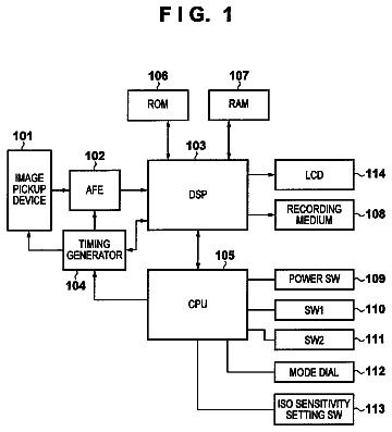
FIG. 1 is a block diagram showing one example of a functional configuration of an imaging apparatus according to a first embodiment of this invention;
FIG. 2 is a schematic diagram showing one example of pixel arrangement in an image pickup device according to the first embodiment;
FIG. 3 is a schematic diagram showing a light receiving portion seen from the front according to the first embodiment;
FIG. 4 is a block diagram showing one example of a functional configuration of a ranging calculation unit according to the first embodiment;
FIG. 5 is a block diagram showing one example of a functional configuration of a pixel data processing unit according to the first embodiment;
FIG. 6 is a schematic diagram illustrating one example of storage areas to store pixel data according to the first embodiment;
FIG. 7 is a schematic diagram illustrating one example of storage areas to store pixel data according to the first embodiment;
FIG. 8 is a flowchart showing one example of the operation of the imaging apparatus according to the first embodiment;
FIG. 9 is a timing chart showing one example of the operation of the imaging apparatus according to the first embodiment;
FIG. 10 is a schematic diagram showing one example of addition calculations according to the first embodiment;
FIG. 11 is a schematic diagram showing one example of addition calculations according to the first embodiment;
FIG. 12 is a timing chart showing one example of the operation of the imaging apparatus according to the first embodiment;
FIG. 13 is a schematic diagram showing one example of spectral characteristics of an optical filter according to the first embodiment;
FIG. 14 is a flowchart showing one example of the operation according to a second embodiment of this invention;
FIG. 15 is a schematic diagram showing the difference of output levels resulting from image heights according to the second embodiment;
FIG. 16 is a schematic diagram showing one example of a correlated calculation according to the second embodiment;
FIG. 17 is a schematic diagram showing the relation among output variations of a light source, a timing chart of a storing operation, and output scanning in a ranging area according to the second embodiment;
FIG. 18 is a schematic diagram showing one example of the change of the output level of T/B pixels in the ranging area according to the second embodiment; and
FIG. 19 is a schematic diagram showing one example of a reading method applicable to each of the embodiments of the present invention.
Detailed description of the invention
Hereinafter, each embodiment according to the present invention will be described with reference to the drawings. First Embodiment
FIG. 1 is a block diagram showing the configuration of a digital camera (hereinafter briefly referred to as a camera) as one example of an imaging apparatus according to each embodiment of the present invention. A camera 1 shown in FIG. 1 comprises a lens 11 , a lens drive unit 12 , an image pickup device 13 , an image pickup device shift unit 14 , an image pickup device drive unit 15 , a central processing unit (CPU) 16 , a memory unit 17 , a display unit 18 , a recording unit 19 , a manipulation unit 20 , a ranging calculation unit 21 , an exposure calculation unit 22 , a flicker calculation unit 23 , an image processing unit 24 , and a data/control bus 25 . The imaging apparatus 1 used in the first embodiment can be obtained by either a hardware configuration or a combinational configuration of hardware resources and software. The software of the combinational configuration is previously installed into the imaging apparatus 1 from a network or a non-transitory computer-readable storage medium Ml, as shown in FIG. 1 . For example, a program to enable the functions of the imaging apparatus 1 in the ranging calculation unit 21 is used as the software installed in this imaging apparatus 1 .
The lens 11 is an optical system to form a figure from an unshown subject into an image on a light receiving surface of the image pickup device 13 . This lens 11 has lenses such as a focus lens and a zoom lens, and a diaphragm.
The lens drive unit 12 performs, for example, the focus adjustment of the lens 11 and aperture diameter control of the diaphragm on the basis of a control signal from the CPU 16 .
The image pickup device 13 comprises two-dimensionally arranged photodiodes (hereinafter referred to as light receiving portions) that constitute pixels. The light receiving portions that constitute the image pickup device 13 generate a charge corresponding to a receiving amount of light collected by a microlens. The charge generated in the light receiving portions is stored in a capacitor connected to each of the light receiving portions. The charge stored in this capacitor is output as a pixel signal by the image pickup device drive unit 15 . The pixel signal is subjected to processing such as noise reduction processing and gain adjustment processing by an unshown imaging circuit, and then output as an image signal (hereinafter referred to as pixel data) in a digital format. Here, the image pickup device 13 preferably has an electronic shutter function. The electronic shutter function is a function to electronically control the exposure time of the image pickup device 13 on the basis of the calculation result in the exposure calculation unit 22 . As the electronic shutter, various electronic shutters such as a rolling shutter and a global shutter are applicable depending on a drive method of the image pickup device 13 that will be described later.
Color filters of Bayer arrangement are disposed in front of the light receiving portions that constitute the pixels. The Bayer arrangement has lines in which R pixels and G (Gr) pixels are alternately disposed, and lines in which G (Gb) pixels and B pixels are alternately disposed in a horizontal direction. The arrangement of the color filters is not exclusively the Bayer arrangement, and a different arrangement of other optical filters such as complementary color filters (green: G, yellow: Y, Mg: magenta, and cyan: Cy) is also suitably applicable.
Here, the image pickup device 13 in the present embodiment has, as components that enable phase difference autofocus, recording pixels (normal pixels or imaging pixels) to acquire imaging pictures for recording or display, and phase difference pixels (focus detection pixels) for focus detection. FIG. 2 is a diagram showing pixel arrangement in the image pickup device 13 in the present embodiment. As shown in FIG. 2 , phase difference pixels 1002 r, l, t , and b are discretely disposed relative to recording pixels 1001 . The phase difference pixels 1002 r, l, t , and b and the recording pixels 1001 are configured to have the same light collection efficiency of the microlens and the same distance from the microlens to the light receiving portions. The phase difference pixels 1002 r, l, t , and b are configured so that the positions of the openings of the light receiving portions are shifted as compared to those of the recording pixels 1001 or the center of the opening are shifted relative to the center of the optical axis to physically block part of the light receiving portions. The directions of light block regions of the phase difference pixels 1002 r, l, t , and b vary depending on whether the vertical lines or horizontal lines of the subject are detected. The phase difference pixels are respectively opened in a right/left (R/L) direction or a top/bottom (T/B) direction in accordance with the detection direction. In FIG. 2 , the phase difference pixel 10021 opening in the left direction and the phase difference pixel 1002 r opening in the right direction are arranged along a vertical direction (three pixels apart from each other in FIG. 2 ) on the pixels of the same color (the Gr pixels in FIG. 2 ). The phase difference pixel 1002 t opening in the top direction and the phase difference pixel 1002 b opening in the bottom direction are arranged along a horizontal direction (three pixels apart from each other in FIG. 2 ) on the pixels of the same color (the B pixels in FIG. 2 ).
As shown in FIG. 3 , the phase difference pixels are configured to be able to range regardless of whether a defocus amount is great or small. Specifically, the pixels having different opening ratios are arranged in the respective light blocking directions. FIG. 3 is a schematic diagram in which the light receiving portion is seen from the front, wherein a circular portion indicates a microlens 1003 , and a square portion indicates a light receiving region 1004 of the light receiving portion. A hatched region of the light receiving region indicates that light is blocked. Here, FIG. 3(A) shows a right opening pixel for small defocus in which the light blocking rate is low, and FIG. 3(B) shows a right opening pixel for great defocus in which the light blocking rate is high. Thus, the phase difference pixels are limited in light entrance amount so that the output level of pixel data dampens. For example, if a light blocking area ratio is 50%, the output level of phase difference pixel data (focus detection pixel data) dampens to about 1/14 to 1/20 of the output level of recording pixel data (imaging pixel data) during saturation exposure.
Although a complementary metal oxide semiconductor (CMOS) method is applied as the drive method of the image pickup device drive unit 15 in the example described in the present embodiment, not only the CMOS method but also a charge coupled device (CCD) method is suitably applicable.
The image pickup device shift unit 14 physically moves the image pickup device 13 in a plane parallel to the light receiving surface thereof and corrects, for example, a hand movement on the basis of a control signal from the CPU 16 .
The image pickup device drive unit 15 is driven on the basis of a control signal from the CPU 16 , and reads, as a pixel signal, the charge stored in the image pickup device 13 . The read pixel signal is converted into pixel data in a digital format, and sent to and stored in the memory unit 17 via the data/control bus 25 .
According to a method of reading the charge by the image pickup device drive unit 15 in the present embodiment, a storing operation is performed in the same storing time for each phase difference pixel in each frame of an imaging operation of the image pickup device 13 , and pixel data is thereby obtained.
The CPU 16 takes overall control of various sequences of the camera 1 such as driving control of the lens 11 by the lens drive unit 12 and driving control of the image pickup device 13 by the image pickup device shift unit 14 and the image pickup device drive unit 15 . The CPU 16 is interconnected with the memory unit 17 , the display unit 18 , the recording unit 19 , the manipulation unit 20 , the ranging calculation unit 21 , the exposure calculation unit 22 , the flicker calculation unit 23 , and the image processing unit 24 via the data/control bus 25 , and can send control instructions and exchange data.
The memory unit 17 is a storage medium that permits reading/writing from each unit, and acts as a working memory to transitorily store various data generated inside the camera 1 . The memory unit 17 stores, for example, pixel data read from the image pickup device 13 by the image pickup device drive unit 15 .
The display unit 18 is, for example, a liquid crystal display, and displays various images such as a still image, a moving image, and a display image based on the image data processed by the image processing unit 24 .
The recording unit 19 is, for example, a memory card which is attachable to and detachable from the camera 1 . For example, an image file including image data compressed by the image processing unit 24 is recorded in the recording unit 19 .
The manipulation unit 20 is a manipulation component such as an electric power button, a shutter button, a reproduction button, and various input keys. The manipulation unit 20 may also include a manipulation component to set a focus detection area in which a focus detection operation by the ranging calculation unit 21 is performed. If the manipulation unit 20 is manipulated by a photographer, the CPU 16 executes a sequence corresponding to this manipulation.
As shown in FIG. 4 , the ranging calculation unit 21 comprises a phase difference pixel extraction unit 211 , a pixel data processing unit 212 , a ranging calculation processing unit 213 , and a phase difference pixel frame memory 214 . The ranging calculation unit 21 has a function to read the phase difference pixel data for each frame on the basis of a control signal from the CPU 16 , and perform the focus detection operation on the basis of the phase difference pixel data for each frame. A functional configuration of the ranging calculation unit 21 will be described later.
The exposure calculation unit 22 calculates an exposure amount of the image pickup device 13 on the basis of, for example, an input from the manipulation unit 20 . The exposure calculation unit 22 sends the calculation result to the image pickup device drive unit 15 via the CPU 16 .
The flicker calculation unit 23 reads the recording pixel data stored in the memory unit 17 , and detects a flicker on the basis of this recording pixel data. If a flicker is detected, the flicker calculation unit 23 calculates control information to eliminate this flicker, and sends the calculation result to the image pickup device drive unit 15 via the CPU 16 .
The image processing unit 24 reads the recording pixel data stored in the memory unit 17 , and performs various image processing on the basis of this recording pixel data to generate image data. For example, in the case of the recording of a still image, the image processing unit 24 performs image processing for still image recording to generate still image data. Similarly, in the case of the recording of a moving image, the image processing unit 24 performs image processing for moving image recording to generate moving image data. Moreover, in the case of live-view display, the image processing unit 24 performs image processing for display to generate image data for display.
Next, the functional configuration of the ranging calculation unit 21 is described with reference to FIG. 4 . The phase difference pixel extraction unit 211 reads the phase difference pixel data which has been obtained by performing the storing operation in the same storing time for each phase difference pixel in each frame of an imaging operation. The phase difference pixel extraction unit 211 reads the phase difference pixel data in a raster order, for example, in each condition of an opening direction, thereby reading in the minimum memory size while maintaining the correspondence of coordinates between frames. Therefore, the phase difference pixel extraction unit 211 can also associate and read the phase difference pixel characteristics of the read phase difference pixel data in each frame. The phase difference pixel extraction unit 211 sends the read frame-by-frame phase difference pixel data to the pixel data processing unit 212 , and writes the data into the phase difference pixel frame memory 214 . The phase difference pixel extraction unit 211 may directly receive the pixel data read by the image pickup device drive unit 15 , and read the phase difference pixel data from the received pixel data.
The pixel data processing unit 212 comprises a determination unit 2121 and a phase difference pixel calculation unit 2122 . The pixel data processing unit 212 receives the phase difference pixel data in the current frame from the phase difference pixel extraction unit 211 in the raster order, and receives the phase difference pixel data in the corresponding past frame from the phase difference pixel frame memory 214 . The pixel data processing unit 212 processes the phase difference pixel data in the current frame and the past frame to generate phase difference pixel data to be applied to the focus detection operation, and sends the data to the ranging calculation processing unit 213 .
Having received the phase difference pixel data in the current frame in the raster order, the determination unit 2121 determines whether to perform the focus detection operation on the basis of the calculation result by the phase difference pixel calculation unit 2122 in accordance with the characteristics of each of the phase difference pixels and the phase difference pixel data corresponding to each of the phase difference pixels. The calculation here is the addition of the phase difference pixel data in the current frame and the past frame. When determining to perform the focus detection operation on the basis of the calculation result, the determination unit 2121 decides, for example, calculation information including the number of the past frames added by the phase difference pixel calculation unit 2122 . The determination unit 2121 sends the calculation information and the phase difference pixel data in the current frame to the phase difference pixel calculation unit 2122 . When determining not to perform the focus detection operation on the basis of the calculation result, the determination unit 2121 sends the phase difference pixel data in the current frame to the phase difference pixel frame memory 214 .
Having received the calculation information and the phase difference pixel data in the current frame in the raster order, the phase difference pixel calculation unit 2122 receives the corresponding phase difference pixel data in the number of the past frames for use in calculation from the phase difference pixel frame memory 214 on the basis of the number of frames in the calculation information. The phase difference pixel calculation unit 2122 adds phase difference pixel data of the same coordinates in the current frame and the past frame to the frame-by-frame phase difference pixel data read by the phase difference pixel extraction unit 211 . The phase difference pixel calculation unit 2122 sends the added phase difference pixel data to the phase difference pixel frame memory 214 .
The phase difference pixel calculation unit 2122 may have functions of subtraction, multiplication, and division, and may perform multiple kinds of calculations in accordance with the determination result by the determination unit 2121 . In this case, the calculation information generated by the determination unit 2121 further includes, for example, the presence of calculations other than the addition calculation, and an operational expression indicating the order of the execution of the calculations. For example, the calculation information in which the number of past frames is “1” and in which the operational expression is “(current frame+past frames)/2” indicates the additional average of the current frame and one past frame. The function of multiplication is used, for example, for a gain increase in the phase difference pixel data. The function of subtraction is used, for example, to estimate the degree of movement of the subject between frames by evaluating an output difference between the frames.
A specific configuration in the pixel data processing unit 212 may comprise selectors (SEL) 2123 , 2125 , and 2127 , an addition/subtraction processing unit 2124 , and a multiplication/division processing unit 2126 , as shown in FIG. 5 . Here, each of the SEL 2123 , 2125 , and 2127 may comprise a function equivalent to that of the determination unit 2121 described above, and the addition/subtraction processing unit 2124 and the multiplication/division processing unit 2126 may comprise a function equivalent to that of the phase difference pixel calculation unit 2122 described above. For example, when receiving each phase difference pixel data from the phase difference pixel extraction unit 211 , the SEL 2123 determines whether to perform the addition calculation and/or the subtraction calculation. When determining to perform the addition calculation and/or the subtraction calculation, the SEL 2123 sends the phase difference pixel data to the addition/subtraction processing unit 2124 . Otherwise, the SEL 2123 sends the phase difference pixel data to the SEL 2125 . When receiving the phase difference pixel data from the SEL 2123 , the addition/subtraction processing unit 2124 reads the phase difference pixel data of the same coordinates in the past frame, and performs the addition calculation and/or the subtraction calculation. The addition/subtraction processing unit 2124 sends the calculated phase difference pixel data to the SEL 2125 . When receiving the phase difference pixel data, the SEL 2125 determines whether to perform the multiplication calculation and/or the division calculation. The SEL 2125 sends, to the multiplication/division processing unit 2126 , the phase difference pixel data for which it has been determined to perform the multiplication calculation and/or the division calculation. Otherwise, the SEL 2125 sends the phase difference pixel data to the SEL 2127 . When receiving the phase difference pixel data from the SEL 2125 , the multiplication/division processing unit 2126 reads the phase difference pixel data of the same coordinates in the past frame, and performs the multiplication calculation and/or the division calculation. The multiplication/division processing unit 2126 sends the calculated phase difference pixel data to the SEL 2127 . Having received the phase difference pixel data, the SEL 2127 determines whether to perform the focus detection operation on the basis of the phase difference pixel data. When determining to perform the focus detection operation, the SEL 2127 sends the phase difference pixel data to the phase difference pixel frame memory 214 .
Here, the explanation returns to FIG. 4 . When the determination and calculation by the pixel data processing unit 212 are finished, the ranging calculation processing unit 213 reads the processed phase difference pixel data written in the phase difference pixel frame memory 214 from the pixel data processing unit 212 . When the determination unit 2121 determines to perform the focus detection operation on the basis of the added phase difference pixel data, the ranging calculation processing unit 213 applies the phase difference pixel data added by the phase difference pixel calculation unit 2122 , and performs the focus detection operation. When the determination unit 2121 determines not to perform the focus detection operation on the basis of the added phase difference pixel data, the ranging calculation processing unit 213 applies the phase difference pixel data in the current frame, and then performs the focus detection operation. The ranging calculation processing unit 213 sends the execution result of the focus detection operation to the CPU 16 .
Here, the ranging calculation processing in the present embodiment is performed by detecting a phase difference made between a pair of pixel data by the R/L opening pixels and the T/B opening pixels. However, as the detected phase difference, not only the phase difference between a pair of pixels but also the average value of the phase differences between pairs of pixels in a predetermined range in a ranging area is used in the case of both R/L and T/B.
The phase difference pixel frame memory 214 is a memory that permits reading/writing from each of the units 211 , 212 , and 213 , and comprises an R opening pixel holding unit 2141 , an L opening pixel holding unit 2142 , a T opening pixel holding unit 2143 , and a B opening pixel holding unit 2144 . Each of the opening pixel holding units 2141 to 2144 stores the phase difference pixel data classified and read by the phase difference pixel extraction unit 211 in the raster order for each condition such as an opening direction so that the phase difference pixel data are associated by coordinate information and a frame unit. That is, the R opening pixel holding unit 2141 stores the phase difference pixel data for right opening pixels, the L opening pixel holding unit 2142 stores the phase difference pixel data for left opening pixels, the T opening pixel holding unit 2143 stores the phase difference pixel data for top opening pixels, and the B opening pixel holding unit 2144 stores the phase difference pixel data for bottom opening pixels. Each of the opening pixel holding units 2141 to 2144 may store the phase difference pixel data further classified by the phase difference pixel extraction unit 211 in accordance with other phase difference pixel characteristics such as the difference of the light blocking rates. The phase difference pixel frame memory 214 reads the phase difference pixel data in the past frame at the request of the phase difference pixel calculation unit 2122 , and sends the phase difference pixel data to the phase difference pixel calculation unit 2122 . The phase difference pixel frame memory 214 stores the processed phase difference pixel data sent from the pixel data processing unit 212 , and sends the phase difference pixel data to the ranging calculation processing unit 213 at the request of the ranging calculation processing unit 213 . The phase difference pixel frame memory 214 is not exclusively provided in the ranging calculation unit 21 , and may be additionally provided in the memory unit 17 .
Here, an example of storage areas in a memory to store the read pixel data in the present embodiment is shown in FIG. 6 and FIG. 7 . In the example of FIG. 6 , triggered by a horizontal synchronization signal 2011 , pixel data in a certain frame are read from the image pickup device 13 row by row and sequentially written into the storage area in order from pixel data in the pixel located in the first row regardless of the recording pixels and the phase difference pixels. Triggered by a vertical synchronization signal 2012 , pixel data in the next frame are read from the image pickup device 13 row by row and written into the storage area in order from the first row again. In FIG. 6 , a storage area 2013 indicates an area to which coordinates corresponding to the rows and columns of the pixel arrangement are allocated. Here, numbers indicated on the left end and upper end of the storage area 2013 correspond to row numbers and column numbers of the pixel arrangement, respectively. Blank storage areas 2013 a in the storage area 2013 indicate storage areas for the recording pixel data. Storage areas 2013 b with characters such as L, R, T, and B indicate storage areas for the phase difference pixel data that are open in the left, right, top, and bottom directions, respectively. In the storage area 2013 , storage of the pixel data in one frame is triggered by the vertical synchronization signal 2012 , and row-by-row storage of the pixel data is triggered by the horizontal synchronization signal 2011 . The phase difference pixel data may be further associated with phase difference pixel characteristics such as the left, right, top, and bottom (L, R, T, and B) directions in which the respective phase difference pixels are blocked from light, the light blocking rates, and the kinds of optical filters, and stored in the storage areas 2013 b accordingly.
In the example shown in FIG. 7 , the recording pixel data and the phase difference pixel data are separately stored in storage areas 2014 and 2015 . In the example of FIG. 7 , pixel data in a certain frame are read from pixel data in the recording pixels alone in the first half of a horizontal period, and sequentially written into the storage areas. Moreover, in the example of FIG. 7 , pixel data in a certain frame are read from pixel data in the phase difference pixels alone in the second half of the horizontal period, and sequentially written into the storage areas. In FIG. 7 , storage areas 2014 a indicate areas to store the recording pixel data as in FIG. 6 . In contrast, storage areas 2014 b do not indicate areas to store the phase difference pixel data but indicate areas to store, as the recording pixel data, a value X(n) interpolated by the recording pixel data for the surrounding adjacent pixels of the same color. The phase difference pixel data are transitorily held, for example, in a line memory provided in the image pickup device 13 in the first half of the horizontal period. The phase difference pixel data held in the line memory are read after the recording pixel data in the same row are stored in the storage area 2014 , and the phase difference pixel data held are stored in storage areas 2015 b . Dummy data D are stored in storage areas 2015 a other than the areas to store the phase difference pixel data. In any case, the pixel data read in the present embodiment are stored in association with the coordinates of the pixel arrangement. The coordinates of the pixel arrangement are also associated with phase difference pixel characteristics such as light blocking directions of the phase difference pixel data, the light blocking rates, and the kinds of optical filters, and stored accordingly.
Next, a specific operation of the above imaging apparatus according to the present embodiment is described. FIG. 8 is a flowchart showing the processes of the focus detection operation by the imaging apparatus. Each of the processes in FIG. 8 is mainly performed by the ranging calculation unit 21 and the image processing unit 24 . FIG. 8 is started, for example, when the shutter button of the manipulation unit 20 is half-pressed in a still image photography mode, but may be started at the time of moving image photography or at the time of live-view. In accordance with each of the processes in FIG. 8 , the camera 1 acts along a timing chart shown in FIG. 9 by way of example. That is, in the following explanation, the camera 1 drives the image pickup device drive unit 15 in accordance with the CMOS sensor method, and reads pixel data from a charge stored in the image pickup device 13 by rolling reading.
First of all, the CPU 16 sends a vertical synchronization signal shown in FIG. 9(A) and a horizontal synchronization signal shown in FIG. 9(B) to the image pickup device drive unit 15 .
The image pickup device drive unit 15 then stores a charge in the image pickup device 13 , and performs an output scan of the pixel data, as shown in FIG. 9(C) . Specifically, the image pickup device drive unit 15 controls the electronic shutter from a time T 0 . Under this control, the light receiving portions of the image pickup device 13 are exposed for a given time row by row at staggered times in order from the top pixels to bottom pixels arranged on the image pickup device 13 . The image pickup device drive unit 15 starts the output of the pixel data at a time T 1 after the end of exposure. Here, in FIG. 9 , the phase difference pixels are arranged in ranges other than the upper and lower ends of the light receiving surfaces among the ranges in which the recording pixels are arranged. Therefore, recording pixel data F 1 is output in a period from the time T 1 to a time T 4 as shown in FIG. 9(D) , and phase difference pixel data Z 1 is output in a period from a time T 2 to a time T 3 as shown in FIG. 9(E) . The camera 1 repeats a series of such operations from the time T 0 to the time T 4 frame by frame, and sequentially outputs recording pixel data Fn and phase difference pixel data Zn in a frame number n.
The phase difference pixel extraction unit 211 reads the phase difference pixel data which has been obtained by performing the storing operation in the same storing time for each phase difference pixel in each frame of the imaging operation of the image pickup device 13 (ST 110 ). In FIG. 9 , the phase difference pixel extraction unit 211 reads the phase difference pixel data Z 1 output in the frame number “1”, stores the phase difference pixel data Z 1 in the phase difference pixel frame memory 214 , and sends the phase difference pixel data Z 1 to the pixel data processing unit 212 . In this instance, at least phase difference pixel data Z 0 in the frame number “0” is stored in the phase difference pixel frame memory 214 as pixel data in the past frame.
Depending on the characteristics of each phase difference pixel and the phase difference pixel data corresponding to each phase difference pixel, the determination unit 2121 determines whether to perform the focus detection operation on the basis of the added phase difference pixel data (ST 120 ).
Specifically, when determining to perform the focus detection operation on the basis of the added phase difference pixel data (ST 120 ; yes), the determination unit 2121 sends the phase difference pixel data Z 1 in the current frame to the phase difference pixel calculation unit 2122 . The phase difference pixel calculation unit 2122 receives the phase difference pixel data in the past frame from the phase difference pixel frame memory 214 , and adds the phase difference pixel data of the same coordinates between the respective frames (ST 130 ). The phase difference pixel calculation unit 2122 sends the added phase difference pixel data to the phase difference pixel frame memory 214 . In contrast, when determining not to perform the focus detection operation on the basis of the added phase difference pixel data (ST 120 ; no), the determination unit 2121 sends the phase difference pixel data in the current frame to the phase difference pixel frame memory 214 . The pixel data processing unit 212 repeats steps ST 120 to ST 130 until steps ST 120 to ST 130 are performed for all the phase difference pixels (ST 140 ).
The example of FIG. 9 assumes that the determination unit 2121 determines that all the phase difference pixel data are added. Therefore, the phase difference pixel calculation unit 2122 adds the phase difference pixel data Z 1 to the phase difference pixel data Z 0 in the previous frame to generate phase difference pixel data S 1 as shown in FIG. 9(F) .
Here, in the example of the addition calculation shown in FIG. 9 , the addition calculation is performed regarding the pixel data for the phase difference pixels located at the same coordinates as shown in FIG. 10 , in the case of the pixel arrangement in the image pickup device 13 . Here, numerical values of the phase difference pixel data in each of pixel arrangements 2016 to 2018 indicate values of the frame number “0”, the frame number “1”, and the addition of the frame number “0” and the frame number “1”, respectively. Blank areas on each of the pixel arrangements 2016 to 2018 indicate recording pixels, and areas with numerical values indicate the phase difference pixels from which the phase difference pixel data of these numerical values are output. At the time of the actual addition calculation, the phase difference pixel extraction unit 211 reads the phase difference pixel data alone from the storage areas in the raster order or in the order in which the phase difference pixel data are rearranged in a predetermined order such as an opening direction order, as shown in FIG. 11 . Here, numerical values in each of pixel arrangements 2019 to 2021 indicate values of the frame number “0”, the frame number “1”, and the addition of the frame number “0” and the frame number “1”, respectively. The read phase difference pixel data are also associated with phase difference pixel characteristics such as light blocking directions, the light blocking rates, and the kinds of optical filters as necessary. Therefore, the phase difference pixel calculation unit 2122 can perform a calculation between frames in the minimum memory area while maintaining the association with phase difference pixel characteristics such as predetermined coordinate arrangement of the phase difference pixels, the opening directions, the light blocking rates, and the kinds of optical filters.
The description continues in the full USPTO document.
 Lapsed, fee not paid4 drawings