Cross-reference to related application
This application is the U.S. national phase of the International Patent Application No. PCT/JP2013/081242 filed Nov. 20, 2013, the entire content of which is incorporated herein by reference.
Field
The present disclosure relates to a game machine, a dice game system, and a display program which are used at casinos.
Background
Games are played at casinos at various places in the world by dealers playing dice and trumps and operating lottery machines such as roulettes and by players predicting pips on dice, combinations of trumps, and winning pockets in roulettes, bidding, for example, chips on a betting board, and earning dividends according to the lottery results.
With the advances in electronics and communications technology in recent years, game machine systems in which computer devices serve in place of the dealers and perform the lottery operation conventionally performed by the dealers have been being marketed.
For example, Japanese Patent Application Laid-Open (Kokai) Publication No. 2009-189802, Japanese Patent Application Laid-Open (Kokai) Publication No. 2009-189803, and Japanese Patent Application Laid-Open (Kokai) Publication No. 2012-165920 disclose game devices configured so that they can play SICBO, which is a popular dice game at casinos in Asian locations such as Macao (PTL 1 to PTL 3). SICBO originally is a game in which a dealer throws three dice and a player predicts the total number of pips appearing on the dice and a combination of the pips, bets on patterns and numbers on a betting table (by betting chips or the like on the predicted content), and earns dividends according to the number of pips on the dice. The betting table is provided with, for example, an area for making bets by predicting the number of pips appearing on the dice (for example, a combination of two dice from among the three dice [Combination]), an area for making bets by predicting the total number on the dice (for example, the total number on the three dice [Total]), and further an area for making bets by predicting whether the total number of pips on the three dice is “Big” or “Small” (for example, “Big” (11 to 17) or “Small” (4 to 10) [Big or Small]). The dealer throws the three dice and the player makes a bet while the dealer covers the dice with a cover; and after the dealer declares betting closed (for example, by declaring “No more bet”), the dealer opens the cover and reveals the pips on each dice, thereby determining a win or loss.
The game devices described in PTL 1 and PTL 2 mentioned above are configured so that a plurality of stations 4 are placed at a housing 2 formed so as to surround a game unit 3, in which dice 7 are operated, and each of a plurality of players is seated at each station 4 and can play the SICBO game. Each station 4 is designed so that images of the betting board are displayed on an image display device 7 with a touch panel attached to its front face and the player can perform betting operations as in conventional cases by operating the touch panel (PTL 1: FIG. 2 and FIG. 6; and PTL 2: FIG. 2 and FIG. 6).
A game machine described in PTL 3 is designed so that the stations 4 are placed so as to surround a SICBO device 3 where dice 27 are operated; and each station 4 accepts bets as the player performs touch operations on a touch panel 56 attached to a front face of a display 8 (PTL 3: FIG. 1, FIG. 3, and FIG. 6).
Meanwhile, the above-mentioned PTL 1 to PTL 3 do not clearly describe whether to display a betting table on which the player's own betting status is reflected, or display a betting table on which the betting status of other stations is also included and reflected, on the display for each station.
When only the player's own betting status is displayed at each station, it is very obvious the betting amount the player themselves has bet on which betting position; however, that player cannot tell betting positions and betting amounts at other stations.
Since the amount of dividends at a specific betting position changes according to how much other stations are betting on that specific betting position, the player needs to know the betting status of other stations in order to predict the expected amount of dividends at the specific betting position.
On the other hand, when the betting status of all the stations including other stations is displayed, the betting status is displayed in the same manner as the conventional game in which a plurality of players make bets on one betting board at the same time, so that it is easy to comprehend the entire betting status, but it is difficult for the player to comprehend the betting amount the player themselves has bet on which betting position.
Particularly, with a system of a huge game machine in which lottery results of one lottery apparatus are shared by many stations, as the number of bets from each station becomes larger in the middle and last half of a betting period, it becomes impossible to comprehend the player's own betting status.
So, an object of the present disclosure is to provide a game environment where the operation status of the player's own station machine can be easily monitored and operated and the operation status of other station machines can be also easily monitored.
Summary
A game machine according to an embodiment which solves the above-described problems is a game machine capable of executing a specified game by connecting a plurality of station machines to enable communications between them, each of the station machines including a display panel that displays an image indicating progress of the game including a player's own operation status; and the station machine being configured to: generate a first display image including the player's own operation status; generate a second display image including the player's own operation status and an operation status of other station machines; and switch between a first display mode to display the first display image on the display panel and a second display mode to display the second display image on the display panel.
A game machine according to an embodiment which solves the above-described problems is a game machine comprising: a plurality of station machines; and a master machine connected to the plurality of station machines to enable communications between them, each of the station machines comprising: a touch panel that accepts operation by a player; a display panel that displays an image indicating progress of a game including the player's own operation status corresponding to the operation over the touch panel; and a control unit that transmits the player's own operation status to the master machine and controls display on the display panel; the master machine integrating the operation status at each station machine to form an integrated operation status and transmitting the integrated operation status to each station machine; and the station machine being configured to: generate a first display image including the player's own operation status; generate a second display image including the player's own operation status and an operation status of other station machines by referring to the transmitted integrated operation status; and switch between a first display mode to display the first display image on the display panel and a second display mode to display a synthetic image, which is obtained by synthesizing the first display image with the second display image, on the display panel.
A dice game system according to an embodiment which solves the above-described problems is a dice game system comprising: a plurality of station machines; a master machine connected to the plurality of station machines to enable communications between them; and a dice lottery apparatus that performs lottery using dice, each of the station machines comprising: a touch panel that accepts operation by a player; a display panel that displays an image indicating progress of a game including the player's own operation status corresponding to the operation over the touch panel; a control unit that transmits the player's own operation status to the master machine and controls display on the display panel; and a display switching switch provided outside the touch panel; the master machine: integrating the operation status at each station machine to form integrated operation information and transmitting the integrated operation information to each station machine; and transmitting dividend information according to a result of the lottery at the dice lottery apparatus to each station machine; and wherein the control unit for the station machine: generates a first display image indicating, on a first betting board, a pip-count prediction status at the player's own station machine including the player's own operation status; generates a second display image indicating, on a second betting board, a pip-count prediction status of all the plurality of station machines by referring to the transmitted integrated operation information; displays the first display image in response to first operation of the display switching switch; displays a synthetic image which is obtained by synthesizing the first display image with the second display image in response to second operation of the display switching switch; and displays a dividend image corresponding to the pip-count prediction status of each station machine by referring to the transmitted dividend information.
A display program according to an embodiment which solves the above-described problems is a display program executed by a plurality of station machines in a game system capable of executing a specified game by connecting the plurality of station machines to enable communications between them, each of the station machines comprising: a touch panel that accepts operation by a player; a display panel that displays an image indicating progress of the game including the player's own operation status corresponding to the operation over the touch panel; and a control unit that controls display on the display panel; and the station machine being configured to enable the control unit execute: a function that accepts operation performed on the touch panel; a function that generates a first display image including the player's own operation status based on the operation performed on the touch panel; a function that generates a second display image including the player's own operation status and an operation status of other station machines; a function that displays the first display image on the display panel in response to first operation of a display switching switch; and a function that displays, on the display panel, an image obtained by synthesizing the first display image with the second display image in response to second operation of the display switching switch.
An embodiment may include the following configurations when desirable.
In the second display mode, the station machine accepts operation performed on the touch panel in response to the first display image and/or operation performed on the touch panel in response to the second display image.
The station machine is equipped with a display switching switch for switching between the first display mode and the second display mode outside the touch panel.
The second display image comprises an additional image according to a total expected number of pips on the dice corresponding to areas constituting the second betting board.
An embodiment is configured so that it is possible to switch between the first display mode to display the first display image including the player's own operation status and the second display mode to display the synthetic image obtained by synthesizing the first display image with the second display image to display the second display image including the player's own operation status and the operation status of other station machines. Therefore, it is easy to monitor and operate the operation status of the player's own station machine and also monitor the operation status of other station machines.
Brief description of drawings
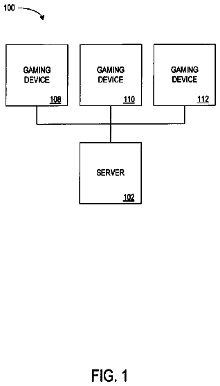
FIG. 1 is a schematic configuration diagram illustrating one embodiment of a dice game system according to an embodiment;
FIG. 2 is an external front view of a dice lottery apparatus according to the embodiment;
FIG. 3 is a system block diagram of the dice lottery apparatus according to the embodiment;
FIG. 4 is a diagram illustrating a schematic configuration of dice blowers according to the embodiment;
FIG. 5 is a flowchart illustrating dice lottery processing according to the embodiment;
FIG. 6 is a system block diagram of a master machine according to the embodiment;
FIG. 7 is a diagram illustrating an example of a display image of a live screen according to the embodiment;
FIG. 8 is a perspective view for explaining an external configuration of the station machine according to the embodiment;
FIG. 9 is a perspective view for explaining an internal configuration of a station machine according to the embodiment;
FIG. 10 is a system block diagram of the station machine according to the embodiment;
FIG. 11 is a diagram illustrating an example of a first display image in a first display mode;
FIG. 12 is a diagram illustrating an example of a display image of a betting board;
FIG. 13 is a diagram illustrating an example of a display image before betting operation in a second display mode;
FIG. 14 is a diagram illustrating an example of a display image when the betting operation proceeds in the second display mode;
FIG. 15 is a diagram illustrating an example of procedure
for chip movement operation in the second display mode;
FIG. 16 is a diagram illustrating an example of procedure
for the chip movement operation in the second display mode;
FIG. 17 is a diagram illustrating an example of procedure
for the chip movement operation in the second display mode;
FIG. 18 is a diagram illustrating a case where one chip movement operation in the second display mode has been completed;
FIG. 19 is a diagram for illustratively explaining instant betting operation;
FIG. 20 is a diagram for illustratively explaining overlaying operation;
FIG. 21 is an example of a flowchart explaining operation of the master machine according to the embodiment; and
FIG. 22 is an example of a flowchart explaining operation of the station machine according to the embodiment.
Detailed description
Embodiments will be explained below in detail. Incidentally, the following embodiments are just for illustration and are not intended to be limited to such embodiments. Moreover, embodiments can vary in different ways as long as such variations do not depart from the gist of the disclosure. Furthermore, a person skilled in the art can adopt an embodiment in which each element described below is replaced with its equivalent.
Furthermore, a positional relationship indicating, for example, whether the relevant position is above or below something or on the right or left side of something as indicated whenever necessary is based on illustrations of the drawings unless otherwise specified. Furthermore, various sizes and proportions in the drawings are not limited to the proportions indicated in the drawings. Also, in the interest of ease of comprehension, the following explanation will be given by taking an example of an embodiment implemented by using an information processing device for games; however, the scope is not limited to such embodiment as described above.
Definitions
Terms are defined as follows in this description.
“Chips”: virtual coins used by players to declare their pip-count prediction. One “chip” has a certain amount of credits or points.
A “betting board”: a virtual table where the chips are placed in order for the players to declare their pip-count prediction. The betting board is prepared according to the type of game.
“Bet/betting”: to declare the player's pip-count prediction. Specifically speaking, “bet/betting” means to place the chips on the betting board.
A “betting position”: a position at which to place the chips on the betting board. Different betting positions are set according to the types of games.
A “betting amount”: a total number of credits or points of the chips placed at the same betting position. The betting amount means a subtotal of bets placed at the same betting position by the same player or a total number of bets placed at the same betting position by all the players.
A “betting status”: an integrated operation status which is obtained by integrating the betting status of each player or each group of players and which indicates how much is being bet at which betting position on the betting board.
“Synthesis”: to combine two display images and display them on one display panel. Synthesis comprises changing of the size, shape, or position of either one or both of the two display images so that both display images can be visually recognized. Moreover, synthesis comprises overlapping either one of the two display images over the other or displaying them in individual windows. A. Configuration
An embodiment relates to a dice game system configured to be capable of executing SICBO.
A-1. Dice Game System
FIG. 1 is a schematic configuration diagram illustrating an embodiment of a dice game system. Referring to FIG. 1 , a dice game system 1000 according to this embodiment comprises a dice lottery apparatus 100 , respective station machines 200 -N (hereinafter simply referred to as the “station machine 200 ” when it is unnecessary to specify each station machine), and a master machine 300 . The dice lottery apparatus 100 , the respective station machines 200 -N, and the master machine 300 are connected via wire and/or wirelessly to each other via a network 400 such as a LAN (Local Area Network), a WAN (Wide Area Network), or the Internet so as to enable communications between them. The network 400 may be either a wireless LAN or a wired LAN, or a combination of the wireless LAN and the wired LAN; and a wireless LAN device or a wired LAN device may be mounted in each of the above-mentioned equipment units or may be connected as an external device like a LAN card.
The dice lottery apparatus 100 is a lottery means for performing dice lottery in accordance with SICBO game rules, using three dice. Each station machine 200 -N is an operation display console at which each player is seated to execute betting processing according to the predicted number of pips on the dice. The master machine 300 is a server apparatus configured to be capable of controlling dice lottery at the dice lottery apparatus 100 , receiving the betting status and other operation information of each station machine 200 -N in a manner capable of updating the above-mentioned information, and delivering the integrated operation status obtained by integrating the above-mentioned information.
Incidentally, depending on the content of the game system, the game system can be configured by omitting the dice lottery apparatus 100 and/or the master machine 300 and connecting only the plurality of station machines 200 to each other.
A-2. Dice Lottery Apparatus
FIG. 2 illustrates an external front view of the dice lottery apparatus 100 and FIG. 3 illustrates a system block diagram of the dice lottery apparatus 100 .
Referring to FIG. 2 , the dice lottery apparatus 100 comprises, as its main structural elements, a dice blower 110 and a monitor 331 placed above the dice blower 110 . The configuration of the dice blower 110 will be described later. The monitor 331 is a display means for receiving an image signal from a master display device 330 of the master machine 300 described later and displaying a live screen LS.
Referring to FIG. 3 , the dice lottery apparatus 100 comprises, as mechanical functional blocks, the dice blower 110 , a pip-count detector 120 , and a dice leaning prevention device 130 and comprises, as electrical functional blocks, a control unit 150 , a sound control unit 160 , and a communication control unit 170 .
FIG. 4 is a diagram illustrating a schematic configuration of the dice blower 110 . The dice blower 110 is constituted by three dice blowers 110 a to 110 c as illustrated in FIG. 4 . Each dice blower 110 a to 110 c comprises a blowing mechanism 112 , a dice table 114 mounted above the blowing mechanism 112 , and a blowing pipe 111 mounted above the dice table 114 .
The blowing pipe 111 is formed of a transparent material such as acryl and is designed so that an audience around each player can observe the process from operation to blow air upward to lift a dice D to operation to stop the dice. The dice D which is a light-weight, rounded dice formed of, for example, plastic is placed inside the blowing pipe 111 so that the dice D can be lifted with the air blown upward above the dice table 114 .
The blowing mechanism 112 has an upward-blowing opening towards the dice table 114 and the blowing pipe 111 . The blowing mechanism 112 comprises an air intake, a shutter for opening or closing the air intake, and fans for introducing air through the air intake (although they are not shown in the drawing); and the blowing mechanism 12 can send the air towards the dice D placed on the dice table 114 , blow air upward to lift the dice D, and rotate the dice D in a blown-and-lifted state inside the blowing pipe 111 . When the air sent by the blowing mechanism 112 stops, the dice D which has lost the drifting air flow falls down to the dice table 114 , repeatedly bounces on the dice table 114 because of its own elasticity, and then gradually stops moving.
Referring back to FIG. 3 , the pip-count detector 120 comprises an image sensor 121 such as an infrared camera or a CCD (Charge Coupled Device) sensor. When the movement of the dice D lifted with the air blown by the blowing mechanism 112 stops and the number of pips on the dice is determined, the pip-count detector 120 captures an image of the number of pips on the dice placed on the dice table 114 and transmits the captured image data of the dice D (hereinafter referred to as the “dice image data”) to the master machine 300 .
The dice leaning prevention device 130 comprises a vibrating device 131 which is a combination of a stepping motor or the like and a pulley and is configured so that it can shake the dice table 114 . The dice leaning prevention device 130 prevents the fallen dice D from leaning against an inside wall of the blowing pipe 111 and making it difficult to identify the number of pips on the dice.
The control unit 150 is a computer device composed of, for example, a CPU, a ROM, and a RAM and is designed to: control the dice blower 110 in accordance with a dice tossing instruction, a lottery start instruction (lottery instruction), and so on transmitted from the master machine 300 via the network 400 to perform, for example, dice lottery; and control the pip-count detector 120 to transmit the dice image data to the master machine 300 once the number of pips on the dice is determined. The sound control unit 160 is configured so that it can output sounds to boost the progress of a game in synchronization with, for example, tossing of the dice. The communication control unit 170 is a communication device to perform data communications between the master machine 300 and the dice lottery apparatus 100 .
FIG. 5 shows a flowchart illustrating dice lottery processing executed by the dice lottery apparatus 100 . Referring to FIG. 5 , when the control unit 150 for the dice lottery apparatus 100 receives an instruction to toss the dice D from the master machine 300 via the network 400 (step T 1 : YES), it starts the operation of the dice blower 110 to blow air upward to lift the dice D in order to toss the dice D (step T 2 ). The dice blower 110 controls the blowing mechanism 112 , opens the shutter of the air intake, activates the fans, and starts sending the air towards the dice D which stays still on the dice table 114 . The dice D which has received the air flow rotates and is lifted with the air blown upward by a levitation force inside the blowing pipe 111 . When the dice D rises to a certain height within the blowing pipe 111 , the levitation force from the air flow which causes upward-blowing balances with the gravity force acting on the dice D and the dice D keeps floating at almost the same height. Next, when the control unit 150 for the dice lottery apparatus 100 receives a dice lottery instruction (that is, the dice D tossing stop instruction) from the master machine 300 via the network 400 (step T 3 : YES), the control unit 150 stops the upward-blowing operation by the dice blower 110 in order to make the dice D fall down and determine the number of pips on the dice. The dice blower 110 closes the shutter and shuts off the power of the fans in order to block the air flowing into the fans. As a result, the air flow inside the blowing pipe 111 is completely blocked and the floating dice D immediately falls down towards the dice table 114 within the blowing pipe 111 . When this happens, the control unit 150 for the dice lottery apparatus 100 controls the dice leaning prevention device 130 to prevent the dice D from entering a state of leaning against the inside surface of the blowing pipe 111 (step T 4 ). The dice leaning prevention device 130 controls the vibrating device 131 to slightly vibrate the dice table 114 on which the dice D is placed. Accordingly, the dice D becomes static in a horizontal state on the dice table 114 without leaning against the inside surface of the blowing pipe 111 and the number of pips on the dice D is determined.
Moreover, the control unit 150 controls the pip-count detector 120 to have the image sensor 121 start capturing images of the number of pips on the dice D. The dice image data captured by the pip-count detector 120 are transmitted sequentially from the communication control unit (communication control unit) 170 for the dice lottery apparatus 100 to the master machine 300 via the network 400 (step T 5 ).
A-3. Master Machine
FIG. 6 illustrates a system block diagram of the master machine 300 . Referring to FIG. 6 , the master machine 300 comprises a main control unit 310 , a communication control unit 320 , a master display device 330 , and a timer 340 .
The main control unit 310 serves a function centrally controlling the master machine 300 and comprises, for example, a CPU 311 , a ROM 312 , and a RAM 313 . The main control unit 310 is connected, via a bus 350 , to the communication control unit 320 , the master display device 330 , the timer 340 , and so on.
The ROM 312 records an IPL (Initial Program Loader) to be executed at first when executing game processing. Moreover, the ROM 312 records, for example, an operating system program that is required to control the operation of the entire master machine 300 .
The RAM 313 is a temporary storage device equipped with a sufficient memory space for the CPU 311 to execute software programs and temporarily store other data. The RAM 313 stores programs which have been read for the master machine, necessary data for communications between the respective stations 200 and for communications with the dice lottery apparatus 100 , the dice image data received from the dice lottery apparatus 100 , and dice-pip-count information obtained by analyzing the dice image data.
The CPU 311 executes the IPL stored in the ROM 312 when the power is turned on or reset. Next, the CPU 311 transfers a control program for the master machine and a control program for the dice game, which are recorded in a disk or memory device put in, or connected to, a slot drive not shown in the drawing, to the RAM 313 . Next, the CPU 311 executes the control program transferred to the RAM 313 and makes the entire machine function as the master machine 300 for the dice game.
The communication control unit 320 is a communication means for connecting the master machine 300 to the network 400 . The communication control unit 320 comprises a communication interface 321 , such as an analogue modem, an ISDN modem, an ADSL modem, or a cable modem for connecting to, for example, the Internet by using cable television lines, which complies with various standards used to construct, for example, a LAN. The communication interface 321 transmits/receives data to/from each station machine 200 and the dice lottery apparatus 100 under the control of the main control unit 310 .
Because of the above-described configuration, the main control unit 310 receives a betting status (operation status) from each station machine 200 and generates integrated operation information in which an integrated operation status is reflected by integrating the betting status of all the station machines 200 . Then, the integrated operation information is transmitted to each station machine 200 at appropriate timing.
Furthermore, the main control unit 310 generates an image (live screen LS) in which the betting status (the integrated operation status) of all the players is reflected in an image on a betting board, on the basis of the integrated operation information. The live screen LS is an image similar to the real betting board and corresponds to a “second display image” according to an embodiment. The live screen LS is displayed on the monitor 331 by the master display device 330 .
FIG. 7 illustrates an image display example of the live screen LS. Referring to FIG. 7 , the betting board is displayed on the background, on which chips reflecting the betting status of all the players are displayed. When only one chip is placed at one betting position, it means that one chip is bet at that betting position. When a plurality of chips are placed at one betting position, it means that the plurality of chips are bet at that betting position. The main control unit 310 calculates a total amount of chips bet at each betting position. Then, the main control unit 310 determines the order according to the total amount of chips and adds a specified display according to the order rank. For example, referring to FIG. 7 , hot position display messages m 1 to m 3 are displayed as additional images at first to M-th ranked (M=3 in this embodiment) betting positions. At the betting position where the largest betting amount is bet at that point in time, the hot position display message (“HOT POSITION” in FIG. 7 ) m 1 and a total betting amount (“20” in FIG. 7 ) are displayed.
Similarly, at the betting position where the second largest betting amount is bet, the hot position display message (“2.sup.nd HOT POSITION” in FIG. 7 ) m 2 and the total betting amount (“15” in FIG. 7 ) are displayed. At the betting position where the third largest betting amount is bet, the hot position display message (“3.sup.rd HOT POSITION” in FIG. 7 ) m 3 and the total betting amount (“10” in FIG. 7 ) are displayed.
Incidentally, in this embodiment, the betting positions with the first to third ranked total betting amounts are objects to display the hot position display messages; however, the settings for, for example, for how many ranks the hot position display messages should be displayed can be changed as appropriate according to, for example, the design of the master machine 300 .
Furthermore, the live screen may be configured to display how many players are betting on each betting position in a display mode in which such information can be easily visually comprehended. Possible examples of such display mode include a method of using different colors for the chips to display them and a method of displaying the number of players who have bet on each betting position at each betting position or in a peripheral area. In the method of using different colors for the chips, different colors are assigned to each player in the same manner as in a real dice game and the chips with the colors assigned to the respective players who have made bets are displayed at each betting position.
When one player bets a plurality of chips, chips overlaid one on top of another three-dimensionally are displayed like real chips being piled. When a plurality of players have bet on one betting position, the chips are displayed so that they are not overlaid one on top of another. On the other hand, by the method of displaying the number of players in the peripheral area, the total number of players who have bet on each betting position is displayed separately from the display of the chips, for example, by text-displaying the total number of players in a word balloon inserted and linked to the betting position. If the word balloon display is used, the betting position will not be covered with the text display of the number of players and the betting status and the number of players at each betting position will be easily visually recognized. Incidentally, in addition to the total number of players, the total betting amount bet on that betting position may be displayed. A hot position display message like the one explained with reference to FIG. 7 may be displayed to display the total betting amount. For example, regarding a betting position whose total betting amount is ranked high, a message indicating that the total betting amount is ranked high may be indicated besides the total betting amount.
Update frequency of the live screen LS can be set as appropriate according to update frequency of the betting status transmitted from each station machine 200 to the master machine 300 and can be set, for example, every second. Furthermore, as described later, the integrated operation information is transmitted from the master machine 300 to each station machine 200 at appropriate timing and each station machine 200 is configured to display the image (the second display image) which is similar to the live screen LS and in which the integrated operation status is reflected on the basis of the integrated operation information. Each player can instantly comprehend the amount of chips being bet on which betting position, by visually recognizing the live screen LS displayed on the master display device 330 or the second display image displayed on each station machine 200 . Then, on the basis of this result, the player can change the betting position on which the player themselves has bet, or cancel the bet itself.
Furthermore, there is no limitation on an installment position of the master machine 300 as long as the master machine 300 can communicate with each station machine 200 and the dice lottery apparatus 100 ; however, the master machine 300 should preferably be installed at the dice lottery apparatus 100 . Since the dice lottery apparatus 100 visually symbolizes a dice game system 1000 , there is a high possibility that the master machine 300 may be placed at the center of the system where it can be visually recognized from any station machine 200 . If the master machine 300 is installed around the dice lottery apparatus 100 , it is easy to lay the network 400 to each station machine 200 . Moreover, a communication connection with the dice lottery apparatus 100 can be simplified and a connection with the live screen LS is easy because of a short distance.
A-4. Station Machine
FIG. 8 illustrates a perspective view for explaining an external configuration of the station machine 200 . Referring to FIG. 8 , the station machine 200 has a platform structure equipped with, on its front board, a display panel 2 with a touch panel 1 on its front face, and various operation buttons and is configured so that the player can be seated and operate the station machine 200 . Speakers 271 are located behind the touch panel 1 (the display panel 2 ). An operation button group 280 is located in front of the touch panel 1 (the display panel 2 ) and a setting key group 290 is located beside the touch panel 1 (the display panel 2 ).
The operation button group 280 comprises a call button 281 , a pay-out button 282 , and a display switching button 283 . The call button 281 is an operation button to call a clerk when any problem or the like occurs. The pay-out button 282 is an operation button to demand payment of tickets according to the credits. The display switching button 283 is a switch to switch a betting board display mode to be displayed on the display panel 2 according to the present disclosure between a first display mode and a second display mode.
The details will be explained later.
The setting key group 290 comprises an audit key 291 and a reset key 292 . The audit key 291 is a key hole for trial operation of the station machine 200 . The reset key 292 is a key hole operated by the clerk when paying out the tickets or the like. These keys can be set and operated only by persons having specified authorities (for example, an operator or clerks of the dice game).
FIG. 9 is a perspective view for explaining an internal configuration of the station machine 200 . FIG. 9 illustrates the internal configuration when the front board is removed. Referring to FIG. 9 , a station control unit 210 , a bill identification machine 293 , and a printer 294 are placed inside the station machine 200 .
For example, when the player participates in the dice game, the bill identification machine 293 is a device for identifying, for example, the types and denominations of bills inserted through a cash insertion port. The printer 294 is a device for printing tickets to be paid out after, for example, the termination of the game.
FIG. 10 illustrates a system block diagram of the station machine 200 .
Referring to FIG. 10 , the station machine 200 functionally comprises a station control unit 210 , a display device 250 , and a musical sound processing unit 270 .
The display device 250 comprises the touch panel 1 , the display panel 2 , and an image processing unit 251 . The touch panel 1 is a position detector configured to be capable of detecting a touch position of fingers or the like and outputting a positional signal corresponding to the touch position. There is no limitation to a position detection method of the touch panel 1 and various known techniques can be adopted as appropriate as long as they are suited for detection of the betting operation on the betting board. For example, it is possible to use position detection methods such as a resistive film method, a surface elastic wave method, an electromagnetic induction method, and an electrostatic capacity method.
The display panel 2 is a display device to display images, such as the betting board, which are required by the player to play the dice game. There is no limitation on display techniques of the display panel 2 and techniques such as liquid crystal display, organic EL display, plasma display, electrophoresis display, and CRT display can be applied as appropriate. The image processing unit 251 comprises a display processor and a frame memory, which are not shown in the drawing, and displays images on the display panel 2 on the basis of image data supplied from the station control unit 210 . Specifically speaking, the display processor for the image processing unit 251 executes processing of the image data according to an image control program and then records the processed image data in the frame memory. The image data recorded in this frame memory is converted into a video signal at specified synchronization timing and output to the display panel 2 .
The musical sound processing unit 270 retains specified sound source data and is configured to generate an acoustic signal for producing musical sounds corresponding to a musical sound output command from the station control unit 210 and output the musical sounds to the speaker 271 . The musical sounds include BGM for the dice game and sound-synthesized instructions and guide messages.
The description continues in the full USPTO document.
 Lapsed, fee not paid4 drawings