 Lapsed, fee not paid9 drawings
Vehicles & Drones · US 9,976,493 B2
Switchable rocker arm with reduced coupling assembly loads
A switchable rocker arm for valve deactivation is provided for a valve train of an internal combustion engine.
US 9,976,508 B2 · Assignee: Toyota Jidosha Kabushiki Kaisha · Inventors: Suzuki; Tatsuya
Sheet 1 of 17 from the published document. All sheets in the USPTO PDF
When switching the combustion mode from a stoichiometric mode to a homogeneous lean mode, a controller starts switching of the combustion mode after switching of the opening angle of a tumble control valve is started. When a target operating point of an internal combustion engine lies outside a predetermined operational region that is set in a range that excludes at least a low intake load factor region and includes at least a medium intake load factor and medium engine speed region, the controller sets the waiting time from the start of switching of the opening angle of the tumble control valve to the start of switching of the combustion mode to be longer than when the target operating point lies in the predetermined operational region.
1 of 17 drawing sheets so far from the published document, cropped to the drawing. Every sheet is in the USPTO PDF.
What the patent claimed, word for word. All of it is now free to use.
This application is based on and claims the benefit of Japanese Patent Application No. 2016-083855, filed on Apr. 19, 2016, which is incorporated by reference herein in its entirety. BACKGROUND Field of the Disclosure
The present disclosure relates to an internal combustion engine. In particular, it relates to an internal combustion engine that can switch between a mode in which fuel combustion occurs at an air-fuel ratio leaner than a theoretical air-fuel ratio in a state where fuel and air are homogeneously mixed and a mode in which fuel combustion occurs at an air-fuel ratio at the theoretical air-fuel ratio. Background Art
JP2002-070613A proposes switching the combustion mode after a predetermined time has elapsed since the operational state of an air flow control valve is switched when switching from a homogeneous combustion, in which fuel and air are homogeneously mixed, to a stratified combustion, in which the air-fuel ratio of the air-fuel mixture can be leaner than the theoretical air-fuel ratio.
In addition to this patent literature, for example, JP10-103120A and JP06-159119A also show the level of the related art at the filing date of this application.
The conventional techniques described above are proposed for the purpose of suppressing the impact of simultaneous switching of the combustion mode and the operational state of the air flow control valve. From the viewpoint of fuel economy, however, it is desirable to switch the combustion mode as soon as possible after the operating point of the internal combustion engine enters an operational region where the stratified combustion is allowed. This holds true not only for the case where the operation at the air-fuel ratio leaner than the theoretical air-fuel ratio is achieved by the stratified combustion but also for the case where the operation is achieved by the homogeneous combustion. In the following, an operation mode in which stratified combustion of the air-fuel mixture with an air-fuel ratio leaner than the theoretical air-fuel ratio occurs is referred to as a stratified lean mode, and an operation mode in which homogeneous combustion of the same air-fuel mixture occurs is referred to as a homogeneous lean mode. An operation mode in which homogeneous combustion of an air-fuel mixture at the theoretical air-fuel ratio occurs is referred to as a stoichiometric mode.
From the viewpoint of exhaust gas emissions, operation in the homogeneous lean mode, in which fuel and air are homogeneously mixed, is preferred over operation in the stratified lean mode. However, although the stratified lean mode ensures relatively high combustion stability, the robustness of the combustion significantly varies with the operational region in the homogeneous lean mode. More specifically, in the homogeneous lean mode, relatively high robustness can be achieved only in some operational regions, and the robustness of the combustion is not high in the other operational regions including a low intake load factor region. Thus, in switching from the stoichiometric mode to the homogeneous lean mode, it is not preferable to simply shorten the waiting time from the time of switching of the operational state of the air flow control valve to the time of switching of the combustion mode. If the waiting time is too short, the combustion may be unstable depending on the operational region.
The present disclosure has been devised in view of the problems described above, and an object of the present disclosure is to provide an internal combustion engine that can quickly switch from a stoichiometric mode to a homogeneous lean mode while ensuring stable combustion.
An internal combustion engine according to the present disclosure is an internal combustion engine that can switch a combustion mode between a homogeneous lean mode, in which fuel combustion occurs at an air-fuel ratio leaner than a theoretical air-fuel ratio in a state where fuel and air are homogeneously mixed, and a stoichiometric mode, in which fuel combustion occurs at the theoretical air-fuel ratio, and the internal combustion engine is configured as described below.
The internal combustion engine includes an air flow control valve that is provided on an intake channel and controls the strength of an air flow produced in a combustion chamber by adjusting the opening angle of the valve, and a controller that operates at least the air flow control valve. More specifically, in a case of selecting the homogeneous lean mode as the combustion mode, the controller switches the opening angle of the air flow control valve in response to selection of the combustion mode so as to produce a stronger air flow in the combustion chamber than in a case where the stoichiometric mode is selected as the combustion mode. In a case of switching the combustion mode from the stoichiometric mode to the homogeneous lean mode, the controller starts switching of the combustion mode after switching of the opening angle of the air flow control valve is started. Furthermore, in a case where, in switching of the combustion mode from the stoichiometric mode to the homogeneous lean mode, a target operating point of the internal combustion engine lies outside a predetermined operational region, the controller sets a waiting time from the start of switching of the opening angle of the air flow valve to the start of switching of the combustion mode to be longer than in a case where the target operating point lies in the predetermined operational region. The “predetermined operational region” referred to here is a region that is set in a range that excludes a low intake load factor region and includes at least a medium intake load factor and medium engine speed region of operational regions of the internal combustion engine defined by an engine speed and an intake load factor. More specifically, the predetermined region is a region in which a combustion limit air-fuel ratio, which is a limit value on a fuel lean side of a range of the air-fuel ratio in which stable combustion is achieved, is greater than the air-fuel ratio in the low intake load factor region.
The robustness of the combustion is lower in the homogeneous lean mode than in the stoichiometric mode, and the turbulence of the air flow in the combustion chamber and the state of mixture of the fuel and air have a great effect on the stability of the combustion. The turbulence of the air flow in the combustion chamber and the mixing of the fuel and air are promoted by producing a strong air flow in the combustion chamber by closing the air flow control valve, and the degree of the promotion depends on the time elapsed since switching of the opening angle of the air flow control valve is started. Thus, the controller starts switching the combustion mode from the stoichiometric mode to the homogeneous lean mode after the waiting time has elapsed since the switching of the opening angle of the air flow valve is started. The waiting time is a time required for a turbulence of the air flow to occur and for mixing of the fuel and air to proceed to a degree that the combustion mode can be switched while maintaining stable combustion, and the length of the waiting time depends on the operational region in which the target operating point of the internal combustion engine lies. In the homogeneous lean mode, the robustness of the combustion is not high in the low intake load factor region of the operational regions of the internal combustion engine but is relatively high in the medium intake load factor and medium engine speed region. With the internal combustion engine configured as described above, when the target operating point of the internal combustion engine lies outside the predetermined operational region that is set in a range that excludes the low intake load factor region and includes at least the medium intake load factor and medium engine speed region, the waiting time is set to be longer than when the target operating point lies in the predetermined operational region. As a result, when shifting to the predetermined operational region in which the robustness of the combustion is relatively high, the waiting time can be reduced so that the combustion mode can be quickly switched from the stoichiometric mode to the homogeneous lean mode, and when shifting to a region outside of the predetermined operational region in which the robustness of the combustion is relatively low, the waiting time can be increased to give a higher priority to the stability of the combustion.
In a case where the difference between the intake load factor at a current operating point and the intake load factor at the target operating point is equal to or greater than a predetermined value in switching of the combustion mode from the stoichiometric mode to the homogeneous lean mode, the controller may set the waiting time from the start of switching of the opening angle of the air flow control valve to the start of switching of the combustion mode to be longer than in a case where the difference in the intake load factor is smaller than the predetermined value. This is because unstable combustion is likely to occur in a transient state in which the intake load factor significantly varies. As a result, stable combustion can be ensured in the transient state in which the intake load factor significantly varies, and the combustion mode can be quickly switched from the stoichiometric mode to the homogeneous lean mode when the variation of the intake load factor is small, and the combustion is relatively stable.
In the switching from the stoichiometric mode to the homogeneous lean mode, an overshoot of the air-fuel ratio, in which the air-fuel ratio becomes leaner than a control target air-fuel ratio in the homogeneous lean mode, can occur. The overshoot of the air-fuel ratio tends to be more marked when the overshoot occurs concurrently with the variation of the air-fuel ratio caused by switching of the opening angle of the air flow control valve. In general, the control target air-fuel ratio in the homogeneous lean mode is set with a certain margin with respect to the combustion limit air-fuel ratio (a limit value on the fuel lean side of the range of the air-fuel ratio in which stable combustion is achieved), so that the possibility that the air-fuel ratio becomes leaner than the combustion limit air-fuel ratio is low as far as the combustion limit air-fuel ratio is kept constant or approximately constant before and after the switching. However, if the combustion limit air-fuel ratio significantly differs between before and after the switching of the combustion mode, the possibility that the air-fuel ratio at least temporarily becomes leaner than the combustion limit air-fuel ratio is high when a significant overshoot of the air-fuel ratio occurs.
Thus, in a case where the difference between a value of the combustion limit air-fuel ratio at the target operating point and a value at the current operating point is great in switching of the combustion mode from the stoichiometric mode to the homogeneous lean mode, the controller may set the waiting time from the start of switching of the opening angle of the air flow control valve to the start of switching of the combustion mode to be longer than in a case where the difference is small. As a result, the greater the difference of the combustion limit air-fuel ratio between before and after the switching, the longer the waiting time is, and the overshoot of the air-fuel ratio caused by the switching of the combustion mode and the variation of the air-fuel ratio caused by the switching of the opening angle of the air flow control valve can be prevented from concurrently occurring.
Furthermore, in the switching of the combustion mode from the stoichiometric mode to the homogeneous lean mode, if a predetermined condition is satisfied, the controller may delay the start of switching of the opening angle of the air flow control valve with respect to the start of switching of the combustion mode. The predetermined condition is that the intake load factor increases between the current operating point and the target operating point, the target operating point lies in the predetermined operational region, and the deviation between the value of the combustion limit air-fuel ratio at the target operating point and the value of the combustion limit air-fuel ratio at the current operating point is equal to or smaller than a predetermined value. That is, under a condition where stable combustion is achieved, the intake efficiency can be kept high by delaying the start of the switching of the opening angle of the air flow control valve. As a result, the intake load factor can be quickly increased, and thus, the air-fuel ratio can more quickly reach the control target air-fuel ratio.
The predetermined operational region described above (the region in which the waiting time from the start of the switching of the opening angle of the air flow control valve to the start of the switching of the combustion mode is set to be relatively short) may be defined as a set of operating points at which the margin of the combustion limit air-fuel ratio with respect to the control target air-fuel ratio in the homogeneous lean mode is equal to or greater than a predetermined value. If the margin between the combustion limit air-fuel ratio and the control target air-fuel ratio is wide, the possibility that the air-fuel ratio exceeds the combustion limit air-fuel ratio is low even if the air-fuel ratio varies to some extent when the combustion mode is switched from the stoichiometric mode to the homogeneous lean mode. Thus, by designating the region in which the margin is relative wide as the predetermined operational region and setting different waiting times in and outside of the region, both stable combustion and quick switching of the combustion mode from the stoichiometric mode to the homogeneous lean mode can be achieved.
Furthermore, in a case of switching the combustion mode from the homogeneous lean mode to the stoichiometric mode, the controller may start switching of the opening angle of the air flow control valve after switching of the combustion mode is started. Furthermore, in a case where, in switching of the combustion mode from the homogeneous lean mode to the stoichiometric mode, the current operating point of the internal combustion engine lies outside the predetermined operational region, the controller may set the waiting time from the start of switching of the combustion mode to the start of switching of the opening angle of the air flow valve to be longer than in a case where the current operating point lies in the predetermined operational region.
In the case of switching the combustion mode from the homogeneous lean mode to the stoichiometric mode, the robustness of the combustion is kept lower while the air-fuel ratio is varying than in the stoichiometric mode. Thus, it is desirable to keep the in-cylinder state suitable for the homogeneous lean mode for a certain time after the switching of the combustion mode is started. Thus, the switching of the opening angle of the air flow control valve is started after the waiting time has elapsed since the switching of the combustion mode from the homogeneous lean mode to the stoichiometric mode is started. The waiting time is a time required for the air-fuel ratio comes close to the theoretical air-fuel ratio to a degree that the opening angle of the air flow control valve can be switched while maintaining stable combustion, and the length of the waiting time depends on the operational region in which the target operating point of the internal combustion engine lies. With the internal combustion engine configured as described above, when shifting from the predetermined operational region in which the robustness of the combustion is relatively high, the waiting time can be reduced so that the intake efficiency can be improved by quick switching of the opening angle of the air flow control valve, and when shifting from a region outside of the predetermined operational region in which the robustness of the combustion is relatively low, the waiting time can be increased to give a higher priority to the stability of the combustion.
Furthermore, in a case where the difference between the intake load factor at the current operating point and the intake load factor at the target operating point is equal to or greater than a predetermined value in switching of the combustion mode from the homogeneous lean mode to the stoichiometric mode, the controller may set the waiting time from the start of switching of the combustion mode to the start of switching of the opening angle of the air flow control valve to be longer than in a case where the difference in the intake load factor is smaller than the predetermined value. This is because unstable combustion is likely to occur in a transient state in which the intake load factor significantly varies. As a result, stable combustion can be ensured in the transient state in which the intake load factor significantly varies, and the opening angle of the air flow control valve can be quickly switched to improve the intake efficiency when the variation of the intake load factor is small, and the combustion is relatively stable.
The air-fuel ratio can at least temporarily becomes leaner than the control target air-fuel ratio in the homogeneous lean mode in the process of switching the combustion mode from the homogeneous lean mode to the stoichiometric mode. This phenomenon tends to be marked if the variation of the air-fuel ratio caused by the switching of the opening angle of the air flow control valve occurs concurrently. In particular, if the combustion limit air-fuel ratio significantly differs between before and after the switching of the combustion mode, the air-fuel ratio is likely to at least temporarily become leaner than the combustion limit air-fuel ratio when the air-fuel ratio significantly varies.
Thus, in a case where the difference between a value of the combustion limit air-fuel ratio at the target operating point and a value at the current operating point is great in switching of the combustion mode from the homogeneous lean mode to the stoichiometric mode, the controller may set the waiting time from the start of switching of the combustion mode to the start of switching of the opening angle of the air flow control valve to be longer than in a case where the difference is small. As a result, the greater the difference of the combustion limit air-fuel ratio between before and after the switching, the longer the waiting time is, and the variation of the air-fuel ratio at the time of switching of the combustion mode is suppressed.
As described above, the internal combustion engine according to the present disclosure sets the waiting time from the start of switching of the opening angle of the air flow control valve to the start of switching of the combustion mode to be longer in the case where the target operating point of the internal combustion engine lies outside of the predetermined operational region than in the case where the target operating point lies in the predetermined operational region, and thus, the internal combustion engine can quickly switch the combustion mode from the stoichiometric mode to the homogeneous lean mode while ensuring stable combustion.
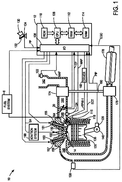
FIG. 1 is a diagram schematically showing a configuration of an internal combustion engine according to the present disclosure,
FIG. 2 is a diagram showing a setting of combustion modes on an operational region defined by a torque and an engine speed;
FIG. 3 is a diagram showing a relation between a combustion limit air-fuel ratio, a control target air-fuel ratio and an intake load factor;
FIG. 4 is a diagram showing an operational region defined by the intake load factor and the engine speed, the operational region being divided into a region where the margin of the control target air-fuel ratio with respect to the combustion limit air-fuel ratio is wide and a region where the margin is narrow;
FIG. 5 is a table showing a relationship among the margin of the control target air-fuel ratio with respect to the combustion limit air-fuel ratio, the variation of the combustion limit air-fuel ratio, and the robustness of the combustion;
FIG. 6 is a diagram showing configurations of maps used in setting of a waiting time for the intake load factor, the engine speed and the variation of the combustion limit air-fuel ratio;
FIG. 7 is a flowchart showing a control flow performed when switching the combustion mode from the stoichiometric mode to the homogeneous lean mode;
FIG. 8 is a time chart showing an example of an operation of the internal combustion engine in the case where the control flow shown in FIG. 7 is performed when switching the combustion mode while maintaining a constant torque;
FIG. 9 is a time chart showing another example of an operation of the internal combustion engine in the case where the control flow shown in FIG. 7 is performed when switching the combustion mode while maintaining a constant torque;
FIG. 10 is a time chart showing another example of an operation of the internal combustion engine in the case where the control flow shown in FIG. 7 is performed when switching the combustion mode while maintaining a constant torque;
FIG. 11 is a time chart showing an example of an operation of the internal combustion engine in the case where the control flow shown in FIG. 7 is performed when switching the combustion mode in response to a decrease of the torque;
FIG. 12 is a time chart showing another example of an operation of the internal combustion engine in the case where the control flow shown in FIG. 7 is performed when switching the combustion mode in response to a decrease of the torque;
FIG. 13 is a time chart showing another example of an operation of the internal combustion engine in the case where the control flow shown in FIG. 7 is performed when switching the combustion mode in response to a decrease of the torque;
FIG. 14 is a flowchart showing a control flow performed when switching the combustion mode from the homogeneous lean mode to the stoichiometric mode;
FIG. 15 is a time chart showing an example of an operation of the internal combustion engine in the case where the control flow shown in FIG. 14 is performed when switching the combustion mode while maintaining a constant torque;
FIG. 16 is a time chart showing another example of an operation of the internal combustion engine in the case where the control flow shown in FIG. 14 is performed when switching the combustion mode while maintaining a constant torque;
FIG. 17 is a time chart showing another example oft an operation of the internal combustion engine in the case where the control flow shown in FIG. 14 is performed when switching the combustion mode while maintaining a constant torque;
FIG. 18 is a flowchart showing a control flow performed when switching the combustion mode from the stoichiometric mode to the homogeneous lean mode according to another embodiment; and
FIG. 19 is a flowchart showing a control flow performed when switching the combustion mode from the homogeneous lean mode to the stoichiometric mode according to another embodiment.
In the following, embodiments of the present disclosure will be described with reference to the drawings. Any mention of a numerical value such as the number, quantity, amount or range of an entity in the embodiments described below is not intended to limit the present disclosure to the numerical value unless otherwise specified or unless it is obvious that the numerical value is identified in principle. In addition, any structure, step or the like described in the embodiments is not essential for the present disclosure unless otherwise specified or unless it is obvious that the structure, step or the like is identified in principle. 1. Summary of Configuration of Internal Combustion Engine
FIG. 1 is a diagram schematically showing a configuration of an internal combustion engine according to the present disclosure. FIG. 1 shows components of an internal combustion engine 1 (referred to simply as an engine hereinafter) projected to a plane perpendicular to a crankshaft. The engine 1 is a spark ignition multi-cylinder engine with a plurality of cylinders 4 . The number and arrangement of the cylinders 4 are not particularly limited. The cylinder 4 contains a piston 8 that reciprocates in the axial direction of the cylinder 4 . In an engine head (not shown), a combustion chamber 6 having a pent roof-like shape, which forms an upper space in the cylinder 4 , is formed.
An intake port 10 and an exhaust port 16 are connected to the combustion chamber 6 . An intake valve 14 is provided at an opening of the intake port 10 into the combustion chamber 6 . The intake valve 14 is driven by an intake variable valve device 15 that can continuously change the valve timing of the intake valve 14 and switch a driving cam between a large working angle cam and a small working angle cam. An exhaust valve 17 is provided at an opening of the exhaust port 16 into the combustion chamber 6 . The exhaust valve 17 is driven by an exhaust variable valve device 18 that can continuously change the valve timing of the exhaust valve 17 and switch a driving cam between a large working angle cam and a small working angle cam.
An intake manifold 11 is connected to the intake port 10 , and the intake manifold distributes air among cylinders after the flow rate of the air is adjusted by a throttle 13 . Each branch pipe of the intake manifold 11 is provided with a tumble control valve 12 , which serves as an air flow control valve. The strength of the tumble flow that occurs in the combustion chamber 6 can be increased by reducing the opening angle of the tumble control valve 12 , and the effective cross-sectional area of the flow channel and thus the intake efficiency can be increased by increasing the opening angle of the tumble control valve 12 . In this embodiment, the opening angle of the tumble control valve 12 is adjusted in two steps: open and close. As a specific index of the strength of the tumble flow, a tumble ratio is used. The tumble ratio is defined as the number of revolutions of the tumble flow in the combustion chamber 6 in a time required for one reciprocation of the piston 8 .
A water jacket 20 in which cooling water flows is provided surrounding the cylinder 4 . The cooling water is circulated in a cooling water circulation circuit 22 that connects the water jacket 20 and a radiator 21 to each other. The temperature of the cooling water can be adjusted by an electronic thermostat 23 provided on the cooling water circulation circuit 22 .
Although not shown, the engine 1 is provided with a port injection valve that injects fuel into the intake port 10 and an in-cylinder injection valve that injects fuel directly into the combustion chamber 6 . The engine 1 can switch between an operation in a homogeneous lean mode and an operation in a stoichiometric mode. In the homogeneous lean mode, the engine operates at a lean air-fuel ratio (an air-fuel ratio of approximately 25, for example) relying on the port injection that provides a highly homogeneous air-fuel mixture or a combination of the port injection as a primary injection and the in-cylinder injection as a secondary injection. The lean combustion in the engine 1 is not a stratified lean combustion in which a layer of an air-fuel mixture with a high fuel concentration is formed around an ignition plug but a homogeneous lean combustion in which an air-fuel mixture with a homogeneous fuel concentration is distributed in the whole of the combustion chamber 6 . In the stoichiometric mode, the engine operates at the theoretical air-fuel ratio, that is, in the stoichiometric combustion mode relying on the in-cylinder injection or a combination of the in-cylinder injection as a primary injection and the port injection as a secondary injection.
Devices and actuators that provide the homogeneous lean mode and the stoichiometric mode are operated by a controller 30 . The controller 30 controls the operation of the engine 1 by operating various devices and actuators of the engine 1 . The controller 30 is an electronic control unit (ECU) that includes at least one CPU, at least one ROM, and at least one RAM. The controller 30 may be constituted by a plurality of ECUs. The controller 30 loads a program from the ROM to the RAM and makes the CPU execute the program to provide various functions involved with engine control. 2. Engine Control in Response to Combustion Mode
FIG. 2 is a diagram showing a relationship between the torque and the engine speed of the engine 1 in different combustion modes of the engine 1 selected by the controller 30 . As shown in this drawing, the stoichiometric mode is selected in a low engine speed region, a high engine speed region, a low torque region and a high torque region, and the homogeneous lean mode is selected in a medium torque and medium engine speed region. The terms “low”, “medium” and “high” used herein to express the magnitude of the engine speed, the torque, the intake load factor and the like mean the relative magnitude in the operational region of the engine 1 and does not mean the absolute magnitude.
In response to the combustion mode selected, the controller 30 performs an air amount control based on operation of the throttle 13 , a fuel injection control based on operation of a fuel injection device (not shown, including the port injection valve and the in-cylinder injection valve), and an ignition control based on operation of an ignition device (not shown, including the ignition plug). The air amount control involves calculating a control target intake load factor from a control target torque and a control target air-fuel ratio and calculating the opening angle of the throttle 13 that achieves the control target intake load factor by using a physical mode. The fuel injection control involves estimating the air amount in the combustion chamber 6 by using a physical model that has, as parameters, operational states of actuators involved with air intake including the throttle 13 and the tumble control valve 12 . A total fuel injection amount is calculated from the estimated air amount and the control target air-fuel ratio, and the fuel injection amount for each injection valve is calculated from a share ratio of each injection valve determined by the combustion mode and the total fuel injection amount. The ignition control involves determining an ignition timing from the control target intake load factor, the control target air-fuel ratio and the like.
The air amount, the fuel injection amount of each injection valve, and the ignition timing are fundamental operation quantities that determine the combustion state. Even at the same torque and the same engine speed, appropriate values of the operation quantities vary between when the engine operates in the stoichiometric combustion mode and when the engine operates in the homogeneous lean combustion mode. Thus, switching from the stoichiometric mode to the homogeneous lean mode is achieved by changing each of the air amount, the fuel injection amount and the ignition timing from an appropriate value for the stoichiometric mode to an appropriate value for the homogeneous lean mode. Similarly, switching from the homogeneous lean mode to the stoichiometric mode is achieved by changing each of the operation quantities from an appropriate value for the homogeneous lean mode to an appropriate value for the stoichiometric mode. The switching of the combustion mode referred to herein means making each of the air amount control, the fuel injection control and the ignition control suitable for the selected combustion mode.
The controller 30 changes settings of operation quantities of at least the tumble control valve 12 , the intake variable valve device 15 , the exhaust variable valve device 18 and the electronic thermostat 23 in response to the switching of the combustion mode as a result of change of the operation quantities described above. This is because these operation quantities have a direct or indirect effect on the combustion state in each combustion mode. More specifically, in operation of the tumble control valve 12 , in the homogeneous lean mode, the tumble control valve 12 is closed to produce a strong tumble flow in the combustion chamber 6 . This is intended not only to increase the turbulence of the air flow in the combustion chamber 6 but also to promote mixing of the fuel and air. In the stoichiometric mode, the tumble control valve 12 is opened to increase the effective cross-sectional area of the flow channel and thus increase the intake efficiency. In operation of the intake variable valve device 15 , in the stoichiometric mode, the valve timing is relatively advanced, and the large working angle cam is used, and in the homogeneous lean mode, the valve timing is relatively delayed, and the small working angle cam is used. In operation of the exhaust variable valve device 18 , in the stoichiometric mode, the valve timing is relatively delayed, and the large working angle cam is used, and in the homogeneous lean mode, the valve timing is relatively advanced, and the small working angle cam is used. In operation of the electronic thermostat 23 , in the stoichiometric mode, the electronic thermostat 23 is opened to relatively reduce the engine water temperature to suppress occurrence of a knocking, and in the homogeneous lean mode, the electronic thermostat 23 is closed to relatively increase the engine water temperature to increase the in-cylinder temperature and thereby promote vaporization of the fuel. 3. Summary of Switching Control of Combustion Mode
From the viewpoint of the fuel economy and the operation performance, switching of the combustion mode is preferably immediately performed when the target operating point of the engine 1 is moved. In this respect, however, it has to be noted that the switching be performed while ensuring stable combustion. If an unstable combustion causes a misfire, the misfire causes not only significant deterioration of the exhaust gas emission performance but also deterioration of the fuel economy and the operation performance.
The unstable combustion that occurs during switching of the combustion mode is caused by the air-fuel ratio temporarily exceeding a combustion limit air-fuel ratio while the air-fuel ratio is changed from the control target air-fuel ratio for the stoichiometric mode to the control target air-fuel ratio for the homogeneous lean mode or while the air-fuel ratio is changed from the control target air-fuel ratio for the homogeneous lean mode to the control target air-fuel ratio for the stoichiometric mode. The combustion limit air-fuel ratio is a limit value on the fuel lean side of the range of the air-fuel ratio in which stable combustion can be achieved, and depends on the intake load factor. A cause of the variation of the air-fuel ratio is deterioration of the precision of the estimation of the air amount based on the physical model. The physical model used for estimating the air amount in the fuel injection control (referred to as an air model) is designed for a steady state. Thus, in a transient state in which the opening angle of the throttle significantly varies, such as during switching of the combustion mode, it is difficult to estimate the air amount with high precision. Since the fuel injection amount is determined based on the estimated air amount, if the estimated air amount deviates from the actual air amount, the control target air-fuel ratio also deviates from the actual air-fuel ratio.
In FIG. 3 , the double line shows a variation of the combustion limit air-fuel ratio (denoted as combustion limit A/F in the drawing) with respect to the intake load factor in the case where the engine speed is constant. In a region where the intake load factor is low, the combustion limit air-fuel ratio significantly varies with respect to the intake load factor, and rapidly increases as the intake load factor increases. In a region where the intake load factor is medium, the combustion limit air-fuel ratio slowly varies with respect to the intake load factor and is kept high. In a region where the intake load factor is high, the combustion limit air-fuel ratio temporarily decreases as the intake load factor increases and, as a result, the combustion limit air-fuel ratio is slightly lower than the intake load factor in the region where the intake load factor is medium.
For the combustion limit air-fuel ratio that varies with respect to the intake load factor as described above, the control target air-fuel ratio in the homogeneous lean mode is set with a certain margin. In FIG. 3 , the solid line shows a variation of the control target air-fuel ratio (denoted as control target A/F in the drawing) in the homogeneous lean mode with respect to the intake load factor in the case where the engine speed is constant. In the following description, the term “control target air-fuel ratio” means the control target air-fuel ratio in the homogeneous lean mode unless otherwise specified. Whereas the combustion limit air-fuel ratio varies with the intake load factor, the variation of the control target air-fuel ratio is reduced in the region where the intake load factor is medium and the region where the intake load factor is high. This is intended to prevent the control target air-fuel ratio from abruptly varying when the intake load factor varies. Thus, the margin of the control target air-fuel ratio with respect to the combustion limit air-fuel ratio is not uniform. Although the margin is wide in the region where the intake load factor is medium, the margin is narrow in the region where the intake load factor is low and the region where the intake load factor is high.
A relationship similar to the relationship between the combustion limit margin and the control target air-fuel ratio for the intake load factor described above also exists for the engine speed. That is, the margin of the control target air-fuel ratio with respect to the combustion limit air-fuel ratio is not uniform with respect to the engine speed. Although the margin is wide in a region where the engine speed is medium, the margin is narrow in the region where the engine speed is low and the region where the engine speed is high. FIG. 4 shows the operational region of the engine 1 defined in a coordinate system in a two-dimensional plane whose coordinate axes show the intake load factor and the engine speed, the operational region being divided into a region where the margin of the control target air-fuel ratio with respect to the combustion limit air-fuel ratio is wide and a region where the margin is narrow. In the following description, the region where the margin of the control target air-fuel ratio with respect to the combustion limit air-fuel ratio is wide is referred to as a wide combustion limit margin region, and the region where the control target air-fuel ratio with respect to the combustion limit air-fuel ratio is narrow is referred to as a narrow combustion limit margin region.
The description continues in the full USPTO document.
About 6,597 words. The USPTO PDF has it with every drawing.
Fees are due 3.5, 7.5 and 11.5 years after grant. This patent expired on May 22, 2026, so the fee marked "not paid" was the one that went unpaid.
INTERNAL COMBUSTION ENGINE
Filed Mar 2017 · published Oct 2017Internal combustion engine
Filed Mar 2017 · granted May 2018Earlier publications, parents and continuations. None of them can still be enforced, or this patent would not be listed.
Prior art cited by the examiner or applicant. Useful when you check your own idea for novelty.
Everything on this page comes from the documents linked above.