Cross-reference to related applications
This is a national phase application based on the PCT International Patent Application No. PCT/JP2015/057330 filed Mar. 12, 2015, claiming priority to Japanese Patent Application No. 2014-050389 filed Mar. 13, 2014, the entire contents of both of which are incorporated herein by reference.
Technical field
The present invention relates to an internal combustion engine.
Background art
In a combustion chamber of an internal combustion engine, an air-fuel mixture of air and fuel is ignited in a compressed state. The compression ratio when compressing the air-fuel mixture is known to have an effect on the output and amount of fuel consumption of the internal combustion engine. It is possible to increase the compression ratio to thereby increase the output torque and improve the heat efficiency. In this regard, it is known that if making the compression ratio too high, knocking and other forms of abnormal combustion will occur. Known in the prior art has therefore been an internal combustion engine comprising a variable compression ratio mechanism changing the compression ratio during the operating period.
The variable compression ratio mechanism can change the volume of a combustion chamber at the time when a piston reaches top dead center to thereby change the compression ratio. If fuel is burned in a combustion chamber, the cylinder internal pressure rises. Further, force acts on members forming the combustion chamber in a direction increasing the combustion chamber in volume. This force also acts on the variable compression ratio mechanism. In particular, this force is liable to be transmitted to a motor or other rotating machine driving the mechanism changing the volume of the combustion chamber.
For this reason, in a variable compression ratio mechanism, it is known to arrange a reverse input blocking clutch blocking rotational force due to the cylinder internal pressure so that the rotational force due to the cylinder internal pressure is not transmitted to an output shaft of the rotating machine. A reverse input blocking clutch has a lock function blocking the rotational force applied to the output shaft of the rotating machine. When changing the mechanical compression ratio, the locked state of the reverse input blocking clutch is released, then the volume of the combustion chamber is changed.
Japanese Patent Publication No. 2005-214088A discloses a variable compression ratio engine able to make a reciprocating operating element advance and retract so as to change the position where the piston reaches top dead center. This variable compression ratio engine is changed in compression ratio by an actuator mechanism. The actuator mechanism comprises a ball screw, a rotation transmission system transmitting rotation of a motor to a nut of the ball screw, and a clutch interposed in the rotation transmission system. This publication discloses to employ a reverse input restricting type of clutch which transmits rotation from an input member to which drive force of the motor is input to a nut and blocks transmission of rotation from the nut to the input member.
Japanese Patent Publication No. 2012-229764 discloses an unlocking device comprising a torque diode blocking a load torque of an output shaft from being transmitted to an input shaft when a torque is transmitted from the input shaft to the output shaft and releasing a locked state of the torque diode. In this unlocking control device, it is disclosed to gradually increase the unlocking torque when the locked state is not released even after continuing to apply a set unlocking torque for a predetermined time. SUMMARY OF INVENTION Technical Problem
When changing the mechanical compression ratio, it is necessary to release the locked state of the reverse input blocking clutch. During operation of the engine, rotational force due to cylinder internal pressure is applied to the reverse input blocking clutch. The cylinder internal pressure changes along with time. The torque required for releasing the locked state of the reverse input blocking clutch therefore changes along with time.
The mechanical compression ratio may be changed not only in the period of driving the engine, but also in the period when the engine is stopped. For example, sometimes the mechanical compression ratio is changed right before starting up the engine so as to detect abnormality of the variable compression ratio mechanism. Further, in a hybrid drive system powered by an internal combustion engine and an electric motor, there is a period during which the engine is temporarily stopped. During this period, sometimes the mechanical compression ratio is changed so as to form an oil film on the surface of the eccentric shafts etc. and avoid seizure of the bearings.
In this way, to release the locked state of a reverse input blocking clutch in all states which occur during both periods when an engine is operating and when it is stopped, it may be considered to select a rotating machine with a large output torque as the rotating machine for driving the input shaft of the reverse input blocking clutch. However, if increasing the capacity of the rotating machine, there are the problems that the power consumption increases or the amount of consumption of fuel by the internal combustion engine increases. Further, there are the problems that the rotating machine becomes larger in size and the locations for installation of the rotating machine become limited.
The present invention has as its object the provision of an internal combustion engine comprising a variable compression ratio mechanism including a reverse input blocking clutch and able to reduce the size of the rotating machine driving the variable compression ratio mechanism.
An internal combustion engine of the present invention comprises a variable compression ratio mechanism able to change a mechanical compression ratio. The variable compression ratio mechanism includes a drive device for changing a volume of a combustion chamber when a piston reaches top dead center, and a control device controlling the drive device. The drive device includes a rotating machine, and a clutch arranged in a drive force transmission path transmitting the rotational force of the rotating machine. The clutch is formed so as to block a reverse input torque applied to an output shaft in a rotation direction causing the mechanical compression ratio to fall. The control device estimates a reverse input torque applied to the output shaft of the clutch, sets a torque gradient to be output by the rotating machine and a continuation time for continuation of increase of torque based on the reverse input torque, and releases a locked state of the clutch based on the torque gradient and the continuation time.
In the above invention, the clutch includes an input shaft to which a rotational force of the rotating machine is input, an output shaft to which the rotational force is transmitted from the input shaft, and an outer race not moving while the clutch is being driven, rollers are arranged between the output shaft and the outer race, the output shaft and the outer race form engagement parts for engaging with the rollers, and the clutch is formed so that when the reverse input torque in the rotation direction causing the mechanical compression ratio to fall acts on the output shaft, the rollers are engaged with the engagement parts and lock the output shaft with the outer race thereby blocking the reverse input torque. The control device makes the input shaft rotate based on the torque gradient and the continuation time to thereby separate the rollers from the engagement parts and release the lock on the output shaft.
In the above invention, the rotating machine includes an electric motor, and the control device changes a duty ratio of current supplied to the electric motor to thereby control the torque gradient and changes a time period for supplying power to the electric motor to thereby control the continuation time.
In the above invention, the variable compression ratio mechanism includes a lubrication oil supplying device supplying lubrication oil to the clutch and a temperature detector detecting a temperature of the lubrication oil, and the control device detects a temperature of the lubrication oil and controls the torque gradient and the continuation time based on the temperature of the lubrication oil.
In the above invention, the engine comprises an accumulator supplying power to the electric motor, and a voltage detector detecting an output voltage of the accumulator, and the control device sets the torque gradient and the continuation time based on a voltage drop allowed for releasing the locked state when detecting an output voltage of the accumulator and the output voltage is lower than a predetermined voltage judgment value.
In the above invention, the engine comprises a support structure including a crankcase, and a cylinder block supported by the support structure, the variable compression ratio mechanism includes shafts interposed between the support structure and cylinder block and including eccentric shafts, and the drive device changes a size of the combustion chamber by making the shafts rotate to change a relative position of the cylinder block with respect to the support structure.
In the above invention, the engine comprises a biasing member biasing the cylinder block in a direction separating from the support structure, and the control device sets the torque gradient and the continuation time based on a biasing force of the biasing member when lowering the mechanical compression ratio in a period during which fuel stops being burned in the combustion chamber.
In the above invention, the engine comprises a cylinder internal pressure detector detecting a cylinder internal pressure, and a rotational force estimating device estimating a reverse input torque applied to the output shaft of the clutch, and the control device detects the cylinder internal pressure when lowering the mechanical compression ratio during the operating period of the internal combustion engine, controls the rotating machine so as to start driving the input shaft of the clutch during the period when the cylinder internal pressure is changing from a local maximum point to a local minimum point, estimates the reverse input torque when an amplitude of vibration of a reverse input torque applied to the output shaft of the clutch is less than a predetermined judgment value, and sets the torque gradient and the continuation time based on the reverse input torque. Advantageous Effects of Invention
According to the present invention, it is possible to provide an internal combustion engine comprising a variable compression ratio mechanism including a reverse input blocking clutch and able to reduce the size of the rotating machine driving the variable compression ratio mechanism.
Brief description of the drawings
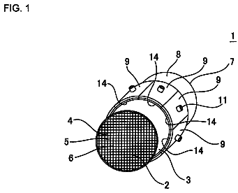
FIG. 1 is a schematic overview of an internal combustion engine in an embodiment.
FIG. 2 is a schematic disassembled perspective view of a variable compression ratio mechanism in an embodiment.
FIG. 3 is a first schematic cross-sectional view of a variable compression ratio mechanism explaining a change of a mechanical compression ratio in an embodiment.
FIG. 4 is a second schematic cross-sectional view of a variable compression ratio mechanism explaining a change of a mechanical compression ratio in an embodiment.
FIG. 5 is a third schematic cross-sectional view of a variable compression ratio mechanism explaining a change of a mechanical compression ratio in an embodiment.
FIG. 6 is a first schematic cross-sectional view of a clutch in an embodiment.
FIG. 7 is a second schematic cross-sectional view of a clutch in an embodiment.
FIG. 8 is a first schematic cross-sectional view of a clutch when lowering a mechanical compression ratio in an embodiment.
FIG. 9 is a second schematic cross-sectional view of a clutch when lowering a mechanical compression ratio in an embodiment.
FIG. 10 is a schematic cross-sectional view of a clutch when raising a mechanical compression ratio in an embodiment.
FIG. 11 is a graph explaining a condition enabling release of a locked state with respect to an input torque applied to a clutch and an application time applying the input torque in an embodiment.
FIG. 12 is a graph explaining a region enabling release of a locked state with respect to an acceleration of an input shaft and continuation time of continuation of increase of an input torque in a clutch of an embodiment.
FIG. 13 is a flow chart of first operational control changing a mechanical compression ratio in an embodiment.
FIG. 14 is a graph of a load applied to a cylinder block by lift springs with respect to an eccentric shaft angle in an embodiment.
FIG. 15 is a graph of an angular coefficient by which a link mechanism transmits rotational force with respect to an eccentric shaft angle in an embodiment.
FIG. 16 is a graph of a reverse input torque of a clutch with respect to an eccentric shaft angle in an embodiment.
FIG. 17 is a graph of an output torque of a motor when changing a duty ratio of a motor in an embodiment.
FIG. 18 is a graph of a friction coefficient at contact surfaces of rollers of a clutch in an embodiment.
FIG. 19 is a schematic view of a power feed device supplying power to a motor of a variable compression ratio mechanism in an embodiment.
FIG. 20 is a graph explaining an area enabling release of a locked state with respect to acceleration of an input shaft and continuation time of continuation of increase of an input torque in a clutch of an embodiment.
FIG. 21 is a flow chart of third operational control changing a mechanical compression ratio in an embodiment.
FIG. 22 is a graph of cylinder internal pressure with respect to a crank angle of an internal combustion engine in an embodiment.
FIG. 23 is a graph of reverse input torque of a clutch with respect to a crank angle of an internal combustion engine in an embodiment.
FIG. 24 is a flow chart of fourth operational control changing a mechanical compression ratio in an embodiment.
Description of embodiments
Referring to FIG. 1 to FIG. 24 , an internal combustion engine in an embodiment will be explained. In the present embodiment, a spark ignition type internal combustion engine mounted in a vehicle will be illustrated for the explanation. The internal combustion engine in the present embodiment comprises a variable compression ratio mechanism able to change a mechanical compression ratio.
FIG. 1 is a schematic view of an internal combustion engine in an embodiment. The internal combustion engine comprises an engine 90 . The engine 90 comprises a support structure including a crankcase 1 . The support structure is formed so as to support a crankshaft. The engine 90 comprises a cylinder block 2 and a cylinder head 3 . At a bore part formed at the inside of the cylinder block 2 , a piston 4 is arranged. At the center part of a top surface of a combustion chamber 5 , a spark plug 6 is arranged. In the present invention, the space surrounded by a crown surface of a piston 4 , a bore part of the cylinder block 2 , and a cylinder head 3 at any position of the piston 4 will be referred to as a “combustion chamber”. Further, as a cylinder internal pressure detector detecting the pressure of a combustion chamber 5 , that is, the cylinder internal pressure, a cylinder internal pressure sensor 23 is arranged.
At the cylinder head 3 , an intake port 8 and exhaust port 10 are formed. At the end part of the intake port 8 , an intake valve 7 is arranged. The intake valve 7 opens and closes by rotation of an intake cam 49 . At the end part of the exhaust port 10 , an exhaust valve 9 is arranged. The intake port 8 is connected through an intake branch tube 11 to a surge tank 12 . At the intake branch tube 11 , a fuel injector 13 for injecting fuel toward the inside of the corresponding intake port 8 is arranged. Note that, instead of being attached to the intake branch tube 11 , the fuel injector 13 may be arranged to directly inject fuel to the combustion chamber 5 .
The surge tank 12 is connected through an intake duct 14 to an air cleaner 15 . At the inside of the intake duct 14 , a throttle valve 17 driven by an actuator 16 is arranged. Further, at the inside of the intake duct 14 , for example, an intake air detector 18 using a hot wire is arranged. On the other hand, the exhaust port 10 is connected through an exhaust manifold 19 to a catalyst device 20 , for example, housing a three-way catalyst. At the exhaust manifold 19 , an air-fuel ratio sensor 21 is arranged.
The internal combustion engine in the present embodiment comprises a variable compression ratio mechanism A able to change the volume of the combustion chamber 5 at the time when the piston 4 is positioned at compression top dead center. The variable compression ratio mechanism A is formed so as to change the relative position of the cylinder block 2 with respect to the crankcase 1 in the cylinder axial direction. Between the crankcase 1 and the cylinder block 2 , biasing members comprised of lift springs 65 are arranged. The lift springs 65 are formed so as to bias the cylinder block 2 in a direction away from the crankcase 1 . Note that, the biasing members are not limited to these. Any members biasing the cylinder block in a direction away from the crankcase may be employed.
At the crankcase 1 and cylinder block 2 , a relative position sensor 22 is attached for detecting the relative position of the cylinder block 2 with respect to the crankcase 1 . From the relative position sensor 22 , an output signal showing a change in distance between the crankcase 1 and cylinder block 2 is output. At the actuator 16 for driving the throttle valve, a throttle opening degree sensor 24 generating an output signal showing an opening degree of the throttle valve is attached.
The control device of an internal combustion engine in the present embodiment includes an electronic control unit 30 . The electronic control unit 30 in the present embodiment is a digital computer. The digital computer includes components connected with each other by a bidirectional bus 31 such as a ROM (read only memory) 32 , RAM (random access memory) 33 , CPU (microprocessor) 34 , input port 35 , and output port 36 .
The output signals of the intake air detector 18 , air-fuel ratio sensor 21 , relative position sensor 22 , cylinder internal pressure sensor 23 , and throttle opening degree sensor 24 are input through corresponding AD converters 37 to the input port 35 . Further, an accelerator pedal 40 has a load sensor 41 generating an output voltage proportional to the amount of depression of the accelerator pedal 40 connected to it. The output voltage of the load sensor 41 is input to a corresponding AD converter 37 to the input port 35 . The output of the load sensor 41 can be used to detect the demanded load. Furthermore, a crank angle sensor 42 generating an output pulse every time the crankshaft rotates by for example 300 is connected to the input port 35 . The output of the crank angle sensor 42 can be used to detect the crank angle and engine speed.
On the other hand, the output port 36 is connected through corresponding drive circuits 38 to the spark plugs 6 , fuel injectors 13 , throttle valve drive actuator 16 , and variable compression ratio mechanism A. These devices are controlled by the electronic control unit 30 .
FIG. 2 is a disassembled perspective view of a variable compression ratio mechanism in the present embodiment. FIG. 3 is a first schematic cross-sectional view of a variable compression ratio mechanism in the present embodiment. Referring to FIG. 2 and FIG. 3 , below the two side walls of the cylinder block 2 , a plurality of projecting parts 50 are formed spaced apart from each other. At each projecting part 50 , a cam insertion hole 51 with a circular cross-sectional shape is formed. On the other hand, at the top wall of the crankcase 1 , a plurality of projecting parts 52 are formed spaced apart from each other to be fit between the projecting parts 50 . At these projecting parts 52 as well, cam insertion holes 53 with circular cross-sectional shapes are formed.
The variable compression ratio mechanism in the present embodiment includes shafts including eccentric shafts comprised of camshafts 54 , 55 . The camshafts 54 , 55 are interposed between the crankcase 1 and cylinder block 2 . On each camshaft 54 , 55 , circular cams 58 are arranged to be inserted in every other cam insertion hole 53 to be able to rotate. These circular cams 58 are coaxial with the axial lines of the camshafts 54 , 55 . On the other hand, at the both sides of each circular cam 58 , as shown in FIG. 3 , eccentric shafts 57 arranged off-centered from the axial lines of the camshafts 54 , 55 extend. At each eccentric shaft 57 , another circular cam 56 is attached off-centered to be able to rotate. As shown in FIG. 2 , circular cams 56 are arranged at the both sides of each circular cam 58 . These circular cams 56 are inserted in the corresponding cam insertion holes 51 to be able to rotate. The cylinder block 2 is supported by the crankcase 1 through the camshafts 54 , 55 including the eccentric shafts 57 .
FIG. 4 shows a second schematic cross-sectional view of a variable compression ratio mechanism in the present embodiment. FIG. 5 shows a third schematic cross-sectional view of a variable compression ratio mechanism in the present embodiment. FIG. 3 to FIG. 5 are cross-sectional views explaining the function of the variable compression ratio mechanism when changing the mechanical compression ratio in normal operation. From the state shown in FIG. 3 , the circular cam 58 arranged on each camshaft 54 , 55 moves in a direction whereby the eccentric shafts 57 approach each other if made to rotate in opposite directions to the other as shown by the arrows 68 . The eccentric shafts 57 rotate about the axial lines of the respective camshafts 54 , 55 . The cylinder block 2 , as shown by the arrow 99 , moves in a direction away from the crankcase 1 . At this time, the circular cams 56 rotate inside the cam insertion holes 51 and, as shown in FIG. 4 , change in the positions of the eccentric shafts 57 from low positions to intermediate height positions. Next, furthermore, if making the circular cams 58 rotate in the direction shown by the arrows 68 , the cylinder block 2 , as shown by the arrow 99 , moves in a direction further away from the crankcase 1 . As a result, as shown in FIG. 5 , the eccentric shafts 57 become the highest position.
FIG. 3 to FIG. 5 show the positional relationship between the center “a” of a circular cam 58 , the center “b” of an eccentric shaft 57 , and the center “c” of a circular cam 56 . As will be understood from a comparison of FIG. 3 to FIG. 5 , the relative position of the crankcase 1 and the cylinder block 2 is determined by the distance between the center “a” of the circular cam 58 and the center “c” of the circular cam 56 . The larger the distance between the center “a” of the circular cam 58 and the center “c” of the circular cam 56 , the further the cylinder block 2 from the crankcase 1 . That is, the variable compression ratio mechanism A changes relative position of the crankcase 1 and cylinder block 2 due to the link mechanism using the rotating cams.
If the cylinder block 2 moves away from the crankcase 1 , the volume of the combustion chamber 5 at the time when the piston 4 is positioned at compression top dead center increases. If the cylinder block 2 approaches the crankcase 1 , the volume of the combustion chamber 5 at the time when the piston 4 is positioned at compression top dead center decreases. Therefore, it is possible to rotate the camshafts 54 , 55 to thereby change the volume of the combustion chamber 5 at the time when the piston 4 is positioned at compression top dead center.
Referring to FIG. 2 , the variable compression ratio mechanism of the present embodiment includes a drive device for rotating the camshafts 54 , 55 for changing the volume of the combustion chambers 5 . The drive device includes a rotating machine comprised of a motor 59 . Furthermore, the drive device includes a clutch 70 , worms 61 , 62 , worm wheels 63 , 64 , etc. The shaft 66 is connected to the output shaft of the motor 59 and input shaft of the clutch 70 . The shaft 60 is connected to the output shaft of the clutch 70 . At the shaft 60 , a pair of worms 61 , 62 with opposite spiral directions are attached so as to make the camshafts 54 , 55 rotate in mutually opposite directions. The worm wheels 63 , 64 engaging with the worms 61 , 62 are fastened to the ends of the camshafts 54 , 55 . Note that, the rotating machine of the drive device is not limited to a motor or other electric motor. Any device able to make the input shaft of the clutch 70 rotate can be employed.
In this embodiment, by driving the motor 59 , it is possible to change the volume of the combustion chamber 5 at the time when the piston 4 is positioned at compression top dead center over a broad range. The variable compression ratio mechanism is controlled by the electronic control unit 30 . The motor 59 making the camshafts 54 , 55 rotate are connected through a corresponding drive circuit 38 to the output port 36 .
In this way, the variable compression ratio mechanism in the present embodiment is formed so that the volume of the combustion chamber 5 at the time when the piston reaches top dead center can be changed by the cylinder block 2 moving relative to the crankcase 1 . In the present embodiment, the compression ratio determined from only the stroke volume of the piston from bottom dead center to top dead center and the volume of a combustion chamber at the time when the piston reaches top dead center will be called the “mechanical compression ratio”. The mechanical compression ratio does not rely on the closing timing of the intake valve etc. and can be shown by (mechanical compression ratio)=(volume of combustion chamber at time when piston reaches top dead center+stroke volume of piston)/(volume of combustion chamber at time when piston reaches top dead center).
In the state shown in FIG. 3 , the volume of the combustion chamber 5 becomes small and the mechanical compression ratio is high. If the amount of intake air is always constant, the actual compression ratio becomes high. As opposed to this, in the state shown in FIG. 5 , the volume of the combustion chamber 5 becomes large and the mechanical compression ratio is low. If the amount of intake air is always constant, the actual compression ratio becomes lower.
The internal combustion engine in the present embodiment can change the mechanical compression ratio during the operating period to thereby change the actual compression ratio. For example, it is possible to use the variable compression ratio mechanism to change the mechanical compression ratio in accordance with the operating state of the internal combustion engine.
Referring to FIG. 3 to FIG. 5 , the eccentric shafts 57 rotate about the axes of the camshafts 54 , 55 , that is, the axes of the circular cams 58 . If lowering the mechanical compression ratio, the eccentric shafts 57 are made to rotate in the directions shown by the arrows 68 . If making the mechanical compression ratio rise, the eccentric shafts 57 are made to rotate in the direction shown by the arrows 69 .
Referring to FIG. 2 , the variable compression ratio mechanism in the present embodiment includes a clutch 70 arranged at the drive force transmission path transmitting the rotational force (output torque) output by the motor 59 to the camshafts 54 , 55 .
The clutch 70 in the embodiment is a so-called “reverse input blocking clutch”. The reverse input blocking clutch in the present embodiment is formed to transmit the rotational force from the input shaft to the output shaft and block the rotational force from the output shaft. That is, the clutch 70 is structured so that the rotational force of the shaft 66 transmitted from the motor 59 is transmitted to the worms 61 , 62 and the rotational force of the shaft 60 transmitted from the worms 61 , 62 is blocked and not transmitted to the motor 59 . In the present embodiment, the torque applied to the input shaft of the clutch 70 due to the torque output by the motor 59 will be called the “input torque of the clutch 70 ”. Further, the torque applied to the output shaft of the clutch 70 through the eccentric shafts 57 due to the force acting on the cylinder block 2 will be called the “reverse input torque of the clutch 70 ”.
The clutch 70 of the present embodiment is arranged between the motor 59 and the worm 62 , but the invention is not limited to this. It can be arranged at any position at the drive force transmitting path transmitting rotational force of the motor 59 to the camshafts 54 , 55 . For example, the clutch 70 may be arranged between the worm wheels 63 , 64 and the camshafts 54 , 55 . In this case, clutches can be arranged at the respective camshafts 54 , 55 .
FIG. 6 is a first schematic cross-sectional view of a clutch in the present embodiment. FIG. 7 is a second schematic cross-sectional view of a clutch in the present embodiment. FIG. 7 is a schematic cross-sectional view along the line X in FIG. 6 .
Referring to FIG. 6 and FIG. 7 , the clutch 70 of the present embodiment includes an outer race 77 . The outer race 77 is fastened to the housing 78 by a screw 85 . The outer race 77 is fastened so as not to move even during drive of the clutch 70 . The clutch 70 has an output shaft 74 . The output shaft 74 rotates about a rotation center axis 88 . The output shaft 74 is formed with hole parts 75 . Several of the hole parts 75 are formed along the circumferential direction of rotation of the output shaft 74 . The output shaft 74 in the present embodiment is formed into a polygonal cross-sectional shape.
The clutch 70 includes an input shaft 71 . The input shaft 71 rotates about the rotation center axis 88 . The input shaft 71 has insertion parts 72 and holding parts 73 . The insertion parts 72 and holding parts 73 rotate together.
The plurality of insertion parts 72 are inserted into the hole parts 75 of the output shaft 74 . The inside diameters of the hole parts 75 are formed so as to be larger than the outside diameters of the insertion parts 72 . Clearances are formed between the insertion parts 72 and the hole parts 75 . The plurality of holding parts 73 are arranged between the outer race 77 and the output shaft 74 . Further, the holding parts 73 face rollers 80 a , 80 b.
In the space between the output shaft 74 and the outer race 77 , rollers 80 a , 80 b are arranged. The rollers 80 a , 80 b in the present embodiment are formed into columnar shapes. Between the rollers 80 a and the rollers 80 b , springs 81 are arranged. The springs 81 bias the rollers 80 a , 80 b in directions away from each other.
Due to the output shaft 74 and the outer race 77 , engagement parts 86 a , 86 b for engaging with the rollers 80 a , 80 b are formed. The engagement parts 86 a , 86 b are parts where the distances between the outer surface of the output shaft 75 and the inner surface of the outer race 77 become gradually narrower along the direction in which the rollers 80 a , 80 b are biased. Further, the engagement parts 86 a , 86 b are formed narrow so that the rollers 80 a , 80 b cannot pass through them.
Next, the operation of the clutch 70 in the present embodiment will be explained. The clutch 70 in the present embodiment transmits rotational force of the motor 59 to the output shaft 74 if that rotational force is input to the input shaft 71 . On the other hand, the clutch 70 is locked and blocks rotational force from the camshaft 54 , 55 sides if this rotational force is transmitted to the output shaft 74 . In particular, the clutch 70 blocks this rotational force if rotational force causing rotation in a direction of rotation where the mechanical compression ratio lowers is transmitted to the worms 61 , 62 .
Referring to FIG. 1 , in the present embodiment, due to the lift springs 65 , the cylinder block 2 is biased in a direction moving away from the crankcase 1 . During the operating period of the internal combustion engine, due to the effect of gravity or the effect of the combustion chamber 5 becoming a negative pressure in the intake stroke of the combustion cycle, force acts in a direction where the cylinder block 2 approaches the crankcase 1 . However, due to the provision of the lift springs 65 , the cylinder block 2 is constantly biased in a direction making it move away from the crankcase 1 and vibration etc. can be kept from occurring at the cylinder block 2 . Furthermore, every time fuel is burned in the combustion chamber 5 , due to the cylinder internal pressure, force acts in a direction where the cylinder block 2 moves away from the crankcase 1 .
The biasing force in a direction where the cylinder block 2 moves away from the crankcase 1 is transmitted to the camshafts 54 , 55 and converted to rotational force. The rotational force generated at the camshafts 54 , 55 is transmitted through the worm wheels 63 , 64 and worms 61 , 62 to the output shaft 74 of the clutch 70 . Referring to FIG. 6 , the arrow 100 is the direction corresponding to the direction by which the cylinder block 2 rises with respect to the crankcase 1 . That is, this shows the rotational direction where the mechanical compression ratio becomes smaller and the combustion chamber 5 at the time when the piston 4 reaches top dead center becomes larger. The cylinder block 2 is constantly acted on by force in a direction making it move away from the crankcase 1 , while the output shaft 74 is acted on by a force in a direction shown by the arrow 100 . That is, a reverse input torque acts in the direction shown by the arrow 100 .
Each roller 80 a is pushed by the spring 81 and contacts the engagement part 86 a . For this reason, a wedge effect occurs at the roller 80 a , the rotation of the output shaft 74 with respect to the outer race 77 is obstructed, and the output shaft 74 is locked. In this way, the clutch 70 can block the rotational force from the output side corresponding to the direction in which the cylinder block 2 moves away from the crankcase 1 . Further, similarly, when a rotational force in a direction opposite to the arrow 100 is applied to the output shaft 74 , each roller 80 b contacts the engagement part 86 b and the output shaft 74 is locked. When not driving the motor 59 , the rollers 80 a , 80 b engage with the engagement parts 86 a , 86 b and the clutch 70 locks the output shaft 74 .
FIG. 8 is a first schematic cross-sectional view of a clutch 70 explaining the operation when lowering the mechanical compression ratio. When lowering the mechanical compression ratio, the cylinder block 2 is made to move in a direction moving away from the crankcase 1 . By driving the motor 59 , the insertion parts 72 of the input shaft 71 rotate in the direction shown by the arrow 101 . Before the insertion parts 72 contact the inside surfaces of the hole parts 75 , the holding parts 73 contact the rollers 80 a.
FIG. 9 is a second schematic cross-sectional view of a clutch 70 explaining the operation when lowering the mechanical compression ratio. By making the input shaft 71 further rotate, the holding parts 73 push against the rollers 80 a . The rollers 80 a separate from the engagement parts 86 a . The output shaft 74 is released from its locked state and can rotate with respect to the outer race 77 in the direction shown by the arrow 101 . The insertion parts 72 of the input shaft 71 rotate in the direction shown by the arrow 101 , whereby the insertion parts 72 push against the hole parts 75 of the output shaft 74 and make the output shaft 74 rotate. At this time, the output shaft 74 rotates in a direction whereby the rollers 80 b move away from the engagement parts 86 b , so the locked state due to the rollers 80 b is also released.
FIG. 10 is a schematic cross-sectional view of a clutch 70 explaining the operation when raising the mechanical compression ratio. When raising the mechanical compression ratio, the cylinder block 2 is made to move in a direction approaching the crankcase 1 . By driving the motor 59 , the insertion parts 72 and holding parts 73 of the input shaft 71 are made to rotate in the direction shown by the arrow 102 .
By making the insertion parts 72 and holding parts 73 of the input shaft 71 rotate in the direction shown by the arrow 102 , the holding parts 73 push against the rollers 80 b . The rollers 80 b separate from the engagement parts 86 b whereby the wedge effect of the rollers 80 b disappears. Next, the insertion parts 72 of the input shaft 71 push against the hole parts 75 of the output shaft 74 whereby the rotational force of the input shaft 71 can be transmitted to the output shaft 74 . The output shaft 74 rotates in the direction shown by the arrow 102 . At this time, the output shaft 74 rotates in a direction whereby the rollers 80 a separate from the engagement parts 86 a , so the locked state of the rollers 80 a is also released. In this way, it is possible to transmit the rotational force of the input shaft 71 to the output shaft 74 .
In this regard, the internal combustion engine of the present embodiment performs control for driving the variable compression ratio mechanism in the period when stopping the engine 90 . Here, “stopping the engine 90 ” shows the state not only when fuel stops being burned in the combustion chambers 5 , but also when the torque output from the engine 90 is zero. That is, it shows the state when the engine speed is zero. Even in such a state where the engine 90 is stopped, for example, sometimes the mechanical compression ratio is changed to confirm the presence of any abnormality in the variable compression ratio mechanism.
Referring to FIG. 1 , in the period when the engine 90 is stopped, fuel stops being burned at the combustion chambers 5 . For this reason, the force applied to the cylinder block 2 due to the cylinder internal pressure is zero. However, due to the lift springs 65 arranged between the crankcase 1 and the cylinder block 2 , the cylinder block 2 is biased in a direction moving away from the crankcase 1 .
Referring to FIG. 2 , the force acting on the cylinder block 2 is input through the camshafts 54 , 55 , worm wheels 63 , 64 , worms 61 , 62 , and shaft 60 to the output shaft 74 of the clutch 70 . The direction of the reverse input torque input to the output shaft 74 at this time is the direction whereby the cylinder block 2 moves away from the crankcase 1 .
Referring to FIG. 6 , even during the period when the engine 90 is stopped, at the clutch 70 , a reverse input torque shown by the arrow 100 is applied to the output shaft 74 . The rollers 80 a engage with the engagement parts 86 a and the transmission of reverse input torque to the input shaft 71 is blocked in this state. That is, the clutch 70 is in a locked state.
When raising the mechanical compression ratio during the stopped period of the engine 90 , similar control as during the operating period of the engine 90 can be used to release the locked state. Further, it is possible to release the locked state of the clutch 70 by a relatively small input torque. That is, as shown in FIG. 10 , by using the motor 59 to make the input shaft 71 rotate in the direction shown by the arrow 102 , the locked state due to the rollers 80 b is released and the mechanical compression ratio can be raised. The output torque of the motor 59 at this time can be controlled to a predetermined set value.
The description continues in the full USPTO document.
 Lapsed, fee not paid8 drawings

