Cross-reference to related applications
Pursuant to 35 U.S.C. § 119(a), this application claims the benefit of earlier filing date and right of priority to Korean Patent Application No. 10-2015-0002968, filed on Jan. 8, 2015, the contents of which are hereby incorporated by reference herein in its entirety.
Background
The present disclosure relates to a terminal and an operating method thereof, and particularly, to a terminal configured to perform an operation according to a case state of a case coupled with the terminal.
Depending on whether terminals are movable, the terminals are divided into mobile/portable terminals and stationary terminals. Again, the terminals may be divided into handheld terminals and vehicle mounted terminals depending on whether users can carry the terminals personally.
As functions of a terminal are diversified, such a terminal may be implemented in a form of a multimedia player having multi-functions, for example, photo or video capturing, playback of music or video files, game plays, and broadcast reception. Then, as terminals are implemented in multimedia device forms, they may become equipped with larger displays than before. Then, since the display of a terminal includes a thin, high-resolution touch panel, it is an expensive component that occupies a greater percentage of a terminal price.
Moreover, as the display of a terminal becomes larger, the terminal is damaged often due to drop or impact to the terminal.
Accordingly, various forms of terminal cases are coupled with terminals and used in order to protect the displays of the terminals from being damaged. Especially, terminal cases in forms that cover the terminal fronts with the case fronts may be used in order to protect the displays of terminals.
However, when a terminal case having the case front that covers the terminal front is used, a user needs to flip the case front of the terminal case in order to use the terminal.
Accordingly, recently, in order to resolve inconvenience of using a terminal that is coupled with a terminal case use, a terminal supports an operation for turning on its display based on a position of a terminal case. Further, a user may check a partial screen of a terminal through a window equipped at the case front of a terminal case.
However, such functions support only some operations of a terminal so that they cannot provide various operations performed by the terminal. In general, in order to perform an operation by a user who uses a terminal coupled with a terminal case, the user needs to flip the case front of the terminal case and go through several input steps.
Accordingly, it is necessary to provide a terminal that can perform various operations based on a state of a terminal case that is coupled with the terminal without requiring additional user inputs.
Summary
Embodiments provide a terminal for recognizing a state of a terminal case coupled with the terminal and performing various operations corresponding to the recognized case state.
In one embodiment, provided is an operating method performed at a terminal coupled with a terminal case. The method includes: determining an operating state of the terminal; recognizing a change of a state of the case with respect to the terminal; and performing an operation based on the determined operating state and the recognized change of the state of the case, wherein the state of the case includes a first case state in which a case front part of the case covers a front portion of the terminal or the case front part is in contact with the front portion of the terminal.
In another embodiment, a terminal coupled with a terminal case includes: a display; a sensing unit configured to sense a position of the case with respect to the terminal; and a control unit configured to: determine an operating state of the terminal; recognize a change of a state of the case based on the sensed position of the case; and perform an operation based on the determined operating state and the recognized change of the state of the case, wherein the state of the case includes a first case state in which a case front part of the case covers a front portion of the terminal or the case front part is in contact with the front portion of the terminal.
The details of one or more embodiments are set forth in the accompanying drawings and the description below. Other features will be apparent from the description and drawings, and from the claims.
Brief description of the drawings
FIG. 1 is a block diagram of a terminal according to an embodiment of the present invention.
FIG. 2 is a view illustrating a terminal case according to an embodiment of the present invention.
FIG. 3 is a view illustrating a terminal case including a magnetic material mounted thereon according to an embodiment of the present invention.
FIG. 4 is a view illustrating a terminal case including a magnetic material mounted thereon according to another embodiment of the present invention.
FIG. 5 is a view illustrating a magnetic sensor of a terminal according to an embodiment of the present invention.
FIG. 6 is a sectional view of a terminal including a plurality of magnetic sensors according to an embodiment of the present invention.
FIG. 7 is a view illustrating a front sensor of a terminal according to an embodiment of the present invention.
FIG. 8 is a view illustrating sensing a front sensor of a terminal according to an embodiment of the present invention.
FIG. 9 is a view illustrating a terminal coupled with a terminal case according to an embodiment of the present invention.
FIG. 10 is a view illustrating sensing a rear sensor of a terminal according to an embodiment of the present invention.
FIG. 11 is a flowchart illustrating an operation method performed at a terminal according to an embodiment of the present invention.
FIG. 12 is a view illustrating a first case state of a terminal case according to an embodiment of the present invention.
FIG. 13 is a view illustrating a second case state of a terminal case according to an embodiment of the present invention.
FIG. 14 is a view illustrating a third case state of a terminal case according to an embodiment of the present invention.
FIG. 15 is a flowchart illustrating a terminal operation according to a first embodiment of the present invention.
FIG. 16 is a view illustrating a terminal screen display in a first case state according to an embodiment of the present invention.
FIG. 17 is a view illustrating a first operation corresponding to a call reception screen according to an embodiment of the present invention.
FIG. 18 is a view illustrating a first screen corresponding to a call termination screen according to an embodiment of the present invention.
FIG. 19 is a view illustrating a second screen corresponding to a call termination screen according to an embodiment of the present invention.
FIG. 20 is a view illustrating a second operation corresponding to a call reception screen according to an embodiment of the present invention.
FIG. 21 is a view illustrating a second window display depending on a third operation of a terminal according to an embodiment of the present invention.
FIG. 22 is a view illustrating an editing operation on a second window according to an embodiment of the present invention.
FIG. 23 is a view illustrating an event execution operation depending on a second window according to an embodiment of the present invention.
FIG. 24 is a view illustrating an event adding operation on a second window according to an embodiment of the present invention.
FIG. 25 is a flowchart illustrating a terminal operation according to a second embodiment of the present invention.
FIG. 26 is a view illustrating a third window display according to an embodiment of the present invention.
FIG. 27 is a view illustrating an event execution operation depending on a third window according to an embodiment of the present invention.
FIG. 28 is a view illustrating an event execution operation depending on a third window according to another embodiment of the present invention.
FIG. 29 is a flowchart illustrating a terminal operation according to a third embodiment of the present invention.
FIG. 30 is a view illustrating a measurement distance, a first reference distance, and a second reference distance according to an embodiment of the present invention.
FIGS. 31 and 32 are views illustrating an operation of a terminal corresponding to a call reception screen according to an embodiment of the present invention.
FIGS. 33 and 34 are views illustrating an operation of a terminal corresponding to a watch screen according to an embodiment of the present invention.
FIGS. 35-37 are views illustrating an operation of a terminal corresponding to a weather screen according to an embodiment of the present invention.
FIGS. 38 and 39 are views illustrating a font size change of a terminal according to an embodiment of the present invention.
Detailed description of the embodiments
Hereinafter, embodiments of the present invention are described in more detail with reference to accompanying drawings and regardless of the drawings symbols, same or similar components are assigned with the same reference numerals and thus overlapping descriptions for those are omitted. The suffixes “module” and “unit” for components used in the description below are assigned or mixed in consideration of easiness in writing the specification and, do not have distinctive meanings or roles by themselves. In the following description, detailed descriptions of well-known functions or constructions will be omitted since they would obscure the invention in unnecessary detail. Additionally, the accompanying drawings are used to help easily understanding embodiments disclosed herein but the technical idea of the present invention is not limited thereto. It should be understood that all of variations, equivalents or substitutes contained in the concept and technical scope of the present invention are also included.
It will be understood that the terms “first” and “second” are used herein to describe various components but these components should not be limited by these terms. These terms are used only to distinguish one component from other components.
In this disclosure below, when one part (or element, device, etc.) is referred to as being ‘connected’ to another part (or element, device, etc.), it should be understood that the former can be ‘directly connected’ to the latter, or ‘electrically connected’ to the latter via an intervening part (or element, device, etc.). It will be further understood that when one component is referred to as being ‘directly connected’ or ‘directly linked’ to another component, it means that no intervening component is present.
The terms of a singular form may include plural forms unless they have a clearly different meaning in the context.
Additionally, in this specification, the meaning of “include,” “comprise,” “including,” or “comprising,” specifies a property, a region, a fixed number, a step, a process, an element and/or a component but does not exclude other properties, regions, fixed numbers, steps, processes, elements and/or components.
Terminals described in this specification may include mobile phones, smartphones, laptop computers, terminals for digital broadcast, personal digital assistants (PDAs), portable multimedia players (PMPs), navigation systems, slate PCs, tablet PCs, ultrabooks, and wearable devices (for example, smartwatchs, smart glasses, and head mounted displays (HMDs)).
However, it is apparent to those skilled in the art that configurations according to embodiments of the present invention disclosed in this specification are applicable to terminals such as digital TVs, desktop computers, and digital signage, except for the case applicable to only terminals.
Then, a structure of a terminal according to an embodiment of the present invention is described with reference to FIG. 1 .
FIG. 1 is a block diagram of a terminal according to an embodiment of the present invention.
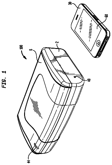
The terminal 100 may include a wireless communication unit 110 , an audio/video (A/V) input unit 120 , a user input unit 130 , a sensing unit 140 , an output unit 150 , a memory 160 , an interface unit 170 , a control unit 180 , and a power supply unit 190 . Since not all components shown in FIG. 1 are essential, a terminal having more or less than the components may be implemented.
Hereinafter, the components will be examined in order.
The wireless communication unit 110 may include at least one module allowing wireless communication between the terminal 100 and a wireless communication system, between the terminal 100 and another terminal 100 , or between the terminal 100 and an external server. Additionally, the wireless communication unit 110 may include at least one module connecting the terminal 100 to at least one network.
The wireless communication unit 110 may include at least one of a broadcast receiving unit 111 , a mobile communication module 112 , a wireless Internet module 113 , a short range communication module 114 , or a location information module 115 .
The broadcast receiving unit 111 may receive a broadcast signal and/or broadcast related information from an external broadcast management server through a broadcast channel.
The broadcast channel may include a satellite channel and a terrestrial channel. The broadcast management server may refer to a server for generating and transmitting broadcast signals and/or broadcast related information or a server for receiving pre-generated broadcast signals and/or broadcast related information and transmitting them to a terminal. The broadcast signals may include TV broadcast signals, radio broadcast signals, and data broadcast signals and also may include broadcast signals in a combination format thereof.
The broadcast related information may refer to information relating to broadcast channels, broadcast programs, or broadcast service providers. The broadcast related information may be provided through a mobile communication network. In such a case, the broadcast related information may be received by the mobile communication module 112 .
The broadcast related information may exist in various formats. For example, the broadcast related information may exist in formats such as Electronic Program Guide (EPG) of Digital Multimedia Broadcasting (DMB) or Electronic Service Guide (ESG) of Digital Video Broadcast-Handheld (DVB-H).
The broadcast receiving unit 111 , for example, may receive digital broadcast signals by using digital broadcast systems such as Digital Multimedia Broadcasting-Terrestrial (DMB-T), Digital Multimedia Broadcasting-Satellite (DMB-S), Media Forward Link Only (MediaFLO), Digital Video Broadcast-Handheld (DVB-H), and Integrated Services Digital Broadcast-Terrestrial (ISDB-T). Of course, the broadcast receiving unit 111 may be configured to be compatible with other broadcast systems in addition to the digital broadcast system.
Broadcast signals and/or broadcast related information received through the broadcast receiving unit 111 may be stored in the memory 160 .
The mobile communication module 112 may transmit/receive wireless signals to/from at least one of base stations, external terminals, and servers. The wireless signals may include various types of data according to a voice call signal, a video call signal, or text/multimedia message transmission.
The wireless Internet module 113 refers to a module for wireless Internet access and may be built in or external to the terminal 100 . Wireless Internet techniques may include Wireless LAN (WLAN) such as Wi-Fi, Wireless broadband (Wibro), World Interoperability for Microwave Access (Wimax), and High Speed Downlink Packet Access (HSDPA).
The short range communication module 114 may refer to a module for short range communication. Short range communication techniques may include Bluetooth, Radio Frequency Identification (RFID), infrared Data Association (IrDA), Ultra Wideband (UWB), ZigBee, and Near Field Communication (NFC).
The location information module 115 is a module for obtaining the location (or the current location) of a terminal and its representative examples include a global positioning system (GPS) module or a Wi-Fi module. For example, a terminal may obtain its position through the GPS module by using a signal transmitted from a GPS satellite. As another example, a terminal may obtain its position through a Wi-Fi module on the basis of information of a wireless access point (AP) transmitting/receiving a wireless signal to/from the Wi-Fi module. If necessary, the position information module 115 may perform a function of another module in the wireless communication unit 110 in order to obtain data on the location of a terminal substitutionally or additionally. The location information module 115 is a module for obtaining the position (or the current position) of a terminal and is not limited to a module directly calculating and obtaining the position of a terminal.
Referring to FIG. 1 , the A/V input unit 120 may be for audio signal or video signal input and may include a camera 121 and a microphone 122 . The camera 121 processes image frames such as a still image or a video obtained by an image sensor in a video call mode or a capturing mode. The processed image frame may be displayed on the display unit 151 .
The image frame processed by the camera 121 may be stored in the memory 160 or transmitted to the outside through the wireless communication unit 110 . The camera 121 may be provided with two or more according to a usage environment.
The microphone 122 may receive external sound signals through a microphone in a call mode, a recording mode, and a voice recognition mode and process them as electrical sound data. In the case of a call mode, the processed voice data may be converted into a format transmittable to a mobile communication base station through the mobile communication module 112 and outputted. Various noise canceling algorithms for removing noise occurring during the reception of external sound signals may be implemented in the microphone 122 .
The A/V input unit 120 may include a camera 121 or an image input unit for image signal input and a microphone 122 or an audio input unit for audio signal input. Voice data or image data collected by the A/V input unit 120 are analyzed and processed as a user's control command.
The user input unit 130 (for example, a touch key and a mechanical key)) is for receiving information from a user.
The sensing unit 140 may include at least one sensor for sensing at least one of information in a terminal, environmental information around a terminal, or user information. For example, the sensing unit 140 may include at least one of a proximity sensor, an illumination sensor, a touch sensor, an acceleration sensor, a magnetic sensor, a G-sensor, a gyroscope sensor, a motion sensor, an RGB sensor, an infrared (IR) sensor, a finger scan sensor, an ultrasonic sensor, an optical sensor (for example, the camera 121 ), a microphone 122 , a battery gauge, an environmental sensor (for example, a barometer, a hygrometer, a thermometer, a radiation sensor, a thermal sensor, and a gas sensor), or a chemical sensor (for example, an electronic noise, a healthcare sensor, and a biometric sensor). Moreover, a terminal disclosed in this specification may combine information sensed by at least two or more sensors among such sensors.
Additionally, the sensing unit 140 may sense a state of a terminal case 200 coupled with the terminal 100 . For example, a state of the terminal case 200 may be sensed through a magnetic sensor. As another example, a state of the terminal case 200 may be sensed through a front magnetic sensor 146 or a rear magnetic sensor 147 included in the sensing unit 140 , as shown in FIG. 6 . Herein, a state of the terminal case 200 may mean the position of a case front part 210 of the terminal case 200 coupled with the terminal 100 . A state sensing of the terminal case 200 of the sensing unit 140 will be described later.
The output unit 150 may be used to generate a visual, auditory, or haptic output and may include at least one of a display unit 151 , a sound output unit 152 , an alarm unit 153 , or a haptic module 154 . The display unit 151 and a touch sensor may form a mutual layer structure or may be formed integrally, so that a touch screen may be implemented. Such a touch screen may serve as the user input unit 123 providing an input interface between the terminal 100 and a user and may provide an output interface between the terminal 100 and a user at the same time.
The display unit 151 may display (output) information processed in the terminal 100 . For example, when a terminal is in a call mode, the display unit 151 may display a call related user interface (UI) or graphic user interface (GUI). When the terminal 100 is in a video call mode or a capture mode, the display unit 151 may display a captured and/or received image, UI, and GUI.
The display unit 151 may include at least one of a liquid crystal display (LCD), a thin film transistor-liquid crystal display (TFT LCD), an organic light-emitting diode (OLED), a flexible display, or a 3D display.
Some displays among them may be configured with a transparent type or a light transmission type to be seen through the displays. This may be referred to as a transparent display and the typical examples of the transparent display may include Transparent OLED (TOLED). The display unit 151 may be configured with a rear structure or a light transmission type structure. Through such a structure, a user may see an object located at the rear of a terminal body through an area that the display unit 151 of a terminal body occupies.
The display unit 151 may be two or more according to an implementation form of the terminal 100 . For example, a plurality of display units may be disposed on one side, being spaced from each other or integrally, or may be disposed at different sides in the terminal 100 .
When the display unit 151 and a sensor for detecting a touch operation (hereinafter referred to as a touch sensor) form a mutual layer structure (hereinafter referred to as a touch screen), the display unit 151 may be used as an input device in addition to an output device. A touch sensor, for example, may have a form of a touch film, a touch sheet, and a touch pad.
The touch sensor may be configured to convert changes in a pressure applied to a specific portion of the display unit 151 or a capacitance generated from a specific portion of the display unit 151 into electrical input signals. The touch sensor may be configured to detect a pressure and a capacitance during touch in addition to a touched position and area.
When there is a touch input applied on the touch sensor, signal(s) corresponding thereto may be transmitted to a touch controller. The touch controller processes the signal(s) and then transmits corresponding data to the control unit 180 . Therefore, the control unit 180 may recognize which area of the display unit 151 is touched.
Additionally, the control unit 180 may determine the type of a user's touch input on the basis of an area, a pressure, and a capacitance during touch. Accordingly, the control unit 180 may distinguish a multi touch using user's finger touch, nail touch, knuckle touch, and a plurality of fingers.
The proximity sensor may be disposed in an inner area of a terminal surrounded by the touch screen or around the touch screen. The proximity sensor refers to a sensor detecting whether there is an object approaching a predetermined detection surface or whether there is an object around by using the strength of an electromagnetic field or infrared, without mechanical contact. The proximity sensor has a longer lifecycle and higher usability than a contact type sensor.
Examples of the proximity sensor may include a transmission-type photoelectric sensor, a direct reflective-type photoelectric sensor, a mirror reflective-type photoelectric sensor, a high-frequency oscillation-type proximity sensor, a capacitive-type proximity sensor, a magnetic-type proximity sensor, and an infrared proximity sensor. When the touch screen is capacitive, it is configured to detect the proximity of a pointer through changes in electric field according to the proximity of the pointer. In this case, the touch screen (or a touch sensor) may be classified as a proximity sensor.
On the other hand, the proximity sensor may include a front sensor 146 for sensing the front direction of the terminal 100 and a rear sensor 147 for sensing the rear direction of the terminal 100 .
For convenience of description, an action for recognizing a pointer is disposed on the touch screen as the pointer is close on the touch screen without contacting the touch screen is called “proximity touch” and an action that the pointer actually contacts the touch screen is called “contact touch”. A position that a pointer is proximity-touched on the touch screen is a position that the pointer vertically corresponds to the touch screen when the pointer is proximity-touched.
The proximity sensor may detect a proximity touch and a proximity touch pattern (for example, a proximity touch distance, a proximity touch direction, a proximity touch speed, a proximity touch time, a proximity touch position, and a proximity touch movement state). Information corresponding to the detected proximity touch operation and proximity touch pattern may be outputted on a touch screen.
The sound output module 152 may output audio data received from the wireless communication unit 110 or stored in the memory 160 in a call signal reception, a call mode, a recording mode, a voice recognition mode, or a broadcast reception mode. The sound output module 152 may output a sound signal relating to a function (for example, a call signal reception sound and a message reception sound) performed by the terminal 100 . The sound output module 152 may include a receiver, a speaker, and a buzzer.
The alarm unit 153 outputs a signal for notifying an event occurrence of the terminal 100 . Examples of an event occurring from a terminal may include a call signal reception, a message reception, a key signal input, and a touch input. The alarm unit 153 may output signals in another format in addition to video signals or audio signals, for example, signals for notifying an event occurrence by vibration. The video signal or audio signal may be outputted through the display unit 151 or the sound output module 152 , so that they 151 and 152 may be classified as part of the alarm unit 153 .
The haptic module 154 generates various haptic effects that a user can feel. A representative example of a haptic effect that the haptic module 154 generates is vibration. The intensity and pattern of a vibration generated by the haptic module 154 may be controllable. For example, the haptic module 154 may synthesize and output different vibrations or output different vibrations sequentially.
The haptic module 154 may generate various haptic effects, for example, effects by a pin arrangement moving vertical to a contact skin surface, injection power or suction power of air through an injection port or a suction port, rubbing a skin surface, electrode contact, stimulus of electrostatic force and effects by the reproduction of cold/warm sense by using a device absorbing or emitting heat.
The haptic module 154 may be implemented to deliver a haptic effect through a direct contact and also allow a user to feel a haptic effect through a muscle sense such as a finger or an arm. The haptic module 154 may be more than two according to a configuration aspect of the terminal 100 .
Additionally, the haptic module 154 may include a vibration device for generating vibration. For example, at least one vibration may be included in the haptic module 154 and may have various forms such as a bar type and a coin type.
Then, the haptic module 154 may be provided at various positions according to the form of the terminal 100 . For example, in the case of a watch type terminal, the haptic module 154 may be included in at least one of a body and a band of the watch type terminal.
Additionally, the memory 160 may store data supporting various functions of the terminal 100 . The memory 160 may store a plurality of application programs (for example, application programs or applications) running on the terminal 100 and also data and commands for operations of the terminal 100 . At least part of such an application program may be downloaded from an external server through a wireless communication. Additionally, at least part of such an application program may be included in the terminal 100 from the time of shipment in order to perform a basic function (for example, an incoming call, a transmission function, and a message reception) of the terminal 100 . Moreover, an application program may be stored in the memory 160 and installed on the terminal 100 , so that it may run to perform an operation (or a function) of the terminal 100 by the control unit 180 .
The memory 160 may include at least one type storage medium among flash memory types, hard disk types, multimedia card micro types, card type memory types (for example, SD or XD memory types), random access memory (RAM) types, static random access memory (SRAM) types, read-only memory (ROM) types, electrically erasable programmable read-only memory (EEPROM) types, programmable read-only memory (PROM) types, magnetic memory types, magnetic disk types, and optical disk types. The terminal 100 may operate in relation to a web storage performing a storage function of the memory 160 on the Internet.
The interface unit 170 may serve as a path to all home devices connected to the terminal 100 . The interface unit 170 may receive data from an external device, receive power and deliver it to each component in the terminal 100 , or transmit data in the terminal 100 to an external device. For example, the interface unit 170 may include a wired/wireless headset port, an external charger port, a wired/wireless data port, a memory card port, a port connecting a device equipped with an identification module, an audio I/O port, a video I/O port, and an earphone port.
The identification module, as a chip storing various information for authenticating the usage authority of the terminal 100 , may include a user identity module (UIM), a subscriber identity module (SIM), and a universal subscriber identity module (USIM). A device equipped with an identification module (hereinafter referred to as an identification device) may be manufactured in a smart card form. Accordingly, the identification device may be connected to the terminal 100 through a port.
When the terminal 100 is connected to an external cradle, the interface unit 170 may become a path through which power of the cradle is supplied to the terminal 100 or a path through which various command signals inputted from the cradle are delivered to the terminal 100 by a user. The various command signals or the power inputted from the cradle may operate as a signal for recognizing that the terminal 100 is accurately mounted on the cradle.
The control unit 180 typically controls an overall operation of a terminal. For example, the control unit 180 may perform control and processing relating to voice call, data communication and video call. The control unit 180 may include a multimedia module 181 for playing multimedia. The multimedia module 181 may be implemented inside the control unit 180 and may be implemented separately from the control unit 180 .
The control unit 180 may perform pattern recognition processing for recognizing handwriting input or drawing input on the touch screen as a text and an image, respectively.
Additionally, the control unit 180 may receive a sensing value for a terminal case 200 from the sensing unit 140 to recognize a state of the terminal case 200 .
The power supply unit 190 may receive external power or internal power under a control of the control unit 180 and may then supply power necessary for an operation of each component.
Various embodiments described herein may be implemented in recording media that can be readable by computers or devices similar thereto through software, hardware, or a combination thereof.
According to the hardware implementation, embodiments described herein may be implemented by using at least one of application specific integrated circuits (ASICs), digital signal processors (DSPs), digital signal processing devices (DSPDs), programmable logic devices (PLDs), field programmable gate arrays (FPGAs), processors, controllers, micro-controllers, microprocessors, and electrical units for performing other functions. In some cases, such embodiments may be implemented by the control unit 180 .
According to the software implementation, embodiments such as procedures or functions may be implemented together with additional software modules for performing at least one function or operation. Software codes may be implemented by a software application written in an appropriate program language. Software codes may be stored in the memory 160 and may be executed by the control unit 180 .
The above-mentioned terminal 100 may be a portable terminal or a vehicle mount terminal. Accordingly, the terminal 100 may be in the form that a user can carry directly or may be in the form that is mounted on a predetermined area.
Moreover, a terminal may expand to a wearable device that can be worn on the body beyond the level that a user mainly grabs the mobile terminal by a hand. Such a wearable device may include a smart watch, a smart glass, and a head-mounted display (HMD).
A terminal case 200 capable of being coupled with the terminal 100 will be described in more detail.
FIG. 2 is a view illustrating a terminal case according to an embodiment of the present invention.
Referring to FIG. 2 , a terminal case 200 may include a case front part 210 and a case rear part 220 . Additionally, the terminal case 200 may include a connection part (not shown) connecting the case front part 210 and the case rear part 220 and may further include a coupling part (not shown) for coupling the terminal case 200 with the terminal 100 .
When each configuration is described in more detail, a coupling part (not shown) is formed to cover the side and rear of the terminal 100 and its front has an open form to allow the detachment of the terminal 100 . Accordingly, a space where the terminal 100 is receivable is formed inside the coupling part (not shown).
An opening part may be formed at the terminal case 200 to expose the camera 121 or other manipulation buttons equipped at one side of the terminal 100 . For example, at least one opening part may be formed at the terminal case 200 to expose cameras or other manipulation buttons equipped on at least one of the front, side, and rear of a terminal.
The case front part 210 may be formed of a plate-shaped member having a form corresponding to the front of the terminal 100 . The case front part 210 may be equipped with an opening part. The opening part of the case front part 210 is formed by cutting a portion of the case front part 210 . The opening part formed by incision may remain as an empty space and according to an embodiment, a transparent film may be attached to the opening part. A touch available film may be used for the transparent film. Additionally, a special film serving as a mirror when a display unit seen through an opening part is turned off may be used as the transparent film. For example, a user may see a picture or image displayed on the display unit 151 of the terminal 100 and may touch the display unit 151 through the front opening part 270 .
Additionally, the case front part 210 may further include an opening part corresponding to a sensor of the terminal 100 . This will be described later.
The case rear part 220 may be formed of a plate-shaped member having a form corresponding to the rear of the terminal 100 . The case rear part 220 may be equipped with an opening part. The opening part of the case rear part 220 is formed by cutting a portion of the case rear part 220 . The opening part formed by incision may remain as an empty space and according to an embodiment, a transparent film may be attached to the opening part. A touch available film may be used for the transparent film. For example, the case rear part 220 may include a first rear opening part 220 a corresponding to the camera 121 of the terminal 100 . Additionally, the case rear part 220 may include a second rear opening part 220 b corresponding to a manipulation button located at the rear of the terminal 100 .
A connection part (not shown) may connect the case front part 210 and the case rear part 220 and may be formed of a flexile material.
Moreover, a magnetic material may be mounted at the case front part 210 . This will be described with reference to FIG. 3 .
FIG. 3 is a view illustrating a terminal case 200 including a magnetic material mounted thereon according to an embodiment of the present invention.
Referring to FIG. 3 , a case front part 210 may include a front magnetic material 231 . When the front magnetic material 231 is included at the case front part 210 , changes in magnetic field may occur as the case front part 210 is opened or closed. The terminal 100 coupled with the terminal case 200 may detect such changes in magnetic field through the sensing unit 140 . This will be described later.
Moreover, a magnetic material may be mounted at the case rear part 220 . This will be described with reference to FIG. 4 .
FIG. 4 is a view illustrating a terminal case including a magnetic material mounted thereon according to another embodiment of the present invention.
Referring to FIG. 4 , a case front part 210 and a case rear part 220 may include a front magnetic material 231 and a rear magnetic material 233 , respectively. When the front magnetic material 231 is included at the case front part 210 , changes in magnetic field may occur as the case front part 210 is opened or closed. When the rear magnetic material 233 is included at the case rear part 220 , the terminal 100 coupled with the terminal case 200 may detect such changes in magnetic field through the sensing unit 140 as the case front part 210 is opened and closed. In more detail, the sensing unit 140 may detect changes in magnetic field in the front or rear direction of the terminal 100 . For example, the sensing unit 140 may detect a magnetic field for each of the front magnetic material 231 and the rear magnetic material 233 when the case front part 210 is disposed at the front of the terminal 100 . Additionally, the sensing unit 140 may detect a magnetic field for each of the front magnetic material 231 and the rear magnetic material 233 when the case front part 210 is disposed at the rear of the terminal 100 . Additionally, the sensing unit 140 may detect a magnetic field for each of the front magnetic material 231 and the rear magnetic material 233 when the case front part 210 is not disposed at the front or rear of the terminal 100 . This will be described later.
Moreover, when the case front part 210 is disposed at the rear of the terminal 100 , the front magnetic material 231 may be coupled with the rear magnetic material 233 magnetically.
Hereinafter, the sensing unit 140 for sensing a magnetic material included in the terminal case 200 will be described in more detail with reference to FIGS. 5 and 6 .
FIG. 5 is a view illustrating a magnetic sensor of a terminal according to an embodiment of the present invention.
The description continues in the full USPTO document.
 Lapsed, fee not paid17 drawings