Field
This relates generally to evaluating embedded personalized systems on user devices and, more specifically, to privacy-preserving distributed evaluation frameworks for embedded personalized systems on user devices.
Background
Intelligent automated assistants (or digital assistants) can provide a beneficial interface between human users and electronic devices. Such assistants can allow users to interact with devices or systems using natural language in spoken and/or text forms. For example, a user can provide a speech input containing a user request to a digital assistant operating on an electronic device. The digital assistant can interpret the user's intent from the speech input and operationalize the user's intent into tasks. The tasks can then be performed by executing one or more services of the electronic device, and a relevant output responsive to the user request can be returned to the user.
Digital assistants can utilize various statistical systems for processing and responding to user requests. For example, digital assistants can utilize speech recognition systems, machine translation systems, natural language understanding systems, and speech synthesis systems. The accuracy and robustness of these statistical systems can be enhanced through personalization of the systems. In particular, the underlying statistical models utilized by the statistical systems can be tailored towards a specific user by training the statistical models with user data. For example, text input received from a user can be used to generate a personalized language model for a speech recognition system. This can enable the speech recognition system to better recognize unique words or phrases (e.g., specific names or locations) that may be less common in general speech, but frequently used by the user.
Personalizing statistical systems with user data can, however, raise privacy concerns. For example, users may not want their personal attributes or characteristics reflected in the personalized statistical models to be shared with a third party. One solution for preserving the user's privacy can be to embed the personalized statistical systems on the user's device. In particular, the personalized statistical models can be generated and stored on the user's device. Further, the personalized results obtained from the personalized statistical models can remain on the user's device. Third-party access to the user's personal data can thus be restricted, which can preserve the user's privacy. However, such restricted access can make it difficult to evaluate embedded personalized statistical systems. For example, it can be difficult to tune the underlying models and algorithms of the embedded personalized statistical systems for optimal performance when access the embedded personalized statistical systems is restricted.
Summary
Systems and processes for evaluating embedded personalized systems are provided. In one example process, instructions that define an experiment associated with a personalized speech recognition system can be received. The instructions can define one or more experimental parameters. In accordance with the received instructions, a second personalized speech recognition system can be generated based on the personalized speech recognition system and the one or more experimental parameters. Additionally, the plurality of user speech samples can be processed using the second personalized speech recognition system to generate a plurality of speech recognition results and a plurality of accuracy scores corresponding to the plurality of speech recognition results. Second instructions can be received based on the plurality of accuracy scores. In accordance with the second instructions, the second speech recognition system can be activated. User speech input can be received. The user speech input can be processed using the activated second personalized speech recognition system to generate a speech recognition result. A response to the user speech input can be outputted based on the speech recognition result.
Brief description of the drawings
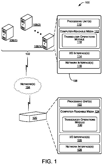
FIG. 1 is a block diagram illustrating a system and environment for implementing a digital assistant according to various examples.
FIG. 2A is a block diagram illustrating a portable multifunction device implementing the client-side portion of a digital assistant according to various examples.
FIG. 2B is a block diagram illustrating exemplary components for event handling according to various examples.
FIG. 3 illustrates a portable multifunction device implementing the client-side portion of a digital assistant according to various examples.
FIG. 4 is a block diagram of an exemplary multifunction device with a display and a touch-sensitive surface according to various examples.
FIG. 5A illustrates an exemplary user interface for a menu of applications on a portable multifunction device according to various examples.
FIG. 5B illustrates an exemplary user interface for a multifunction device with a touch-sensitive surface that is separate from the display according to various examples.
FIG. 6A illustrates a personal electronic device according to various examples.
FIG. 6B is a block diagram illustrating a personal electronic device according to various examples.
FIG. 7A is a block diagram illustrating a digital assistant system or a server portion thereof according to various examples.
FIG. 7B illustrates the functions of the digital assistant shown in FIG. 7A according to various examples.
FIG. 7C illustrates a portion of an ontology according to various examples.
FIG. 8 is a block diagram illustrating a system for evaluating embedded personalized systems according to various examples.
FIGS. 9A-B illustrate a process for evaluating embedded personalized systems according to various examples.
FIG. 10 illustrates a functional block diagram of an electronic device according to various examples.
Detailed description
In the following description of examples, reference is made to the accompanying drawings in which it is shown by way of illustration specific examples that can be practiced. It is to be understood that other examples can be used, and structural changes can be made, without departing from the scope of the various examples.
Statistical systems, such as speech recognition systems or natural language understanding systems, can require iterative tuning in order to optimize performance. For example, each tuning iteration requires adjusting one or more parameters in the statistical system and then evaluating the results to determine whether the adjustment improved the performance of the statistical system. As discussed above, access to embedded personalized statistical systems on user devices is restricted to preserve the privacy of the user. Such restricted access can, for example, prevent system developers from evaluating the outcome of adjustments made to the embedded personalized statistical system. This makes it difficult to optimize the performance of embedded personalize statistical systems.
In accordance with some exemplary systems and processes described herein, embedded personalized statistical systems on user devices are evaluated and optimized in a privacy preserving manner. In one such example process, instructions that define an experiment associated with a personalized speech recognition system are received by a user device. The instructions define one or more experimental parameters. In accordance with the received instructions, a second personalized speech recognition system is generated based on the personalized speech recognition system and the one or more experimental parameters. Additionally, the plurality of user speech samples are processed using the second personalized speech recognition system to generate a plurality of speech recognition results and a plurality of accuracy scores corresponding to the plurality of speech recognition results. The plurality of accuracy scores are confidence scores indicating the likelihood of the speech recognition result given the respective user speech sample. The plurality of accuracy scores are sent to a remote server for evaluation. Since the confidence scores are merely likelihood values and contain no personal information, the privacy of the user is preserved. Based on the plurality of accuracy scores, a system developer determines whether the second personalized speech recognition system should be activated. For example, if the plurality of accuracy scores indicate an improvement in the performance of the second personalized speech recognition system over the personalized speech recognition system, the system developer sends second instructions to the user device to activate the second personalized speech recognition system. The second instructions are received by the user device, and, in accordance with the second instructions, the second personalized speech recognition system is activated such that subsequent speech input is processed using the second personalized speech recognition system. By iteratively evaluating experimental parameters in this manner, the personalized speech recognition system on the user device is tuned for optimal performance while still preserving the privacy of the user.
Although the following description uses terms “first,” “second,” etc. to describe various elements, these elements should not be limited by the terms. These terms are only used to distinguish one element from another. For example, a first speech input could be termed a second speech input, and, similarly, a second speech input could be termed a first speech input, without departing from the scope of the various described examples. The first speech input and the second speech input can both be speech inputs and, in some cases, can be separate and different inputs.
The terminology used in the description of the various described examples herein is for the purpose of describing particular examples only and is not intended to be limiting. As used in the description of the various described examples and the appended claims, the singular forms “a,” “an,” and “the” are intended to include the plural forms as well, unless the context clearly indicates otherwise. It will also be understood that the term “and/or” as used herein refers to and encompasses any and all possible combinations of one or more of the associated listed items. It will be further understood that the terms “includes,” “including,” “comprises,” and/or “comprising,” when used in this specification, specify the presence of stated features, integers, steps, operations, elements, and/or components, but do not preclude the presence or addition of one or more other features, integers, steps, operations, elements, components, and/or groups thereof.
The term “if” may be construed to mean “when” or “upon” or “in response to determining” or “in response to detecting,” depending on the context. Similarly, the phrase “if it is determined” or “if [a stated condition or event] is detected” may be construed to mean “upon determining” or “in response to determining” or “upon detecting [the stated condition or event]” or “in response to detecting [the stated condition or event],” depending on the context.
1. System and Environment
FIG. 1 illustrates a block diagram of system 100 according to various examples. In some examples, system 100 can implement a digital assistant. The terms “digital assistant,” “virtual assistant,” “intelligent automated assistant,” or “automatic digital assistant” can refer to any information processing system that interprets natural language input in spoken and/or textual form to infer user intent, and performs actions based on the inferred user intent. For example, to act on an inferred user intent, the system can perform one or more of the following: identifying a task flow with steps and parameters designed to accomplish the inferred user intent, inputting specific requirements from the inferred user intent into the task flow; executing the task flow by invoking programs, methods, services, APIs, or the like; and generating output responses to the user in an audible (e.g., speech) and/or visual form.
Specifically, a digital assistant can be capable of accepting a user request at least partially in the form of a natural language command, request, statement, narrative, and/or inquiry. Typically, the user request can seek either an informational answer or performance of a task by the digital assistant. A satisfactory response to the user request can be a provision of the requested informational answer, a performance of the requested task, or a combination of the two. For example, a user can ask the digital assistant a question, such as “Where am I right now?” Based on the user's current location, the digital assistant can answer, “You are in Central Park near the west gate.” The user can also request the performance of a task, for example, “Please invite my friends to my girlfriend's birthday party next week.” In response, the digital assistant can acknowledge the request by saying “Yes, right away,” and then send a suitable calendar invite on behalf of the user to each of the user's friends listed in the user's electronic address book. During performance of a requested task, the digital assistant can sometimes interact with the user in a continuous dialogue involving multiple exchanges of information over an extended period of time. There are numerous other ways of interacting with a digital assistant to request information or performance of various tasks. In addition to providing verbal responses and taking programmed actions, the digital assistant can also provide responses in other visual or audio forms, e.g., as text, alerts, music, videos, animations, etc.
As shown in FIG. 1 , in some examples, a digital assistant can be implemented according to a client-server model. The digital assistant can include client-side portion 102 (hereafter “DA client 102 ”) executed on user device 104 and server-side portion 106 (hereafter “DA server 106 ”) executed on server system 108 . DA client 102 can communicate with DA server 106 through one or more networks 110 . DA client 102 can provide client-side functionalities such as user-facing input and output processing and communication with DA server 106 . DA server 106 can provide server-side functionalities for any number of DA clients 102 each residing on a respective user device 104 .
In some examples, DA server 106 can include client-facing I/O interface 112 , one or more processing modules 114 , data and models 116 , and I/O interface to external services 118 . The client-facing I/O interface 112 can facilitate the client-facing input and output processing for DA server 106 . One or more processing modules 114 can utilize data and models 116 to process speech input and determine the user's intent based on natural language input. Further, one or more processing modules 114 perform task execution based on inferred user intent. In some examples, DA server 106 can communicate with external services 120 through network(s) 110 for task completion or information acquisition. I/O interface to external services 118 can facilitate such communications.
User device 104 can be any suitable electronic device. For example, user devices can be a portable multifunctional device (e.g., device 200 , described below with reference to FIG. 2 A), a multifunctional device (e.g., device 400 , described below with reference to FIG. 4 ), or a personal electronic device (e.g., device 600 , described below with reference to FIG. 6A-B .) A portable multifunctional device can be, for example, a mobile telephone that also contains other functions, such as PDA and/or music player functions. Specific examples of portable multifunction devices can include the iPhone®, iPod Touch®, and iPad® devices from Apple Inc. of Cupertino, Calif. Other examples of portable multifunction devices can include, without limitation, laptop or tablet computers. Further, in some examples, user device 104 can be a non-portable multifunctional device. In particular, user device 104 can be a desktop computer, a game console, a television, or a television set-top box. In some examples, user device 104 can include a touch-sensitive surface (e.g., touch screen displays and/or touchpads). Further, user device 104 can optionally include one or more other physical user-interface devices, such as a physical keyboard, a mouse, and/or a joystick. Various examples of electronic devices, such as multifunctional devices, are described below in greater detail.
Examples of communication network(s) 110 can include local area networks (LAN) and wide area networks (WAN), e.g., the Internet. Communication network(s) 110 can be implemented using any known network protocol, including various wired or wireless protocols, such as, for example, Ethernet, Universal Serial Bus (USB), FIREWIRE, Global System for Mobile Communications (GSM), Enhanced Data GSM Environment (EDGE), code division multiple access (CDMA), time division multiple access (TDMA), Bluetooth, Wi-Fi, voice over Internet Protocol (VoIP), Wi-MAX, or any other suitable communication protocol.
Server system 108 can be implemented on one or more standalone data processing apparatus or a distributed network of computers. In some examples, server system 108 can also employ various virtual devices and/or services of third-party service providers (e.g., third-party cloud service providers) to provide the underlying computing resources and/or infrastructure resources of server system 108 .
In some examples, user device 104 can communicate with DA server 106 via second user device 122 . Second user device 122 can be similar or identical to user device 104 . For example, second user device 122 can be similar to devices 200 , 400 , or 600 described below with reference to FIGS. 2A, 4, and 6A -B. User device 104 can be configured to communicatively couple to second user device 122 via a direct communication connection, such as Bluetooth, NFC, BTLE, or the like, or via a wired or wireless network, such as a local Wi-Fi network. In some examples, second user device 122 can be configured to act as a proxy between user device 104 and DA server 106 . For example, DA client 102 of user device 104 can be configured to transmit information (e.g., a user request received at user device 104 ) to DA server 106 via second user device 122 . DA server 106 can process the information and return relevant data (e.g., data content responsive to the user request) to user device 104 via second user device 122 .
In some examples, user device 104 can be configured to communicate abbreviated requests for data to second user device 122 to reduce the amount of information transmitted from user device 104 . Second user device 122 can be configured to determine supplemental information to add to the abbreviated request to generate a complete request to transmit to DA server 106 . This system architecture can advantageously allow user device 104 having limited communication capabilities and/or limited battery power (e.g., a watch or a similar compact electronic device) to access services provided by DA server 106 by using second user device 122 , having greater communication capabilities and/or battery power (e.g., a mobile phone, laptop computer, tablet computer, or the like), as a proxy to DA server 106 . While only two user devices 104 and 122 are shown in FIG. 1 , it should be appreciated that system 100 can include any number and type of user devices configured in this proxy configuration to communicate with DA server system 106 .
Although the digital assistant shown in FIG. 1 can include both a client-side portion (e.g., DA client 102 ) and a server-side portion (e.g., DA server 106 ), in some examples, the functions of a digital assistant can be implemented as a standalone application installed on a user device. In addition, the divisions of functionalities between the client and server portions of the digital assistant can vary in different implementations. For instance, in some examples, the DA client can be a thin-client that provides only user-facing input and output processing functions, and delegates all other functionalities of the digital assistant to a backend server.
2. Electronic Devices
Attention is now directed toward embodiments of electronic devices for implementing the client-side portion of a digital assistant. FIG. 2A is a block diagram illustrating portable multifunction device 200 with touch-sensitive display system 212 in accordance with some embodiments. Touch-sensitive display 212 is sometimes called a “touch screen” for convenience and is sometimes known as or called a “touch-sensitive display system.” Device 200 includes memory 202 (which optionally includes one or more computer-readable storage mediums), memory controller 222 , one or more processing units (CPUs) 220 , peripherals interface 218 , RF circuitry 208 , audio circuitry 210 , speaker 211 , microphone 213 , input/output (I/O) subsystem 206 , other input control devices 216 , and external port 224 . Device 200 optionally includes one or more optical sensors 264 . Device 200 optionally includes one or more contact intensity sensors 265 for detecting intensity of contacts on device 200 (e.g., a touch-sensitive surface such as touch-sensitive display system 212 of device 200 ). Device 200 optionally includes one or more tactile output generators 267 for generating tactile outputs on device 200 (e.g., generating tactile outputs on a touch-sensitive surface such as touch-sensitive display system 212 of device 200 or touchpad 455 of device 400 ). These components optionally communicate over one or more communication buses or signal lines 203 .
As used in the specification and claims, the term “intensity” of a contact on a touch-sensitive surface refers to the force or pressure (force per unit area) of a contact (e.g., a finger contact) on the touch-sensitive surface, or to a substitute (proxy) for the force or pressure of a contact on the touch-sensitive surface. The intensity of a contact has a range of values that includes at least four distinct values and more typically includes hundreds of distinct values (e.g., at least 256). Intensity of a contact is, optionally, determined (or measured) using various approaches and various sensors or combinations of sensors. For example, one or more force sensors underneath or adjacent to the touch-sensitive surface are, optionally, used to measure force at various points on the touch-sensitive surface. In some implementations, force measurements from multiple force sensors are combined (e.g., a weighted average) to determine an estimated force of a contact. Similarly, a pressure-sensitive tip of a stylus is, optionally, used to determine a pressure of the stylus on the touch-sensitive surface. Alternatively, the size of the contact area detected on the touch-sensitive surface and/or changes thereto, the capacitance of the touch-sensitive surface proximate to the contact and/or changes thereto, and/or the resistance of the touch-sensitive surface proximate to the contact and/or changes thereto are, optionally, used as a substitute for the force or pressure of the contact on the touch-sensitive surface. In some implementations, the substitute measurements for contact force or pressure are used directly to determine whether an intensity threshold has been exceeded (e.g., the intensity threshold is described in units corresponding to the substitute measurements). In some implementations, the substitute measurements for contact force or pressure are converted to an estimated force or pressure, and the estimated force or pressure is used to determine whether an intensity threshold has been exceeded (e.g., the intensity threshold is a pressure threshold measured in units of pressure). Using the intensity of a contact as an attribute of a user input allows for user access to additional device functionality that may otherwise not be accessible by the user on a reduced-size device with limited real estate for displaying affordances (e.g., on a touch-sensitive display) and/or receiving user input (e.g., via a touch-sensitive display, a touch-sensitive surface, or a physical/mechanical control such as a knob or a button).
As used in the specification and claims, the term “tactile output” refers to physical displacement of a device relative to a previous position of the device, physical displacement of a component (e.g., a touch-sensitive surface) of a device relative to another component (e.g., housing) of the device, or displacement of the component relative to a center of mass of the device that will be detected by a user with the user's sense of touch. For example, in situations where the device or the component of the device is in contact with a surface of a user that is sensitive to touch (e.g., a finger, palm, or other part of a user's hand), the tactile output generated by the physical displacement will be interpreted by the user as a tactile sensation corresponding to a perceived change in physical characteristics of the device or the component of the device. For example, movement of a touch-sensitive surface (e.g., a touch-sensitive display or trackpad) is, optionally, interpreted by the user as a “down click” or “up click” of a physical actuator button. In some cases, a user will feel a tactile sensation such as an “down click” or “up click” even when there is no movement of a physical actuator button associated with the touch-sensitive surface that is physically pressed (e.g., displaced) by the user's movements. As another example, movement of the touch-sensitive surface is, optionally, interpreted or sensed by the user as “roughness” of the touch-sensitive surface, even when there is no change in smoothness of the touch-sensitive surface. While such interpretations of touch by a user will be subject to the individualized sensory perceptions of the user, there are many sensory perceptions of touch that are common to a large majority of users. Thus, when a tactile output is described as corresponding to a particular sensory perception of a user (e.g., an “up click,” a “down click,” “roughness”), unless otherwise stated, the generated tactile output corresponds to physical displacement of the device or a component thereof that will generate the described sensory perception for a typical (or average) user.
It should be appreciated that device 200 is only one example of a portable multifunction device, and that device 200 optionally has more or fewer components than shown, optionally combines two or more components, or optionally has a different configuration or arrangement of the components. The various components shown in FIG. 2A are implemented in hardware, software, or a combination of both hardware and software, including one or more signal processing and/or application-specific integrated circuits.
Memory 202 may include one or more computer-readable storage mediums. The computer-readable storage mediums may be tangible and non-transitory. Memory 202 may include high-speed random access memory and may also include non-volatile memory, such as one or more magnetic disk storage devices, flash memory devices, or other non-volatile solid-state memory devices. Memory controller 222 may control access to memory 202 by other components of device 200 .
In some examples, a non-transitory computer-readable storage medium of memory 202 can be used to store instructions (e.g., for performing aspects of processes described below) for use by or in connection with an instruction execution system, apparatus, or device, such as a computer-based system, processor-containing system, or other system that can fetch the instructions from the instruction execution system, apparatus, or device and execute the instructions. In other examples, the instructions (e.g., for performing aspects of the processes described below) can be stored on a non-transitory computer-readable storage medium (not shown) of the server system 108 or can be divided between the non-transitory computer-readable storage medium of memory 202 and the non-transitory computer-readable storage medium of server system 108 . In the context of this document, a “non-transitory computer-readable storage medium” can be any medium that can contain or store the program for use by or in connection with the instruction execution system, apparatus, or device.
Peripherals interface 218 can be used to couple input and output peripherals of the device to CPU 220 and memory 202 . The one or more processors 220 run or execute various software programs and/or sets of instructions stored in memory 202 to perform various functions for device 200 and to process data. In some embodiments, peripherals interface 218 , CPU 220 , and memory controller 222 may be implemented on a single chip, such as chip 204 . In some other embodiments, they may be implemented on separate chips.
RF (radio frequency) circuitry 208 receives and sends RF signals, also called electromagnetic signals. RF circuitry 208 converts electrical signals to/from electromagnetic signals and communicates with communications networks and other communications devices via the electromagnetic signals. RF circuitry 208 optionally includes well-known circuitry for performing these functions, including but not limited to an antenna system, an RF transceiver, one or more amplifiers, a tuner, one or more oscillators, a digital signal processor, a CODEC chipset, a subscriber identity module (SIM) card, memory, and so forth. RF circuitry 208 optionally communicates with networks, such as the Internet, also referred to as the World Wide Web (WWW), an intranet and/or a wireless network, such as a cellular telephone network, a wireless local area network (LAN) and/or a metropolitan area network (MAN), and other devices by wireless communication. The RF circuitry 208 optionally includes well-known circuitry for detecting near field communication (NFC) fields, such as by a short-range communication radio. The wireless communication optionally uses any of a plurality of communications standards, protocols, and technologies, including but not limited to Global System for Mobile Communications (GSM), Enhanced Data GSM Environment (EDGE), high-speed downlink packet access (HSDPA), high-speed uplink packet access (HSUPA), Evolution, Data-Only (EV-DO), HSPA, HSPA+, Dual-Cell HSPA (DC-HSPDA), long term evolution (LTE), near field communication (NFC), wideband code division multiple access (W-CDMA), code division multiple access (CDMA), time division multiple access (TDMA), Bluetooth, Bluetooth Low Energy (BTLE), Wireless Fidelity (Wi-Fi) (e.g., IEEE 802.11a, IEEE 802.11b, IEEE 802.11g, IEEE 802.11n, and/or IEEE 802.11ac), voice over Internet Protocol (VoIP), Wi-MAX, a protocol for e mail (e.g., Internet message access protocol (IMAP) and/or post office protocol (POP)), instant messaging (e.g., extensible messaging and presence protocol (XMPP), Session Initiation Protocol for Instant Messaging and Presence Leveraging Extensions (SIMPLE), Instant Messaging and Presence Service (IMPS)), and/or Short Message Service (SMS), or any other suitable communication protocol, including communication protocols not yet developed as of the filing date of this document.
Audio circuitry 210 , speaker 211 , and microphone 213 provide an audio interface between a user and device 200 . Audio circuitry 210 receives audio data from peripherals interface 218 , converts the audio data to an electrical signal, and transmits the electrical signal to speaker 211 . Speaker 211 converts the electrical signal to human-audible sound waves. Audio circuitry 210 also receives electrical signals converted by microphone 213 from sound waves. Audio circuitry 210 converts the electrical signal to audio data and transmits the audio data to peripherals interface 218 for processing. Audio data may be retrieved from and/or transmitted to memory 202 and/or RF circuitry 208 by peripherals interface 218 . In some embodiments, audio circuitry 210 also includes a headset jack (e.g., 312 , FIG. 3 ). The headset jack provides an interface between audio circuitry 210 and removable audio input/output peripherals, such as output-only headphones or a headset with both output (e.g., a headphone for one or both ears) and input (e.g., a microphone).
In some examples, audio circuitry 210 can include a buffer (e.g., memory) to store audio data received from peripherals interface 218 . The buffer can also store audio data converted from the electrical signals of microphone 213 . The buffer can be a circular buffer. The circular buffer can be a first-in first-out (FIFO) buffer that continually overwrites its contents. The buffer may be of any size, such as for example 10 or 20 seconds. In some examples, audio circuitry 210 can utilize memory 202 to store audio data.
I/O subsystem 206 couples input/output peripherals on device 200 , such as touch screen 212 and other input control devices 216 , to peripherals interface 218 . I/O subsystem 206 optionally includes display controller 256 , optical sensor controller 258 , intensity sensor controller 259 , haptic feedback controller 261 , and one or more input controllers 260 for other input or control devices. The one or more input controllers 260 receive/send electrical signals from/to other input control devices 216 . The other input control devices 216 optionally include physical buttons (e.g., push buttons, rocker buttons, etc.), dials, slider switches, joysticks, click wheels, and so forth. In some alternate embodiments, input controller(s) 260 are, optionally, coupled to any (or none) of the following: a keyboard, an infrared port, a USB port, and a pointer device such as a mouse. The one or more buttons (e.g., 308 , FIG. 3 ) optionally include an up/down button for volume control of speaker 211 and/or microphone 213 . The one or more buttons optionally include a push button (e.g., 306 , FIG. 3 ).
A quick press of the push button may disengage a lock of touch screen 212 or begin a process that uses gestures on the touch screen to unlock the device, as described in U.S. patent application Ser. No. 11/322,549, “Unlocking a Device by Performing Gestures on an Unlock Image,” filed Dec. 23, 2005, U.S. Pat. No. 7,657,849, which is hereby incorporated by reference in its entirety. A longer press of the push button (e.g., 306 ) may turn power to device 200 on or off. The user may be able to customize a functionality of one or more of the buttons. Touch screen 212 is used to implement virtual or soft buttons and one or more soft keyboards.
Touch-sensitive display 212 provides an input interface and an output interface between the device and a user. Display controller 256 receives and/or sends electrical signals from/to touch screen 212 . Touch screen 212 displays visual output to the user. The visual output may include graphics, text, icons, video, and any combination thereof (collectively termed “graphics”). In some embodiments, some or all of the visual output may correspond to user-interface objects.
Touch screen 212 has a touch-sensitive surface, sensor, or set of sensors that accepts input from the user based on haptic and/or tactile contact. Touch screen 212 and display controller 256 (along with any associated modules and/or sets of instructions in memory 202 ) detect contact (and any movement or breaking of the contact) on touch screen 212 and convert the detected contact into interaction with user-interface objects (e.g., one or more soft keys, icons, web pages, or images) that are displayed on touch screen 212 . In an exemplary embodiment, a point of contact between touch screen 212 and the user corresponds to a finger of the user.
Touch screen 212 may use LCD (liquid crystal display) technology, LPD (light emitting polymer display) technology, or LED (light emitting diode) technology, although other display technologies may be used in other embodiments. Touch screen 212 and display controller 256 may detect contact and any movement or breaking thereof using any of a plurality of touch sensing technologies now known or later developed, including but not limited to capacitive, resistive, infrared, and surface acoustic wave technologies, as well as other proximity sensor arrays or other elements for determining one or more points of contact with touch screen 212 . In an exemplary embodiment, projected mutual capacitance sensing technology is used, such as that found in the iPhone® and iPod Touch® from Apple Inc. of Cupertino, Calif.
A touch-sensitive display in some embodiments of touch screen 212 may be analogous to the multi-touch sensitive touchpads described in the following U.S. Pat. No. 6,323,846 (Westerman et al.), U.S. Pat. No. 6,570,557 (Westerman et al.), and/or U.S. Pat. No. 6,677,932 (Westerman), and/or U.S. Patent Publication 2002/0015024A1, each of which is hereby incorporated by reference in its entirety. However, touch screen 212 displays visual output from device 200 , whereas touch-sensitive touchpads do not provide visual output.
A touch-sensitive display in some embodiments of touch screen 212 may be as described in the following applications:
U.S. patent application Ser. No. 11/381,313, “Multipoint Touch Surface Controller,” filed May 2, 2006;
U.S. patent application Ser. No. 10/840,862, “Multipoint Touchscreen,” filed May 6, 2004;
U.S. patent application Ser. No. 10/903,964, “Gestures For Touch Sensitive Input Devices,” filed Jul. 30, 2004;
U.S. patent application Ser. No. 11/048,264, “Gestures For Touch Sensitive Input Devices,” filed Jan. 31, 2005;
U.S. patent application Ser. No. 11/038,590, “Mode-Based Graphical User Interfaces For Touch Sensitive Input Devices,” filed Jan. 18, 2005;
U.S. patent application Ser. No. 11/228,758, “Virtual Input Device Placement On A Touch Screen User Interface,” filed Sep. 16, 2005;
U.S. patent application Ser. No. 11/228,700, “Operation Of A Computer With A Touch Screen Interface,” filed Sep. 16, 2005;
U.S. patent application Ser. No. 11/228,737, “Activating Virtual Keys Of A Touch-Screen Virtual Keyboard,” filed Sep. 16, 2005; and
U.S. patent application Ser. No. 11/367,749, “Multi-Functional Hand-Held Device,” filed Mar. 3, 2006. All of these applications are incorporated by reference herein in their entirety.
Touch screen 212 may have a video resolution in excess of 100 dpi. In some embodiments, the touch screen has a video resolution of approximately 160 dpi. The user may make contact with touch screen 212 using any suitable object or appendage, such as a stylus, a finger, and so forth. In some embodiments, the user interface is designed to work primarily with finger-based contacts and gestures, which can be less precise than stylus-based input due to the larger area of contact of a finger on the touch screen. In some embodiments, the device translates the rough finger-based input into a precise pointer/cursor position or command for performing the actions desired by the user.
In some embodiments, in addition to the touch screen, device 200 may include a touchpad (not shown) for activating or deactivating particular functions. In some embodiments, the touchpad is a touch-sensitive area of the device that, unlike the touch screen, does not display visual output. The touchpad may be a touch-sensitive surface that is separate from touch screen 212 or an extension of the touch-sensitive surface formed by the touch screen.
Device 200 also includes power system 262 for powering the various components. Power system 262 may include a power management system, one or more power sources (e.g., battery, alternating current (AC)), a recharging system, a power failure detection circuit, a power converter or inverter, a power status indicator (e.g., a light-emitting diode (LED)) and any other components associated with the generation, management and distribution of power in portable devices.
The description continues in the full USPTO document.
 Lapsed, fee not paid25 drawings