Lapsed, fee not paid5 drawings
Cameras, Displays & Optics · US 9,972,247 B2
Power supply device and display device including the same
A power supply device and a display device including the same disclosed.
US 9,972,256 B2 · Assignee: Shenzhen China Star Optoelectronics Technology Co., Ltd · Inventors: Kang; Chih-tsung et al.
Sheet 1 of 4 from the published document. All sheets in the USPTO PDF
A method for driving a liquid crystal panel comprises providing a liquid crystal panel with a plurality of pixel units in a matrix with M rows and N columns, wherein each of the pixel unit has at least a blue sub-pixel, dividing the liquid crystal panel into multiple display units, wherein each display unit comprises two of the pixel units, providing a gray level value, B, to the blue sub-pixels of each of the display units with a higher gray level value, BH, and a lower gray level value, BL, to the blue sub-pixels respectively, wherein the combination of BH and BL results the blue sub-pixels in the display unit to approach a predetermined Gamma Curve, and γ=1.8˜2.4 at a perspective viewing angle. This invention also discloses a liquid display panel comprising the driving method mentioned above.
All 4 drawing sheets from the published document, cropped to the drawing.
What the patent claimed, word for word. All of it is now free to use.
This invention is related the liquid crystal display. More particularly, it's related to a liquid crystal panel and driving method thereof. 2. The Related Arts
LCD (liquid Crystal Display) is a flat and thin display device. It is composed of a certain quantity of color, black and white pixels disposed in front of a light source or a reflector. LCD is currently widely accepted and becomes the mainstream display device due to its low power consumption, high display quality, compact size and light weight. It's widely adopted in various electronic device, such as computing devices, mobile phones, or digit photo frames. The wide viewing angle technology is one of the hot spots of the LCD industry. However, the color shift issue inevitably occurs while viewing at a large angle.
To solve this color shift issue, a 2D1G technology is adapted. 2D1G means a technology to divide each pixel into a main pixel and a sub pixel. The main pixel and the sub pixel have different areas. The main pixel and sub pixel of each pixel are connected to the same gate line and different data lines respectively. By inputting different signal (gray level value) via the different data lines to the main pixel and the sub pixel, it generates different display brightness and brightness at a large angel to lower the color shift issues while viewing at a large angle. However, the data lines are doubled after dividing each pixel into a main pixel and a sub pixel. The aperture ratio would be reduced to affect the transmittance, and the display quality would be lowered as well.
In view of this, an object of the invention is to provide a liquid crystal panel and a driving method by changing the driving method of the liquid crystal panel, simulating 2D1G display panel behavior in the conventional RGB three pixels in the liquid crystal panel to reduce the side view or perspective color shift problems arising.
To achieve the above object, the present invention employs the following technical solutions:
A method for driving a liquid crystal panel comprises providing a liquid crystal panel with a plurality of pixel units in a matrix with M rows and N columns, wherein each of the pixel unit has at least a blue sub-pixel, dividing the liquid crystal panel into multiple display units, wherein each display unit comprises two of the pixel units, providing a gray level value, B, to the blue sub-pixels of each of the display units with a higher gray level value, BH, and a lower gray level value, BL, to the blue sub-pixels respectively, wherein the combination of BH and BL results the blue sub-pixels in the display unit to approach a predetermined Gamma Curve, and γ=1.8˜2.4 at a perspective viewing angle.
Preferably, the pixel units in the display unit are adjacent to each other.
Preferably, the pixel units in the display unit are located in the same column row and in different columns which are spaced apart by another.
Preferably, the pixel units in the display unit are located in the same column row and in different columns which are adjacent to each other and the pixel unit in the same row and the column which is adjacent receive higher BH than the other pixel unit in the display unit.
Preferably, the pixel units in the display unit are located in the same column and in different rows which are adjacent to each other and the pixel unit in the same column and the row which is adjacent to receive higher BH than the other pixel unit in the display unit.
Preferably, the step of providing a gray level value, B, to the blue sub-pixels of each of the display units with a higher gray level value, BH, and a lower gray level value, BL further comprises:
S 101 , acquiring a relationship between the gray level value B.sub.0 of the blue sub-pixel at a front viewing angle α and the actual brightness LvαB.sub.0 in the curve B.sub.0−LvαB.sub.0;
S 102 , acquiring a relationship between the gray level value B.sub.0 of the blue sub-pixel at a perspective viewing angle β and the actual brightness LvβB.sub.0 in the curve B.sub.0−LvβB.sub.0;
S 103 , acquiring the relation curve B−LvαB and B−LvβB under the gray level value B and a theoretical brightness LvB at the front viewing angle α and the perspective viewing angle β in accordance with the equation
( B 255 ) γ = Lv α B Lv α ( 255 ) and ( B 255 ) γ = Lv β B Lv β ( 255 ) , wherein the Lvα
and Lvβ
are looked up from the relation curves B.sub.0−LvαB.sub.0 and B.sub.0−LvβB.sub.0.
S 104 , BH and BL of the gray level value B to the blue sub pixels in the display unit are in accordance with the following equations: Δ1= LvαB+LvαB−Lv α( BH )− Lv α( BL ); Δ2= LvβB+LvβB−Lv β( BH )− Lv β( BL ); y=Δ 1.sup.2+Δ2.sup.2;
Wherein y is the minimum, LvαB and LvβB are looked up from curves B−LvαB and B−LvβB, Lvα(BH) and Lvα(BL) are looked up from B.sub.0−LvαB.sub.0, and Lvβ(BH) and Lvβ(BL) are looked up from B.sub.0−LvβB.sub.0; and
S 105 , resetting a look up table (LUT) for each of the gray level value B of the blue sub-pixels in the display unit to acquire a combination of BH and BL in accordance with S 104 .
Preferably, the front viewing angle α is 0° and the perspective viewing angle β is 30˜80°.
Preferably, the front viewing angle α is 0° and the perspective viewing angle β is 60°.
Preferably, the pixel unit further comprises a red sub-pixel and a green-sub pixel, and the data signals of the red sub-pixel and the green sub-pixel is constant while resetting the data line signal of the blue sub-pixel.
Preferably, the predetermined Gamma curve is γ=2.2.
This invention also discloses a liquid display panel comprising a gate controller, a source controller, and an active area having a plurality of pixel units in a matrix with M rows and N columns and at least one blue sub-pixel in each pixel unit, wherein the driving method of the liquid crystal display is followed by the method mentioned above.
The beneficial effects:
The present invention provides a liquid crystal panel and a driving method, the traditional three-pixel LCD panel RGB analog 2D1G panel display by changing the driving method to reduce color shift problem generated when the side view or perspective, without comparing small aperture ratio LCD panel was not to protect the quality of the liquid crystal panel.
The detailed descriptions accompanying drawings and the embodiment of the present invention are as follows, which allows the technical solutions and other beneficial effects of the present invention more obvious.
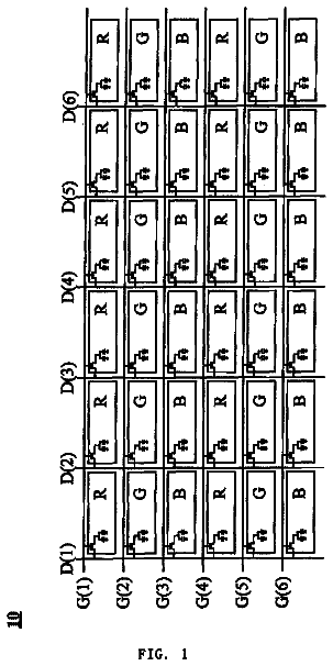
FIG. 1 is a schematic structural view of the embodiment of a liquid crystal panel in the present invention.
FIG. 2 is a schematic structural view of the embodiment of a pixel unit in the present invention.
FIG. 3 is an exemplary illustration of a driving method of a data signal to the display unit in one embodiment of the present invention
FIG. 4 provides an actual brightness curve of the blue sub-pixel at a front viewing angle and a perspective viewing angle of the liquid crystal panel in one embodiment of the invention.
FIG. 5 is a schematic diagram to illustrate one of the dividing methods of the display unit in the present invention.
FIG. 6 is a schematic diagram to illustrate another of the dividing methods of the display unit in the present invention.
FIG. 7 is a schematic diagram to illustrate another of the dividing methods of the display unit in the present invention.
FIG. 8 is a schematic diagram to illustrate another of the dividing methods of the display unit in the present invention.
In order to more clearly describe the technical solutions and the effects in the present invention, the preferred embodiment of the present invention accompanying drawings are described in detail as follows.
With reference FIG. 1 and FIG. 2 , the conventional liquid crystal panel comprises an active area 1 having a plurality of pixel units 5 a / 5 b in a matrix with M rows and N columns, a gate controller 2 , and a source controller 3 . The gate controller 2 provides a scan signal to the pixel unit 5 a / 5 b via a plurality of data lines and each of the pixel units 5 a / 5 b comprises a red sub-pixel 51 , a green sub-pixel 52 , and a blue sub-pixel 53 .
The present embodiment is achieved by changing the method for driving a liquid crystal panel, analog 2D1G panel display in three RGB pixels as a conventional liquid crystal panel, to reduce color shift problems when a side view or perspective.
To achieve this, with reference to FIG. 1 and FIG. 3 , the active area 1 of the liquid crystal panel is divided into a plurality of display units 4 . Each display unit 4 comprises a first pixel unit 5 a and a second pixel unit 5 b . While driving the liquid crystal panel, for the gray level value B of the blue sub-pixels 53 which is required by the display unit, this embodiment provides a higher gray level value BH to the blue sub-pixel of the first pixel unit 5 a , and a lower gray level value BL to the blue sub-pixel of the second pixel unit 5 b . The combination of BL and BH makes the brightness curve of the sub-pixels 53 of the display unit approach a predetermined Gamma (γ) curve at a perspective viewing angle. The Gamma (γ) curve is determined upon the actual requirement of the liquid display panel. In an embodiment, γ could be 1.8˜2.4. FIG. 3 is an exemplary illustration of a driving method of a data signal to the display unit 4 . With reference to FIG. 3 , in the two pixel units 5 a / 5 b of the display unit 4 , the data signals of R and G to the red sub-pixel 51 and the green sub-pixel 52 are kept consistently while resetting the data signal BH and BL of the blue sub-pixels 53 .
wherein the front viewing angle α is 0° and the perspective viewing angle β is 30˜80°.
With reference to FIGS. 1-3 , the step of providing a gray level value, B, to the blue sub-pixels of each of the display units with a higher gray level value, BH, and a lower gray level value, BL further comprising:
S 101 , acquiring a relationship between the gray level value B.sub.0 of the blue sub-pixel at a front viewing angle α and the actual brightness LvαB.sub.0 in the curve B.sub.0−LvαB.sub.0;
S 102 , acquiring a relationship between the gray level value B.sub.0 of the blue sub-pixel at a perspective viewing angle β and the actual brightness LvβB.sub.0 in the curve B.sub.0−LvβB.sub.0;
S 103 , calculate to obtain the gray level B of the blue sub-pixel 53 at the front viewing angle α and the perspective viewing angle β, B−Lv0B and B−Lv60B, respectively in the LvB relationship curve B−LvαB and B−LvβB in accordance with the equations:
( B 255 ) 2.2 = Lv 0 B Lv 0 ( 255 ) and ( B 255 ) 2.2 = Lv 60 B Lv 60 ( 255 ) . Lvα
and Lvβ
are respectively looked up from the relation curve B.sub.0−LvαB.sub.0 and B.sub.0−LvβB.sub.0.
S 104 , while the gray level value B of the blue sub-pixel units is required by the display unit 4 , the gray level value BH in the blue sub-pixel 53 of the first pixel unit 5 a and the gray level value BL in the blue sub-pixel 53 of the second pixel unit 5 b would satisfy the following equations: Δ1= LvαB+LvαB−Lv α( BH )− Lv α( BL ); Δ2= LvβB+LvβB−Lv β( BH )− Lv β( BL ); y=Δ 1.sup.2+Δ2.sup.2;
wherein y is the minimum, LvαB and LvβB are looked up from curves B−LvαB and B−LvβB, Lvα(BH) and Lvα(BL) are looked up from B.sub.0−LvαB.sub.0, and Lvβ(BH) and Lvβ(BL) are looked up from B.sub.0−LvβB.sub.0.
S 105 , resetting a look up table (LUT) for each of the gray level value B of the blue sub-pixels in the display unit to acquire a combination of BH and BL in accordance with S 104 .
The following embodiment describes the gray level value B and combination of divided gray level value BH and BL at the γ=2.2 in the Gamma curve, the front viewing angle α=0 and the perspective angle β=60°.
First, acquire the gray level value B.sub.0 of the blue sub-pixel 53 at the front viewing angle α=0° and the actual brightness Lv0B.sub.0 in accordance the relationship curve B.sub.0−Lv60B.sub.0 at the perspective viewing angle δ=60°. Please refer to FIG. 4 . FIG. 4 illustrates a relationship curve, wherein the gray level of the liquid crystal level comprises 256 gray levels, from 0 to 255.
Subsequently, calculate the gray level B of the blue sub-pixel 53 at the front viewing angle α=0° and the perspective viewing angle β=60°, B−Lv0B and B−Lv60B, respectively in the LvB relationship curve B−Lv0B and B−Lv60B in accordance with the equations:
( B 255 ) 2.2 = Lv 0 B Lv 0 ( 255 ) and ( B 255 ) 2.2 = Lv 60 B Lv 60 ( 255 ) . In the aforementioned equations, acquire the brightness at B.sub.0=255 in the relationship curve B.sub.0−Lv0B.sub.0 at the front viewing angle α=0° and the brightness at B.sub.0=255 in the relationship curve B.sub.0−Lv60B.sub.0 at the front viewing angle β=60°.
Moreover, if the display unit 4 requires a gray level value B in the blue sub-pixel 54 (the original gray level inputs to the blue sub-pixels in the first pixel unit 5 a and the second pixel unit 5 b are both B), instead of B, the input of the gray level value to the blue sub-pixel 53 in the first pixel unit 5 a is BH, and the input of the gray level value to the blue sub-pixel 53 in the second pixel unit 5 b is BL in accordance with the following equations: Δ1= Lv 0 B+Lv 0 B−Lv 0( BH )− Lv 0( BL ); Δ2= Lv 60 B+Lv 60 B−Lv 60( BH )− Lv 60( BL ); y=Δ 1.sup.2+Δ2.sup.2;
While the gray level value B of the blue sub-pixel is confirmed, look up the value Lv0B and Lv60B in the theoretical brightness curves, B−Lv0B and B−Lv60B. Meanwhile, look up Lv0(BH) and Lv0(BL) in the actual brightness curve B.sub.0−Lv0B.sub.0, and Lv60(BH) and Lv60(BL) in the actual brightness curve B.sub.0−Lv60B.sub.0 to make y being minimum for obtaining the corresponding gray level value BH and BL.
At last, obtain a corresponding combination of BH and BL according to the aforementioned calculation for each gray level value B of the blue sub-pixel 53 is required by the display unit, and reset the look up table of the blue sub-pixel 53 in the liquid crystal panel. During driving the liquid crystal panel, if the gray level value B of the blue sub-pixels 53 is required by the display unit 53 when display a first picture, obtain the gray level value to the blue sub-pixel 53 in the first pixel unit 5 a is BH, and the gray level value to the blue sub-pixel 53 in the second pixel unit 5 b is BL.
The layout of the first pixel unit 5 a and the second pixel unit 5 b in the display unit 4 could be in the same row and in the adjacent columns. Since the gray level values of the first pixel unit 5 a and the second pixel unit 5 b are derived from the same gray level value B, the difference is large and incurs the difference of the resolution in the horizontal direction in such layout. While the BL is extremely low, it would cause the loss of the resolution. Besides, in such layout, there is a whole row of the first pixel units 5 a for receiving the higher gray level value BH and a whole row of the second pixel units 5 b for receiving the lower gray level value BL. This would cause further the resolution loss.
For solving the issues mentioned above, this invention provides several embodiments of layout of the first pixel unit 5 a and the second pixel unit 5 b:
the first pixel unit 5 a and the second pixel unit 5 b are disposed in the pixel units in the adjacent rows and columns. Specifically, with reference to FIG. 5 , the first pixel unit 5 a is the pixel unit in the m-th row and the n-th column, the second pixel unit 5 b is the pixel unit in the (m+1)-th row and the (n+1)-th column, and the first pixel unit 5 a and the second pixel unit 5 b are formed a display unit. The other two pixel units in the (m+1)-th row and n-th column and in the m-th row and (n+1)-th column are formed another display unit. While the gray level value to the blue sub-pixel of the pixel unit in the m-th row and n-th column is BH 1 , the gray level value to the blue sub-pixel of the pixel unit in the (m+1)-th row and (n+1)-th column is BL 1 . In another display unit, the gray level value to the blue sub-pixel of the pixel unit in the (m+1)-th row and n-th column is BH 2 and the gray level value to the blue sub-pixel of the pixel unit in the m-th row and (n+1)-th column is BL 2 , wherein m=1, 3, 5 . . . , M and n=1, 3, 5 . . . , N.
According the aforementioned layout of the first pixel unit 5 a and the second pixel unit 5 b , the higher gray level value BH and the lower gray level value BL derived from the same gray level value B are inputted to two of the blue sub-pixels in the adjacent pixels which belongs to different rows to reduce the resolution loss in the horizontal directions. Even BH 1 and BL 2 are inputted to the adjacent two pixel units in the same rows, the difference would not be large since BH 1 and BL 2 are derived from different gray level value B.
the first pixel unit 5 a and the second pixel unit 5 b are disposed in the same row and in different columns which is spaced by another. Specifically, with reference to FIG. 6 , the first pixel unit is the pixel unit in the m-th row and the n-th column, and the second pixel unit 5 b is the pixel unit in the m-th row and the (n+2)-th pixel unit. The aforementioned first pixel unit 5 a and the second pixel unit 5 b are formed a display unit. The pixel unit in the m-th row and the (n+1)-th column, and the pixel unit in the m-th row and the (n+3)-th column are formed another display unit. While the gray level value to the blue sub-pixel of the pixel unit in the m-th row and n-th column is BH 1 , the gray level value to the blue sub-pixel of the pixel unit in the m-th row and (n+2)-th column is BL 1 . In another display unit, the gray level value to the blue sub-pixel of the pixel unit in the m-th row and (n+1)-th column is BH 2 and the gray level value to the blue sub-pixel of the pixel unit in the m-th row and (n+3)-th column is BL 2 , wherein m=1, 2, 3 . . . , M and n=1, 4, 9 . . . , N.
According the aforementioned layout of the first pixel unit 5 a and the second pixel unit 5 b , the higher gray level value BH and the lower gray level value BL (BH 1 /BL 1 and BH 2 /BL 2 ) derived from the same gray level value B are inputted to two of the blue sub-pixels in the adjacent pixels which belongs to different rows to reduce the resolution loss in the horizontal directions.
the first pixel unit 5 a and the second pixel unit 5 b are disposed in the same row and in adjacent columns respectively. For the pixel unit which receives the lower gray level value BL, there is another pixel unit receiving higher gray level value BH in the same column and in the adjacent row. For the pixel unit which receives the higher gray level value BH, there is another pixel unit receiving lower gray level value BL in the same column and in the adjacent row. Specifically, with reference to FIG. 7 , the first pixel unit 5 a is the pixel unit in the m-th row and the n-th column, and the second pixel unit 5 b is the pixel unit in the m-th row and the (n+1)-th column. The aforementioned first pixel unit 5 a and the second pixel unit 5 b are formed a display unit. The pixel unit in the (m+1)-th row and the n-th column, and the pixel unit in the (m+1)-th row and the (n+1)-th column are formed another display unit. While the gray level value to the blue sub-pixel of the pixel unit in the m-th row and n-th column is BH 1 , the gray level value to the blue sub-pixel of the pixel unit in the m-th row and (n+1)-th column is BL 1 . In another display unit, the gray level value to the blue sub-pixel of the pixel unit in the (m+1)-th row and n-th column is BL 2 and the gray level value to the blue sub-pixel of the pixel unit in the (m+1)-th row and (n+1)-th column is BH 2 , wherein m=1, 2, 3 . . . , M and n=1, 3, 5 . . . , N.
According the aforementioned layout of the first pixel unit 5 a and the second pixel unit 5 b , the higher gray level value BH and the lower gray level value BL (BH 1 /BL 1 and BH 2 /BL 2 ) derived from the same gray level value B are inputted to two of the blue sub-pixels in the adjacent pixels which belongs to the same row. However, in the two adjacent rows, the higher gray level value BH 1 and the lower gray level value BL 2 are complementary and the lower gray level value BL 1 and the higher gray level value BH 2 are complementary. Therefore, in general, the higher gray level value BH and lower gray level value BL are spaced by each other in the horizontal and vertical directions to reduce the resolution loss.
The first pixel unit 5 a and the second pixel unit 5 b are disposed in the same column and in adjacent rows respectively. For the pixel unit which receives the lower gray level value BL, there is another pixel unit receiving higher gray level value BH in the same row and in the adjacent columns. Specifically, with reference to FIG. 8 , the first pixel unit 5 a is the pixel unit in the m-th row and the n-th column, and the second pixel unit 5 b is the pixel unit in the (m+1)-th row and the n-th pixel unit. The aforementioned first pixel unit 5 a and the second pixel unit 5 b are formed a display unit. The pixel unit in the m-th row and the (n+1)-th column, and the pixel unit in the (m+1)-th row and the (n+1)-th column are formed another display unit. While the gray level value to the blue sub-pixel of the pixel unit in the m-th row and n-th column is BH 1 , the gray level value to the blue sub-pixel of the pixel unit in the (m+1)-th row and n-th column is BL 1 . In another display unit, the gray level value to the blue sub-pixel of the pixel unit in the m-th row and (n+1)-th column is BL 2 and the gray level value to the blue sub-pixel of the pixel unit in the (m+1)-th row and (n+1)-th column is BH 2 , wherein m=1, 2, 3 . . . , M and n=1, 3, 5 . . . , N.
According the aforementioned layout of the first pixel unit 5 a and the second pixel unit 5 b , the higher gray level value BH and the lower gray level value BL (BH 1 /BL 1 and BH 2 /BL 2 ) derived from the same gray level value B are inputted to two of the blue sub-pixels in the adjacent pixels which belongs to the different rows. (For human eyes, there is no resolution loss while the gray level value difference is large in the same column and the two adjacent rows.) Therefore, in general, the higher gray level value BH and lower gray level value BL are spaced by each other in the horizontal and vertical directions to reduce the resolution loss.
The liquid crystal panel and the driving method mention above comprises dividing the liquid crystal panel into multiple display units, wherein each display unit comprises two of the pixel units, and providing a gray level value, B, to the blue sub-pixels of each of the display units with a higher gray level value, BH, and a lower gray level value, BL, to the blue sub-pixels respectively to achieve the effect of the conventional 2D1G display panel to lower the color shift issue at a perspective viewing angle. Meanwhile, the aperture rate would not be reduced to ensure the quality of the display panel. This invention also discloses the various layout design of the two pixel units in each display unit to reduce the resolution loss in the horizontal direction.
The aforementioned descriptions merely represent the preferred embodiments of instant disclosure, without any intention to limit the scope of the instant disclosure which is fully described only within the following claims. Various equivalent changes, alterations or modifications based on the claims of the instant disclosure are all, consequently, viewed as being embraces by the scope of the instant disclosure.
About 4,481 words. The USPTO PDF has it with every drawing.
Fees are due 3.5, 7.5 and 11.5 years after grant. This patent expired on May 15, 2026, so the fee marked "not paid" was the one that went unpaid.
LCD Panel and Driving Method Thereof
Filed May 2015 · published Apr 2017LCD panel and driving method thereof
Filed May 2015 · granted May 2018Earlier publications, parents and continuations. None of them can still be enforced, or this patent would not be listed.
Prior art cited by the examiner or applicant. Useful when you check your own idea for novelty.
Everything on this page comes from the documents linked above.