Lapsed, fee not paid5 drawings
Cameras, Displays & Optics · US 9,970,746 B2
Diffusive optical fiber sensor and communication device and method of use
Techniques for fiber optic light sensing and communication are provided.
US 9,971,077 B2 · Assignee: FUJIFILM Corporation · Inventors: Hakuta; Shinya et al.
Sheet 1 of 4 from the published document. All sheets in the USPTO PDF
A multilayer structure including a metal particles-containing layer, a layer A having a refractive index, n1, and a layer B having a refractive index, n2, and satisfying one of the conditions (1-1) and (2-1) is capable of suppressing reflection of light at a wavelength λ intended to prevent reflection. n 1< n 2 and λ/4+ m λ/2< n 1× d 1<λ/2+ m λ/2 Condition (1-1) n 1> n 2 and 0+ m λ/2< n 1× d 1<λ/4+ m λ/2 Condition (2-1) wherein m represents an integer of 0 or greater; λ represents a wavelength with a unit of nm intended to prevent reflection; n1 represents a refractive index of the layer A; and d1 represents a thickness with a unit of nm of the layer A.
Field of the Invention The present invention relates to a multilayer structure and a laminate structure obtained by using the multilayer structure. Specifically, the present invention relates to a multilayer structure capable of suppressing reflected light at a wavelength λ intended to prevent reflection and a laminate structure obtained by using the multilayer structure. Background Art In recent years, as one of energy saving measures for reducing carbon dioxide, heat ray shieldability-imparting materials have been developed for windows of vehicles and buildings. From the viewpoint of heat ray shieldability (solar heat gain coefficient), desired are heat reflective types with no reradiation rather than heat absorbing types with indoor reradiation of absorbed light (in an amount of about ⅓ of the absorbed solar energy), for which various proposals have been made. For example, a thin meta
1 of 4 drawing sheets so far from the published document, cropped to the drawing. Every sheet is in the USPTO PDF.
What the patent claimed, word for word. All of it is now free to use.
Field of the Invention
The present invention relates to a multilayer structure and a laminate structure obtained by using the multilayer structure. Specifically, the present invention relates to a multilayer structure capable of suppressing reflected light at a wavelength λ intended to prevent reflection and a laminate structure obtained by using the multilayer structure.
Background Art
In recent years, as one of energy saving measures for reducing carbon dioxide, heat ray shieldability-imparting materials have been developed for windows of vehicles and buildings. From the viewpoint of heat ray shieldability (solar heat gain coefficient), desired are heat reflective types with no reradiation rather than heat absorbing types with indoor reradiation of absorbed light (in an amount of about ⅓ of the absorbed solar energy), for which various proposals have been made.
For example, a thin metal film of Ag is generally used as a heat ray reflecting material since the reflectance is high, but reflects not only visible light or heat rays but also radio waves, and thus has a problem in that the visible light transmittance and the radio wave transmittance are low. For increasing the visible light transmittance, Low-E glass (for example, manufactured by Asahi Glass) using a multilayer film of Ag and ZnO is widely used in buildings, but the Low-E glass has a problem in that the radio wave transmittance is low since a metal thin film of Ag is formed on the glass surface.
As a method for solving the problem, Patent Reference 1 discloses a heat ray shielding material which has a metal particles-containing layer containing at least one type of metal particle, in which the metal particles are tabular metal particles having a substantially hexagonal to circular forms in a ratio of at least 60% by number and the main plane of tabular metal particles is plane-oriented in a range of 00 to ±300 relative to one surface of the metal particles-containing layer. With this configuration, it is possible to provide a heat ray shielding material which has high reflection wavelength selectivity and reflection bandwidth selectivity, and excellent transmittance at a wavelength intended to prevent reflection.
Further, in regard to a radio wave transmissible wavelength selection plate formed by providing a layer made of Ag fine particles on a transparent substrate, Patent Reference 2 discloses that inconvenience in which diffused reflection in a wavelength range of visible light becomes increased can be solved when a resonant wavelength is adjusted to be in the range of 600 nm to 1500 nm for the purpose of increasing a near-infrared ray shielding factor (Es) using the radio wave transmissible wavelength selection plate in which a transparent dielectric layer having a dielectric constant greater than that of the transparent substrate forms a film having an optical film thickness of 20 nm to 600 nm and a layer formed of Ag fine particles is formed on the dielectric layer.
However, the method described in Patent Reference 1 is only to provide a dielectric layer for changing the resonant wavelength of the Ag film and a concept of suppressing intensity of reflected light of the Ag film has not been researched. Further, in the Patent Reference 1, the relationship between the wavelength intended to suppress the reflected light and the film thickness of the dielectric layer has not been researched.
Patent Reference 3 discloses a front plate which is placed on the front surface of a display panel and used for preventing reflection, shielding electromagnetic waves, and the like. Further, Patent Reference 3 described that a screen which is excellent in terms of preventing reflection, cutting electromagnetic waves, and cutting infrared rays and has excellent transparency can be displayed by means of using a front plate for display in which a first anti-reflection film is provided on a surface on an observer side of a transparent base substrate through an adhesive layer, and a filter film for cutting near-infrared rays and shielding electromagnetic waves and a second anti-reflection film are respectively disposed in order through the adhesive layer on the surface on the opposite side of the surface on the observer side of the base substrate.
However, a mesh formed of a metallic thin film or an ITO film is exemplified as a filter film for cutting near-infrared rays or shielding electromagnetic waves in Patent Reference 2. They are heat absorbing types, a configuration of a heat reflective type is not described in Patent Reference 2, and research on a transmission spectrum is only made in Examples and a reflection spectrum is not researched. In addition, in Patent Reference 2, even though an anti-reflection film having an anti-reflection layer (AR) is arranged on both surfaces of the filter film for cutting near-infrared rays or shielding electromagnetic waves, the anti-reflection film is not arranged such that optical interference between the anti-reflection film and the filter film for cutting near-infrared rays or shielding electromagnetic waves may occur, and accordingly, the reflected light from the filter film for cutting near-infrared rays or shielding electromagnetic waves cannot be suppressed. Moreover, as the anti-reflection layer (AR) in Patent Reference 2, a layer obtained by alternately laminating a high refractive index layer such as a Ti oxide or zirconium and a low refractive index layer of a silicon oxide can be exemplified, but this layer is also a heat absorbing type and does not have a configuration of a heat reflective type. CITATION LIST Patent References
Patent Reference 1: JP-A-2011-118347 Patent Reference 2: JP-A-2006-110807 Patent Reference 3:
As a result of research on the heat ray shielding material disclosed in Patent Reference 1 conducted by the present inventor, it is found that the reflectance (solar radiation) of heat rays at a wavelength intended to reflect light is excellent and the heat ray reflective type heat ray shielding material can be used in more various applications when the transmittance can be increased by further suppressing the reflectance at a wavelength intended to prevent reflection.
Moreover, in regard to the laminate structures disclosed in Patent References 2 and 3, it is found that the reflectance at a wavelength intended to prevent reflection of a metal particles-containing layer cannot be suppressed.
An object of the present invention is to solve the above-described problems in the related art and to achieve the purpose described below. That is, the object to be solved by the present invention is to provide a multilayer structure capable of suppressing reflected light at a wavelength λ intended to prevent reflection.
In order to solve the above-described problem, as a result of intensive research on transmission and the reflection phase of the metal particles-containing layer conducted by the present inventor, it is found that reflected light at a wavelength λ intended to prevent reflection can be suppressed using a multilayer structure obtained by providing a layer for optical interference on one surface side of the metal particles-containing layer and another layer thereon and by adjusting the thickness of the layer for optical interference to have an appropriate optical thickness (product of the refractive index and the film thickness) using the wavelength λ intended to prevent reflection as a reference, thereby completing the present invention. Further, the range of optical thickness of the layer for optical interference which is defined in the present invention is different from λ/4 which is a thickness of a normal dielectric layer for preventing reflection and a range thereof different from that in the related art is defined in the present invention.
The present invention as specific means for solving the above-described problems is as follows.
[1] A multilayer structure including a metal particles-containing layer; a layer A having a refractive index, n1; and a layer B having a refractive index, n2 in order,
wherein one of the following conditions (1-1) and (2-1) is satisfied,
Condition (1-1): n1<n2 and Expression (1-1) below are satisfied, λ/4+ mλ/ 2< n 1× d 1<λ/2+ mλ/ 2 Expression (1-1)
wherein in Expression (1-1), m represents an integer of 0 or greater; λ represents a wavelength (unit: nm) intended to prevent reflection; n1 represents a refractive index of the layer A; and d1 represents a thickness (unit: nm) of the layer A,
Condition (2-1): n1>n2 and Expression (2-1) below are satisfied, 0+ mλ/ 2< n 1× d 1<λ/4+ mλ/ 2 Expression (2-1) wherein in Expression (2-1), m represents an integer of 0 or greater; λ represents a wavelength (unit: nm) intended to prevent reflection; n1 represents a refractive index of the layer A; and d1 represents a thickness (unit: nm) of the layer A.
[2] In the multilayer structure according to [1], it is preferable that one of the following conditions (1-2) and (2-2) is satisfied.
Condition (1-2): n1<n2 and Expression (1-2) below are satisfied. 7λ/24+ mλ/ 2≤ n 1× d 1≤11λ/24+ mλ/ 2 Expression (1-2) wherein in Expression (1-2), m represents an integer of 0 or greater; λ represents a wavelength (unit: nm) intended to prevent reflection; n1 represents a refractive index of the layer A; and d1 represents a thickness (unit: nm) of the layer A.
Condition (2-2): n1>n2 and Expression (2-2) below are satisfied. 1λ/24+ mλ/ 2≤ n 1× d 1≤5λ/24+ m/ 2 Expression (2-2) wherein in Expression (2-2), m represents an integer of 0 or greater; λ represents a wavelength (unit: nm) intended to prevent reflection; n1 represents a refractive index of the layer A; and d1 represents a thickness (unit: nm) of the layer A.
[3] In the multilayer structure according to [1] or [2], it is preferable that one of following conditions (1-3) and (2-3) is satisfied.
Condition (1-3): n1<n2 and Expression (1-3) below are satisfied. 5λ/16+ mλ/ 2≤ n 1× d 1≤7λ/16+ mλ/ 2 Expression (1-3) wherein in Expression (1-3), m represents an integer of 0 or greater; λ represents a wavelength (unit: nm) intended to prevent reflection; n1 represents a refractive index of the layer A; and d1 represents a thickness (unit: nm) of the layer A.
Condition (2-3): n1>n2 and Expression (2-3) below are satisfied. 1λ/16+ mλ/ 2≤ n 1× d 1≤3λ/16+ mλ/ 2 Expression (2-3) wherein in Expression (2-3), m represents an integer of 0 or greater; λ represents a wavelength (unit: nm) intended to prevent reflection; n1 represents a refractive index of the layer A; and d1 represents a thickness (unit: nm) of the layer A.
[4] In the multilayer structure according to any one of [1] to [3], it is preferable that the metal particles-containing layer is a silver particles-containing layer.
[5] In the multilayer structure according to any one of [1] to [4], it is preferable that a main component in a form of metal particles in the metal particles-containing layer is tabular metal particles having a hexagonal to circular forms.
[6] In the multilayer structure according to any one of [1] to [5], it is preferable that 80% by number or more of the tabular metal particles having a hexagonal to circular forms relative to the total number of the hexagonal to circular tabular metal particles contained in the metal particules-containing layer are present in a range of λ/4 (λ represents a wavelength (unit: nm) intended to prevent reflection) in terms of the thickness in the metal particles-containing layer.
[7] In the multilayer structure according to any one of [1] to [6], it is preferable that the thickness of the metal particles-containing layer is λ/4 (λ represents a wavelength (unit: nm) intended to prevent reflection) or less.
[8] In the multilayer structure according to any one of [1] to [7], it is preferable that one side of the metal particles-containing layer includes a layer C in contact with the layer B and the layer B satisfies Expression (3-1) below. Lλ/ 4−λ/8≤ n 2× d 2≤ Lλ/ 4+λ/8 Expression (3-1) wherein in Expression (3-1), L represents an integer of 1 or greater; λ represents a wavelength (unit: nm) intended to prevent reflection; n2 represents a refractive index of the layer B; and d2 represents a thickness (unit: nm) of the layer B.
[9] In the multilayer structure according to [8], it is preferable that the layer B satisfies Expression (3-2) below. Lλ/ 4−λ/12≤ n 2× d 2≤ Lλ/ 4+λ/12 Expression (3-2) wherein in Expression (3-2), L represents an integer of 1 or greater; λ represents a wavelength (unit: nm) intended to prevent reflection; n2 represents a refractive index of the layer B; and d2 represents a thickness (unit: nm) of the layer B.
[10] In the multilayer structure according to [8] or [9], it is preferable that the layer B satisfies Expression (3-3) below. Lλ/ 4−λ/16≤ n 2× d 2≤ Lλ/ 4+λ/16 Expression (3-3) wherein in Expression (3-3), L represents an integer of 1 or greater; λ represents a wavelength (unit: nm) intended to prevent reflection; n2 represents a refractive index of the layer B; and d2 represents a thickness (unit: nm) of the layer B.
[11] In the multilayer structure according to any one of [1] to [10], it is preferable that one side of the metal particles-containing layer includes the layer C in contact with the layer B and the layer B satisfies Expression (4-1) below. kλ′/ 4−λ/8≤ n 2× d 2≤ kλ′/ 4+λ/8 Expression (4-1) wherein in Expression (4-1), k represents an integer of 1 or greater; λ′ represents a wavelength (unit: nm) intended to have strong reflection; n2 represents a refractive index of the layer B; and d2 represents a thickness (unit: nm) of the layer B.
[12] In the multilayer structure according to [11], it is preferable that the layer B satisfies Expression (4-2) below. kλ′/ 4−λ/12≤ n 2× d 2≤ kλ′/ 4+λ/12 Expression (4-2) wherein in Expression (4-2), k represents an integer of 1 or greater; λ′ represents a wavelength (unit: nm) intended to have strong reflection; n2 represents a refractive index of the layer B; and d2 represents a thickness (unit: nm) of the layer B.
[13] In the multilayer structure according to [11] or [12], it is preferable that the layer B satisfies Expression (4-3) below. kλ′/ 4−λ/16≤ n 2× d 2≤ kλ′/ 4+λ/16 Expression (4-3) wherein in Expression (4-3), k represents an integer of 1 or greater; λ′ represents a wavelength (unit: nm) intended to have strong reflection; n2 represents a refractive index of the layer B; and d2 represents a thickness (unit: nm) of the layer B.
[14] In the multilayer structure according to any one of [8] or [13], it is preferable that the layer B is a laminate formed of a plurality of layers B′ and all of the layers B′ respectively satisfy at least one of Expressions (3-1) and (4-1) described above.
[15] In the multilayer structure according to any one of [8] or [14], it is preferable that a refractive index n3 of the layer C is greater than a refractive index n2 of the layer B.
[16] In the multilayer structure according to any one of [1] or [15], it is preferable that a second layer A and a second layer B which satisfy the above-described condition (1-1) or (2-1) are present on the opposite side of the layer A and the layer B of the metal particles-containing layer.
[17] In the multilayer structure according to any one of [1] or [16], it is preferable that m is 1 or more.
[18] It is preferable that the multilayer structure according to any one of [1] or [17] includes a support.
[19] It is preferable that the multilayer structure according to any one of [1] or [18] includes a support and the support is the layer B.
[20] It is preferable that the multilayer structure according to any one of [8] or [19] includes a support and the support is the layer C.
[21] In the multilayer structure according to any one of [18] or [20], it is preferable that the refractive index at a wavelength λ (λ represents a wavelength (unit: nm) intended to prevent reflection) of the support is 1.55 or more.
[22] In the multilayer structure according to any one of [18] or [21], it is preferable that the support contains PET as a main component.
[23] In the multilayer structure according to any one of [1] or [22], it is preferable that the minimum value of a reflection spectrum is present in the range of visible light having a wavelength of 380 nm to 780 nm.
[24] In the multilayer structure according to any one of [1] or [23], it is preferable that the minimum value of the reflection spectrum is present in the range of a wavelength of 380 nm to 780 nm in the reflection spectrum in the range of a wavelength of 380 nm to 1500 nm.
[25] In the multilayer structure according to any one of [1] or [24], it is preferable that the visible light transmittance thereof is 60% or more.
[26] In the multilayer structure according to any one of [1] or [25], it is preferable that the haze value thereof is 5% or less.
[27] In the multilayer structure according to any one of [1] or [26], it is preferable that the wavelength λ intended to prevent reflection is in the range of 400 nm to 700 nm.
[28] It is preferable that the multilayer structure according to any one of [1] or [27] is used for a heat ray shielding material.
[29] It is preferable that the multilayer structure according to any one of [1] or [28] further includes an adhesive layer.
[30] In the multilayer structure according to [29], it is preferable that a second layer A and a second layer B which satisfy the above-described condition (1-1) or (2-1) are present on the opposite side of the layer A and the layer B of the metal particles-containing layer and the second layer B is the adhesive layer.
[31] A laminate structure which is obtained by laminating the multilayer structure according to any one of [1] to [30] and one of glass and plastic.
According to the present invention, it is possible to provide a multilayer structure capable of suppressing reflection of light at a wavelength λ intended to prevent reflection.
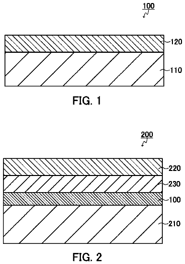
FIG. 1 is a view schematically illustrating an example of a multilayer structure according to the present invention.
FIG. 2 a view schematically illustrating another example of a multilayer structure according to Comparative Example 1.
FIG. 3 is a view schematically illustrating another example of a multilayer structure according to the present invention.
FIG. 4 is a view schematically illustrating still another example of a multilayer structure according to the present invention.
FIG. 5A is a perspective view schematically illustrating an example of the form of a tabular metal particle included in the multilayer structure of the present invention and illustrates a tabular metal particle in a circular form.
FIG. 5B is a perspective view schematically illustrating an example of the form of a tabular metal particle included in the multilayer structure of the present invention and illustrates a tabular metal particle in a hexagonal form.
FIG. 6A is a cross-sectional view schematically illustrating an example of a state in which a metal particles-containing layer containing tabular metal particles is present in the multilayer structure of the present invention.
FIG. 6B is a cross-sectional view schematically illustrating a state in which a metal particles-containing layer containing tabular metal particles is present in the multilayer structure of the present invention and illustrates a view explaining an angle (θ) between the metal particles-containing layer (parallel to the plane of a substrate) containing tabular metal particles and the plane of tabular metal particles in a hexagonal to circular forms.
FIG. 6C is a cross-sectional view schematically illustrating a state in which a metal particles-containing layer containing tabular metal particles is present in the multilayer structure of the present invention and is a view illustrating an existence region F(λ) of tabular metal particles in the depth direction of a heat ray shielding material of the metal particles-containing layer.
FIG. 7 illustrates a reflection spectrum according to Comparative Example 1.
FIG. 8 illustrates reflection spectra of multilayer structures according to Examples 1, 3, and 5.
FIG. 9 illustrates a reflection spectrum according to Example 9.
The description of the constituent elements of the present invention described below may be for some typical embodiments of the present invention, to which, however, the present invention should not be limited. In this description, the numerical range expressed by the wording “a number to another number” means the range that falls between the former number indicating the lower limit of the range and the latter number indicating the upper limit thereof.
[Multilayer Structure]
A multilayer structure of the present invention includes a metal particles-containing layer; a layer A whose refractive index is n1; and a layer B whose refractive index is n2 in order, and one of following conditions (1-1) and (2-1) is satisfied.
Condition (1-1): n1<n2 and Expression (1-1) below are satisfied. λ/4+ mλ/ 2< n 1× d 1<λ/2+ mλ/ 2 Expression (1-1)
In Expression (1-1), m represents an integer of 0 or greater; λ represents a wavelength (unit: nm) intended to prevent reflection; n1 represents a refractive index of the layer A; and d1 represents a thickness (unit: nm) of the layer A.
Condition (2-1): n1>n2 and Expression (2-1) below are satisfied. 0+ mλ/ 2< n 1× d 1<λ/4+ mλ/ 2 Expression (2-1)
In Expression (2-1), m represents an integer of 0 or greater; λ represents a wavelength (unit: nm) intended to prevent reflection; n1 represents a refractive index of the layer A; and d1 represents a thickness (unit: nm) of the layer A.
<Optical Characteristics>
By employing such a configuration, the multilayer structure of the present invention can suppress reflected light at a wavelength λ intended to prevent reflection. Although not adhering to any theories, it is predicted that optical phase rotation of light reflection of the metal particles-containing layer becomes −90° from the results of optical simulation using an FDTD method and Examples described below. The phase rotation angle is different from 0° occurring in a dielectric (interface with a substance having a low refractive index) or from 180° (interface with a substance having a high refractive index). For this reason, it is considered that reflected light at a wavelength λ intended to prevent reflection of a metal particles-containing layer for the first time can be suppressed by controlling the film thickness so as to satisfy the conditions specific to the metal particles-containing layer.
The wavelength λ intended to prevent reflection is not particularly limited, and examples thereof include respective bandwidths of visible light, infrared light, and UV light. Among these, visible light is preferable and the wavelength λ intended to prevent reflection in the multilayer structure of the present invention is preferably in the range of 380 nm to 780 nm, more preferably in the range of 400 nm to 700 nm, particularly preferably in the range of 450 nm to 650 nm, and most preferably in the range of 500 nm to 630 nm. Since the reflected light of the metal particles-containing layer in visible light leads to glare in appearance or deterioration of visible light transmittance, it is preferable to prevent reflection in the above-described range.
In a case of a structure interposed between a PET film and normal glass, the visible light reflectance of the multilayer structure of the present invention is preferably less than 15.0%, more preferably 10.3% or less, particularly preferably 10% or less, more particularly preferably 9.5% or less, and still more particularly preferably 9% or less. However, in a case of using a high refractive index substrate or glass, the total visible light reflectance is not limited thereto.
Further, the visible light transmittance, the visible light reflectance, and solar reflectance in the present specification are values defined based on JIS A5759.
In the multilayer structure of the present invention, the minimum value of the reflection spectrum is present preferably in a region of visible light having a wavelength of 380 nm to 780 nm, more preferably in the range of 400 nm to 700 nm, particularly preferably in the range of 450 nm to 650 nm, and most preferably in the range of 500 nm to 630 nm.
In the multilayer structure of the present invention, in a case of the reflection spectrum in the range of 380 nm to 1500 nm, the minimum value of the reflection spectrum is present preferably in the range of 380 nm to 780 nm and particularly preferably in the range of 400 nm to 700 nm.
The haze of the multilayer structure of the present invention is preferably 5% or less from viewpoints of improvement of the appearance and the visibility, more preferably 2% or less, particularly preferably 1.5% or less from a viewpoint of easily obtaining effects of the present invention by reducing the visible light scattering amount derived from the metal particles-containing layer and making optical interference occur easily, more particularly preferably 1.4% or less, still more particularly preferably 1.35% or less, and most preferably 1.3% or less. Further, when the haze is more than 20%, it is unfavorable for safety since the material may cause trouble in seeing outside objects when used, for example, for glass for automobiles or glass for buildings.
It is preferable that the maximum value of the solar reflectance of the multilayer structure of the present invention is present in the range of 600 nm to 2000 nm (preferably in the range of 800 nm to 1800 nm) in terms of increasing the efficiency of solar reflectance. The solar reflectance of the multilayer structure of the present invention is preferably 10% or more, more preferably 15% or more, and particularly preferably more than 15.3%.
The visible light reflectance of the multilayer structure of the present invention is preferably 60% or more from a viewpoint of easily obtaining effects of the present invention by reducing the visible light scattering amount derived from the metal particles-containing layer and making optical interference occur easily, more preferably 65% or more, and particularly preferably 70% or more. Further, when the visible light reflectance is less than 60%, the material may cause trouble in seeing outside objects when used, for example, for glass for automobiles or glass for buildings.
The UV transmittance of the multilayer structure of the present invention is preferably 5% or less and more preferably 2% or less. When the UV transmittance exceeds 5%, the color of the tabular metal particle layer is changed due to UV rays of sunlight in some cases.
<Layer Configuration/Form>
The multilayer structure of the present invention may include other layers in addition to the layer A and the layer B. For example, an embodiment having other layers such as an adhesive layer, a UV absorbent layer, a support (substrate), and a metal oxide particles-containing layer according to the necessity is also preferable.
Hereinafter, the layer structure and a preferred embodiment of the form of the multilayer structure of the present invention will be described with reference to the accompanying drawings.
(Configuration of FIG. 1 )
As the layer structure of the multilayer structure, as illustrated in FIG. 1 , an embodiment which includes a metal particles-containing layer 2 containing at least one kind of metal particle, includes a layer A whose refractive index is n1 as an undercoat layer 5 , includes a layer B whose refractive index is n2 as a support 1 , and satisfies the condition (1-1) or the condition (2-1) can be exemplified.
Condition (1-1): n1<n2 and Expression (1-1) below are satisfied. λ/4+ mλ/ 2< n 1× d 1<λ/2+ mλ/ 2 Expression (1-1)
In Expression (1-1), m represents an integer of 0 or greater; λ represents a wavelength (unit: nm) intended to prevent reflection; n1 represents a refractive index of the layer A; and d1 represents a thickness (unit: nm) of the layer A.
Condition (2-1): n1>n2 and Expression (2-1) below are satisfied. 0+ mλ/ 2< n 1× d 1<λ/4+ mλ/ 2 Expression (2-1)
In Expression (2-1), m represents an integer of 0 or greater; λ represents a wavelength (unit: nm) intended to prevent reflection; n1 represents a refractive index of the layer A; and d1 represents a thickness (unit: nm) of the layer A.
The preferred range of the condition (1-1) or the condition (2-1) will be described. Further, the following preferred range of the condition (1-1) or the condition (2-1) is the same as that of the multilayer structure of the present invention other than the configuration of FIG. 1 .
In Expressions (1-1) and (2-1) above, m represents an integer of 0 or greater and it is preferable that m represents an integer of 0 to 5 from viewpoints of low production cost and robustness of a film thickness.
Further, m is more preferably an integer of 1 to 5 from a viewpoint of capability of performing a design in which both of suppressing reflection of visible light and enhancing reflection of near-infrared light are achieved when the multilayer structure of the present invention is used as a heat ray shielding material and particularly preferably 1 from viewpoints of suppressing reflection of visible light and enhancing reflection of near-infrared light in the vicinity of 1000 nm. Further, enhancing reflection can be achieved by controlling the refractive index and the thickness of the layer B so as to satisfy Expression (4-1) described below.
Further, since the film thickness becomes extremely large and the film thickness is unlikely to be precisely controlled when m is more than 5, m is preferably 5 or less from a viewpoint of productivity.
In addition, m is preferably 0 in some cases from a viewpoint of suppressing a change in color of oblique incident light or suppressing an increase of reflected light.
In consideration of optical effects, since the effect of preventing reflection can be obtained in the range of ±λ/8, it is preferable that the variation is within this range of the film thickness. The range is more preferably in the range of ±λ/12 and most preferably in the range of ±λ/16.
In the multilayer structure of the present invention, it is preferable that one of following conditions (1-2) and (2-2) is satisfied.
Condition (1-2): n1<n2 and Expression (1-2) below are satisfied. 7λ/24+ mλ/ 2≤ n 1× d 1≤11λ/24+ mλ/ 2 Expression (1-2)
In Expression (1-2), m represents an integer of 0 or greater; λ represents a wavelength (unit: nm) intended to prevent reflection; n1 represents a refractive index of the layer A; and d1 represents a thickness (unit: nm) of the layer A.
Condition (2-2): n1>n2 and Expression (2-2) below are satisfied. 1λ/24+ mλ/ 2≤ n 1× d 1≤5λ/24+ mλ/ 2 Expression (2-2)
In Expression (2-2), m represents an integer of 0 or greater; λ represents a wavelength (unit: nm) intended to prevent reflection; n1 represents a refractive index of the layer A; and d1 represents a thickness (unit: nm) of the layer A.
Further, the preferred ranges of m in Expressions (1-2) and (2-2) above are the same as those of m in Expressions (1-1) and (2-1) above.
In the multilayer structure of the present invention, it is more preferable that one of following conditions (1-3) and (2-3) is satisfied.
Condition (1-3): n1<n2 and Expression (1-3) below are satisfied. 5λ/16+ mλ/ 2≤ n 1× d 1≤7λ/16+ mλ/ 2 Expression (1-3)
In Expression (1-3), m represents an integer of 0 or greater; λ represents a wavelength (unit: nm) intended to prevent reflection; n1 represents a refractive index of the layer A; and d1 represents a thickness (unit: nm) of the layer A.
Condition (2-3): n1>n2 and Expression (2-3) below are satisfied. 1λ/16+ mλ/ 2≤ n 1× d 1≤3λ/16+ mλ/ 2 Expression (2-3)
In Expression (2-3), m represents an integer of 0 or greater; λ represents a wavelength (unit: nm) intended to prevent reflection; n1 represents a refractive index of the layer A; and d1 represents a thickness (unit: nm) of the layer A.
Further, the preferred ranges of m in Expressions (1-3) and (2-3) above are the same as those of m in Expressions (1-1) and (2-1) above.
The layer A and the layer B in the multilayer structure of the present invention are not limited to the configuration of FIG. 1 . For example, the layer A may be another functional layer (for example, an overcoat layer as a second layer A in FIG. 3 described below) other than the undercoat layer and the layer B may be another layer (for example, an adhesive layer as a second layer B in FIG. 3 described below or a second undercoat layer in FIG. 4 described below) other than the support.
In the configuration of FIG. 1 , particularly, when the layer B is a support, it is preferable to use a support whose refractive index is 1.5 or more which is larger than that of ordinary glass whose refractive index (refractive index n is 1.5 or less) at a wavelength λ intended to prevent reflection, from viewpoints of easily adjusting the refractive index thereof to be larger than a refractive index n2 of the layer A and of being capable of using the support as the layer B by applying the refractive index of the support. In addition, in a case where the layer B is a support, it is more preferable to use a support whose refractive index is 1.55 or more and particularly preferable to use a support whose refractive index is 1.61 or more.
The preferred range of the layer B in FIG. 1 is the same as that of the layer B in FIG. 4 described below.
(Configuration of FIG. 3 )
As another preferred embodiment of the multilayer structure of the present invention, as illustrated in FIG. 3 , an embodiment which includes a metal particles-containing layer 2 containing at least one kind of metal particle, includes a layer A whose refractive index is n1 as an undercoat layer 5 , includes a layer B whose refractive index is n2 as a support 1 , includes an overcoat layer 4 as a second layer A on the opposite side of the metal particles-containing layer 2 , includes an adhesive layer 6 as a second layer B thereon, and satisfies the condition (1-1) or the condition (2-1) can be preferably exemplified. It is preferable that the second layer A and the second layer B satisfying the condition (1-1) or (2-1) are present on the opposite side of the layer A and the layer B of the metal particles-containing layer in this manner, from a viewpoint of further suppressing reflected light at a wavelength λ intended to prevent reflection.
The preferred range of the second layer A in FIG. 3 is the same as that of the condition (1-1) or (2-1).
The preferred range of the second layer B in FIG. 3 is the same as that of the layer B in FIG. 4 described below.
(Configuration of FIG. 4 )
As another preferred embodiment of the multilayer structure of the present invention, as illustrated in FIG. 4 , an embodiment which includes a layer A whose refractive index is n1 as an undercoat layer 5 , includes a layer B whose refractive index is n2 as a second undercoat layer 5 ′, includes a layer C as a support 1 , and satisfies the condition (1-1) or the condition (2-1) can be preferably exemplified.
Further, in the configuration of FIG. 4 , it is preferable that the layer B satisfies Expression (3-1) below from a viewpoint of obtaining a more excellent effect of preventing reflection. Moreover, particularly, when both of the layer A and the layer C interposing the layer B are dielectrics, it is preferable that the layer B satisfies Expression (3-1) below from a viewpoint of preventing reflection. Lλ/ 4−λ/8≤ n 2× d 2≤ Lλ/ 4+λ/8 Expression (3-1)
In Expression (3-1), L represents an integer of 1 or greater; λ represents a wavelength (unit: nm) intended to prevent reflection; n2 represents a refractive index of the layer B; and d2 represents a thickness (unit: nm) of the layer B.
The preferred range of Expression (3-1) above will be described. Further, the following preferred range of Expression (3-1) above is the same in the multilayer structure of the present invention other than the configuration of FIG. 4 .
In Expression (3-1) above, L represents an integer of 1 or greater, is preferably in the range of 1 to 5, and is more preferably 1 from viewpoints of improving productivity due to change in color of oblique incident light and the small film thickness and easily controlling the film thickness.
In consideration of optical effects, since the effect of preventing reflection can be preferably obtained in the range of ±λ/8, it is preferable that the variation is within this range of the film thickness. The range is more preferably in the range of ±λ/12 and most preferably in the range of ±λ/16.
In the multilayer structure of the present invention, it is more preferable that the layer B satisfies Expression (3-2) below. Lλ/ 4−λ/12≤ n 2× d 2≤ Lλ/ 4+λ/12 Expression (3-2)
In Expression (3-2), L represents an integer of 1 or greater; λ represents a wavelength (unit: nm) intended to prevent reflection; n2 represents a refractive index of the layer B; and d2 represents a thickness (unit: nm) of the layer B.
In the multilayer structure of the present invention, it is particularly preferable that the layer B satisfies Expression (3-3) below. Lλ/ 4−λ/16≤ n 2× d 2≤ Lλ/ 4+λ/16 Expression (3-3)
In Expression (3-3), L represents an integer of 1 or greater; λ represents a wavelength (unit: nm) intended to prevent reflection; n2 represents a refractive index of the layer B; and d2 represents a thickness (unit: nm) of the layer B.
Further, the preferred ranges of L in Expressions (3-2) and (3-3) above are the same as that of L in Expression (3-1) above.
Further, in the configuration of FIG. 4 , it is preferable that the layer B satisfies Expression (4-1) below from a viewpoint of enhancing reflection at a wavelength λ′ intended to have strong reflection. kλ′/ 4−λ/8≤ n 2× d 2≤ kλ′/ 4+λ/8 Expression (4-1)
In Expression (4-1), k represents an integer of 1 or greater; λ′ represents a wavelength (unit: nm) intended to have strong reflection; n2 represents a refractive index of the layer B; and d2 represents a thickness (unit: nm) of the layer B.
The preferred range of Expression (4-1) above will be described. Further, the following preferred range of Expression (4-1) above is the same in the multilayer structure of the present invention other than the configuration of FIG. 4 .
In Expression (4-1) above, k represents an integer of 1 or greater, is preferably in the range of 1 to 5, and is more preferably 1 from viewpoints of improving productivity due to change in color of oblique incident light and the small film thickness and easily controlling the film thickness.
The wavelength λ′ intended to have strong reflection is not particularly limited, and examples thereof include respective bandwidths of visible light, infrared light, and UV light. Among these, infrared light is preferable from a viewpoint of use as a heat ray shielding material and the wavelength λ′ intended to have reflection in the multilayer structure of the present invention is preferably in the range of 700 nm to 2500 nm, more preferably in the range of 800 nm to 1500 nm, and particularly preferably in the range of 900 nm to 1200 nm.
When the wavelength of less than 700 nm is allowed to have strong reflection, reflected light having a red color is exceedingly conspicuous, and this leads to a decrease of the transmittance of visible light. Meanwhile, since there is almost no energy at a wavelength of 2500 nm or more in the sunlight spectrum when a wavelength larger than 2500 nm is allowed to have reflection, the effect as the heat ray shielding material is decreased.
In consideration of optical effects, since the effect of preventing reflection can be preferably obtained in the range of ±λ/8, it is preferable that the variation is within this range of the film thickness. The range is more preferably in the range of ±λ/12 and most preferably in the range of ±λ/16.
The description continues in the full USPTO document.
About 6,709 words. The USPTO PDF has it with every drawing.
Fees are due 3.5, 7.5 and 11.5 years after grant. This patent expired on May 15, 2026, so the fee marked "not paid" was the one that went unpaid.
MULTILAYER STRUCTURE AND LAMINATE STRUCTURE
Filed Feb 2015 · published Jun 2015Multilayer structure and laminate structure
Filed Feb 2015 · granted May 2018Earlier publications, parents and continuations. None of them can still be enforced, or this patent would not be listed.
Prior art cited by the examiner or applicant. Useful when you check your own idea for novelty.
Everything on this page comes from the documents linked above.