 Lapsed, fee not paid4 drawings
Industrial Equipment · US 9,970,308 B2
Feather seal
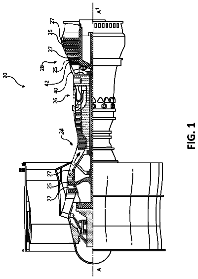
The present disclosure includes feather seals for use in gas turbine engines.
US 9,970,371 B2 · Assignee: TOYOTA JIDOSHA KABUSHIKI KAISHA · Inventors: Wakimoto; Michihiro et al.
Sheet 1 of 24 from the published document. All sheets in the USPTO PDF
A control apparatus for an internal combustion engine having a limiting current sensor includes an electronic control unit. The electronic control unit is configured to: (i) calculate a parameter relating to SOx contained in a detection subject gas using an output current of the sensor obtained when voltage reduction control is implemented to reduce an applied voltage applied to the sensor from a parameter calculation voltage; and (ii) implement the voltage reduction control when an oxygen concentration of the detection subject gas is less than a predetermined concentration or a low oxygen concentration condition, according to which an oxygen concentration of the detection subject gas is predicted to be less than a predetermined concentration, is established.
Japanese Patent Application Publication No. 2-122255 (JP 2-122255 A) describes a method and a device for measuring, in a gas containing two types of oxygen-containing gases, a relative amount of one of the oxygen-containing gases. In JP 2-122255 A, the oxygen-containing gas (water vapor or carbon dioxide, for example) in the gas is measured by controlling a voltage applied to a cell. In the field of internal combustion engines, it may be necessary to detect a concentration of sulfur oxide (SOx) in exhaust gas. It may be necessary to detect the SOx concentration of the exhaust gas more widely. Even more widely, it may be necessary to calculate a parameter (a “SOx related parameter” hereafter) relating to the SOx in the exhaust gas. The SOx related parameter is preferably calculated with a high degree of precision.
1 of 24 drawing sheets so far from the published document, cropped to the drawing. Every sheet is in the USPTO PDF.
What the patent claimed, word for word. All of it is now free to use.
This is a national phase application based on the PCT International Patent Application No. PCT/IB2014/001511 filed Aug. 13, 2014, claiming priority to Japanese Patent Application No. 2013-173210 filed Aug. 23, 2013, the entire contents of both of which are incorporated herein by reference.
The invention relates to a control apparatus and a control method for an internal combustion engine.
Japanese Patent Application Publication No. 2-122255 (JP 2-122255 A) describes a method and a device for measuring, in a gas containing two types of oxygen-containing gases, a relative amount of one of the oxygen-containing gases. In JP 2-122255 A, the oxygen-containing gas (water vapor or carbon dioxide, for example) in the gas is measured by controlling a voltage applied to a cell.
In the field of internal combustion engines, it may be necessary to detect a concentration of sulfur oxide (SOx) in exhaust gas. It may be necessary to detect the SOx concentration of the exhaust gas more widely. Even more widely, it may be necessary to calculate a parameter (a “SOx related parameter” hereafter) relating to the SOx in the exhaust gas. The SOx related parameter is preferably calculated with a high degree of precision.
The invention provides a control apparatus and a control method for an internal combustion engine, with which a parameter relating to SOx in exhaust gas is calculated with a high degree of precision.
A first aspect of the invention is a control apparatus for an internal combustion engine having a limiting current sensor, which includes an electronic control unit. The electronic control unit is configured to: (i) calculate a parameter relating to SOx contained in a detection subject gas using an output current of the sensor obtained when voltage reduction control is implemented to reduce an applied voltage applied to the sensor from a parameter calculation voltage; and (ii) implement the voltage reduction control when an oxygen concentration of the detection subject gas is less than a predetermined concentration.
A second aspect of the invention is a control apparatus for an internal combustion engine having a limiting current sensor, which includes an electronic control unit. The electronic control unit is configured to: (i) calculate a parameter relating to SOx contained in a detection subject gas using an output current of the sensor obtained when voltage reduction control is implemented to reduce an applied voltage applied to the sensor from a parameter calculation voltage; and (ii) implement the voltage reduction control when a low oxygen concentration condition, according to which an oxygen concentration of the detection subject gas is predicted to be less than a predetermined concentration, is established.
According to the configurations described above, the oxygen concentration of the detection subject gas during the voltage reduction control is low. When the oxygen concentration of the detection subject gas during the voltage reduction control is low, a small proportion of the output current obtained during the voltage reduction control is occupied by an output current generated as a result of the oxygen concentration of the detection subject gas. Accordingly, a large proportion of a value of the output current obtained during the voltage reduction control is occupied by an output current generated as a result of the amount of SOx in the detection subject gas. In other words, the output current obtained during the voltage reduction control corresponds to the amount of SOx. Therefore, the SOx related parameter can be calculated with a high degree of precision.
The oxygen concentration may include not only the oxygen concentration of the detection subject gas itself, but also a parameter that correlates with the oxygen concentration of the detection subject gas and a parameter that substantially expresses the oxygen concentration of the detection subject gas.
The low oxygen concentration condition is established when, for example, an exhaust gas recirculation (EGR) rate equals or exceeds a predetermined EGR rate, an EGR valve opening equals or exceeds a predetermined opening, an engine operating condition satisfies a high EGR operation condition, a post injection is implemented, the engine operating condition satisfies a post injection condition, exhaust addition is implemented, or the engine operating condition satisfies an exhaust addition condition.
When the engine operating condition satisfies the high EGR operation condition, the internal combustion engine is operated while controlling the EGR rate to or above the predetermined EGR rate. When the engine operating condition satisfies the post injection condition, the internal combustion engine is operated while implementing a post injection. When the engine operating condition satisfies an exhaust addition condition, the internal combustion engine is operated while implementing exhaust addition.
In the control apparatus described above, the electronic control unit may be configured to implement the voltage reduction control after controlling the oxygen concentration of the detection subject gas at or below the predetermined concentration or after establishing the low oxygen concentration condition. According to this configuration, the oxygen concentration of the detection subject gas is actively controlled at or below the predetermined concentration, and therefore calculation of the SOx related parameter can be implemented at an appropriate timing.
In the control apparatus described above, the electronic control unit may be configured to implement voltage increase control to increase the applied voltage applied to the sensor to the parameter calculation voltage before implementing the voltage reduction control, and control the oxygen concentration of the detection subject gas at or below the predetermined concentration, or establish the low oxygen concentration condition, only during implementation of the voltage reduction control. The output current resulting from the SOx is output during the voltage reduction control rather than the voltage increase control. Hence, by controlling the oxygen concentration of the detection subject gas at or below the predetermined concentration or establishing the low oxygen concentration condition only during implementation of the voltage reduction control, the SOx related parameter can be calculated with a high degree of precision by adding a minimum required amount of control.
In the control apparatus described above, the electronic control unit may be configured to warn that a fuel property is abnormal when an absolute value of the output current during the voltage reduction control equals or exceeds a warning determination value. According to this configuration, when the possibility of an abnormality in the fuel property exists, notification can be provided of the possibility of an abnormality in the fuel property. In this case, definitive calculation of the SOx related parameter is not always necessary. It may be said in this case that a parameter for determining the need to issue a warning indicating an abnormality in the fuel property is calculated as the SOx related parameter.
In the control apparatus described above, the electronic control unit may be configured to implement voltage increase control to increase the applied voltage applied to the sensor to the parameter calculation voltage before implementing the voltage reduction control and when a temperature of the sensor is less than a predetermined upper limit temperature. According to this configuration, the sensor temperature during the voltage increase control is low. When the sensor temperature during the voltage increase control is low, SOx (in particular, a sulfur component) that adheres to the sensor during the voltage increase control is less likely to separate from the sensor (or at least separation of the SOx adhered to the sensor from the sensor is suppressed), and therefore the output current of the sensor during the voltage reduction control implemented after the voltage increase control corresponds to the amount of SOx. As a result, the SOx related parameter can be calculated with an even higher degree of precision.
In the control apparatus described above, the electronic control unit may be configured to employ a parameter calculated when the oxygen concentration of the detection subject gas is lowest, from among a plurality of calculated parameters, as a final parameter relating to SOx. The output current obtained during the voltage reduction control corresponds steadily more closely to the amount of SOx as the oxygen concentration of the exhaust gas decreases. Therefore, by employing a SOx related parameter calculated when the oxygen concentration of the detection subject gas is low as the final SOx related parameter, the SOx related parameter can be calculated with an even higher degree of precision. This concept is particularly useful in a case where the oxygen concentration of the detection subject gas during the voltage reduction control differs in each implementation of the voltage reduction control. In other words, this concept is particularly useful in a case where the voltage reduction control is implemented when the oxygen concentration of the detection subject gas falls at or below the predetermined concentration, rather than after actively controlling the oxygen concentration of the detection subject gas at or below the predetermined concentration.
The SOx related parameter is, for example, the SOx concentration, or a coefficient that is used to control the internal combustion engine and set in accordance with the SOx concentration.
In the control apparatus described above, the electronic control unit may be configured to implement control to eliminate sulfur poisoning from the sensor when the output current during the voltage reduction control equals or exceeds a determination value. According to this configuration, in a case where sulfur poisoning may have occurred in the sensor, the sulfur poisoning in the sensor can be eliminated. It may be said in this case that a parameter for determining the need for sulfur poisoning recovery control is calculated as the SOx related parameter.
In the control apparatus described above, the parameter calculation voltage may be a voltage that is equal to or higher than 0.8 V. According to this configuration, an output current corresponding to the amount of SOx can be output from the sensor during the voltage reduction control. As a result, the SOx related parameter can be calculated with a high degree of precision.
In the control apparatus described above, the applied voltage upon completion of the voltage reduction control may be less than 0.7 V. According to this configuration, an output current corresponding to the amount of SOx can be output from the sensor during the voltage reduction control. As a result, the SOx related parameter can be calculated with a high degree of precision.
In the control apparatus described above, the electronic control unit may be configured to apply a first voltage that is lower than the parameter calculation voltage steadily to the sensor, and detect the oxygen concentration of the detection subject gas using the output current of the sensor obtained when the first voltage is applied to the sensor. According to this configuration, the oxygen concentration of the detection subject gas can be detected.
The electronic control unit preferably uses a peak value of the output current obtained during the voltage reduction control as the output current from which to calculate the parameter. The peak value is a minimum output current (or a maximum output current) of the output currents obtained during the voltage reduction control. It may therefore be said that the peak value is an output current that corresponds with a high degree of precision to the SOx related parameter. Hence, by using the peak value as the output current from which to calculate the SOx related parameter, the SOx related parameter can be calculated with an even higher degree of precision.
A third aspect of the invention is a control method for an internal combustion engine having a limiting current sensor, including: calculating a parameter relating to SOx contained in a detection subject gas using an output current of the sensor obtained when voltage reduction control is implemented to reduce an applied voltage applied to the sensor from a parameter calculation voltage; and implementing the voltage reduction control when an oxygen concentration of the detection subject gas is less than a predetermined concentration.
A fourth aspect of the invention is a control method for an internal combustion engine having a limiting current sensor, including: calculating a parameter relating to SOx contained in a detection subject gas using an output current of the sensor obtained when voltage reduction control is implemented to reduce an applied voltage applied to the sensor from a parameter calculation voltage; and implementing the voltage reduction control when a low oxygen concentration condition, according to which an oxygen concentration of the detection subject gas is predicted to be less than a predetermined concentration, is established.
According to the configurations described above, the oxygen concentration of the detection subject gas during the voltage reduction control is low. When the oxygen concentration of the detection subject gas during the voltage reduction control is low, a small proportion of the output current obtained during the voltage reduction control is occupied by an output current generated as a result of the oxygen concentration of the detection subject gas. Accordingly, a large proportion of the value of the output current obtained during the voltage reduction control is occupied by an output current generated as a result of the amount of SOx in the detection subject gas. In other words, the output current obtained during the voltage reduction control corresponds to the amount of SOx. Therefore, the SOx related parameter (i.e. a parameter relating to SOx) can be calculated with a high degree of precision.
Features, advantages, and technical and industrial significance of exemplary embodiments of the invention will be described below with reference to the accompanying drawings, in which like numerals denote like elements, and wherein:
FIG. 1 shows a limiting current sensor (a single cell type limiting current sensor) according to an embodiment of the invention;
FIG. 2 shows an output characteristic of the limiting current sensor of FIG. 1 ;
FIG. 3 shows an output characteristic of the limiting current sensor of FIG. 1 ;
FIG. 4 shows a relationship between a SOx concentration and a peak value of an output current;
FIG. 5 shows an internal combustion engine including a SOx concentration detection apparatus having the limiting current sensor of FIG. 1 ;
FIG. 6 is a time chart showing an output current corresponding to variation in an applied voltage, according to a first embodiment;
FIGS. 7A and 7B show how the applied voltage increases and decreases during SOx concentration detection;
FIG. 8 shows the internal combustion engine that includes the SOx concentration detection apparatus having the limiting current sensor of FIG. 1 ;
FIG. 9 is a time chart showing implementation of SOx concentration detection according to the first embodiment;
FIG. 10 shows an example of a SOx concentration detection flow according to the first embodiment;
FIG. 11 is a time chart showing implementation of SOx concentration detection according to a second embodiment;
FIG. 12 shows an example of a SOx concentration detection flow according to the second embodiment;
FIG. 13 is a time chart showing implementation of SOx concentration detection according to a third embodiment;
FIG. 14 shows an example of a SOx concentration detection flow according to the third embodiment;
FIG. 15 is a time chart showing implementation of SOx concentration detection according to a fourth embodiment;
FIG. 16 shows an example of a SOx concentration detection flow according to the fourth embodiment;
FIG. 17 is a time chart showing implementation of SOx concentration detection according to a fifth embodiment;
FIG. 18 shows an example of a SOx concentration detection flow according to the fifth embodiment;
FIG. 19 is a time chart showing implementation of SOx concentration detection according to a sixth embodiment;
FIG. 20 shows an example of a SOx concentration detection flow according to the sixth embodiment;
FIG. 21 is a time chart showing implementation of SOx concentration detection according to a seventh embodiment;
FIG. 22 shows an example of a SOx concentration detection flow according to the seventh embodiment;
FIG. 23 shows an example of a SOx concentration detection flow according to the ninth embodiment;
FIG. 24 shows an example of a SOx concentration detection flow according to the tenth embodiment;
FIG. 25 shows an example of a SOx concentration/air-fuel ratio detection flow according to the eleventh embodiment; and
FIG. 26 shows an example of a circuit employed in the limiting current sensor of FIG. 1 .
A control apparatus for an internal combustion engine according to the invention will now be described with reference to the drawings. Embodiments of the invention will be described below using as an example a case in which exhaust gas discharged from the internal combustion engine is employed as a detection subject gas and a SOx concentration is employed as a SOx related parameter.
FIG. 1 shows a limiting current sensor 30 according to a first embodiment of the invention. The limiting current sensor 30 shown in FIG. 1 is a single cell type limiting current sensor. The limiting current sensor 30 shown in FIG. 1 includes a solid electrolyte layer 31 , a first alumina layer 32 A, a second alumina layer 32 B, a third alumina layer 32 C, a fourth alumina layer 32 D, a fifth alumina layer 32 E, a diffusion controlling layer 33 , a heater 34 , a sensor cell 35 , a first sensor electrode 35 A, a second sensor electrode 35 B, a sensor cell voltage source 35 C, an atmosphere introduction passage 36 , and an interior space 37 .
The solid electrolyte layer 31 is constituted by zirconia or the like, and possesses oxygen ion conductivity. The alumina layers 32 A to 32 E are constituted by alumina. The diffusion controlling layer 33 is a porous layer through which the exhaust gas can pass. In the limiting current sensor (also referred to simply as the sensor hereafter) 30 shown in FIG. 1 , the respective layers are laminated in ascending order of the fifth alumina layer 32 E, the fourth alumina layer 32 D, the third alumina layer 32 C, the solid electrolyte layer 31 , the diffusion controlling layer 33 and the second alumina layer 32 B, and the first alumina layer 32 A. The heater 34 is disposed between the fourth alumina layer 32 D and the fifth alumina layer 32 E.
The atmosphere introduction passage 36 is a space defined by the solid electrolyte layer 31 , the third alumina layer 32 C, and the fourth alumina layer 32 D such that a part thereof is open to the atmosphere. The interior space 37 is a space defined by the first alumina layer 32 A, the solid electrolyte layer 31 , the diffusion controlling layer 33 , and the second alumina layer 32 B such that a part thereof communicates with the exterior of the sensor via the diffusion controlling layer 33 .
The first sensor electrode 35 A and the second sensor electrode 35 B are constituted by platinum, a platinum group element such as rhodium, or an alloy thereof. The first sensor electrode 35 A is disposed on a wall surface on one side of the solid electrolyte layer 31 . In other words, the first sensor electrode 35 A is disposed on the wall surface of the solid electrolyte layer 31 forming the interior space 37 . The second sensor electrode 35 B is disposed on a wall surface on the other side of the solid electrolyte layer 31 . In other words, the second sensor electrode 35 B is disposed on the wall surface of the solid electrolyte layer 31 forming the atmosphere introduction passage 36 . The electrodes 35 A, 35 B and the solid electrolyte layer 31 together constitute the sensor cell 35 . The sensor 30 is configured to be capable of applying a voltage to the sensor cell 35 from the sensor cell voltage source 35 C. More specifically, the sensor 30 is configured to be capable of applying a voltage between the first sensor electrode 35 A and the second sensor electrode 35 B from the sensor cell voltage source 35 C. The first sensor electrode 35 A is a cathode side electrode, and the second sensor electrode 35 B is an anode side electrode.
When a voltage is applied to the sensor cell 35 and SOx in the interior space 37 contacts the first sensor electrode 35 A, the SOx is broken down on the first sensor electrode 35 A such that oxygen in the SOx forms oxygen ions. The oxygen ions move through the solid electrolyte layer 31 toward the second sensor electrode 35 B. At this time, a current that is commensurate with the amount of oxygen ions moving through the interior of the solid electrolyte layer 31 flows between the first sensor electrode 35 A and the second sensor electrode 35 B. When the oxygen ions reach the second sensor electrode 35 B, the oxygen ions turn into oxygen in the second sensor electrode 35 B and are discharged into the atmosphere introduction passage 36 .
FIG. 2 shows a relationship between a sensor cell applied voltage and a sensor cell output current in the limiting current sensor according to the first embodiment. The sensor cell applied voltage is the voltage applied to the sensor cell 35 by the sensor cell voltage source 35 C. The sensor cell output current is the current flowing between the first sensor electrode 35 A and the second sensor electrode 35 B. In FIG. 2 , a line indicated by A/F=12 shows variation in the sensor cell output current relative to variation in the sensor cell applied voltage when an air-fuel ratio of the exhaust gas is 12. Similarly, lines indicated by A/F=13 to A/F=18 respectively show variation in the sensor cell output current relative to variation in the sensor cell applied voltage when the air-fuel ratio of the exhaust gas is 13 to 18.
As shown in FIG. 2 , in a case where the air-fuel ratio of the exhaust gas is 18, for example, in a range where the sensor cell applied voltage is smaller than a certain value Vth, (i) an absolute value of the sensor cell output current decreases as the sensor cell applied voltage increases when the sensor cell output current takes a negative value, and (ii) the absolute value of the sensor cell output current increases as the sensor cell applied voltage increases when the sensor cell output current takes a positive value. In a fixed range where the sensor cell applied voltage equals or exceeds the certain value Vth, the sensor cell output current takes a constant value irrespective of the sensor cell applied voltage.
A similar relationship is established between the sensor cell applied voltage and the sensor cell output current when the air-fuel ratio of the exhaust gas is between 12 and 17. As is evident from FIG. 2 , at all of the detected air-fuel ratios, when a voltage at which the sensor cell output current remains constant irrespective of the sensor cell applied voltage is applied to the sensor cell 35 , the air-fuel ratio of the exhaust gas can be detected on the basis of the sensor cell output current detected at that time. In other words, the limiting current sensor 30 according to the first embodiment can be used to detect the air-fuel ratio of the exhaust gas. The air-fuel ratio of the exhaust gas is a parameter having a correlative relationship with an oxygen concentration of the exhaust gas, and therefore, it may be said that the limiting current sensor according to the first embodiment is capable in principle of detecting the oxygen concentration of the exhaust gas.
According to the researches of the inventors of the present application, it is newly found that a current corresponding to the concentration of Sox in exhaust gas is obtained from the limiting current sensor by reducing the voltage applied to the limiting current sensor from a predetermined voltage (hereinafter, “SOx concentration detection voltage”). The voltage applied to the limiting current sensor is the voltage applied to the sensor cell 35 from the sensor cell voltage source 35 C. In the following description, the output current refers to the current output from the sensor cell 35 , and the oxygen concentration of the exhaust gas remains constant at 1%.
FIG. 3 shows variation in the output current when the applied voltage is gradually increased from 0.1 V to 1.0 V and then gradually reduced from 1.0 V to 0.1 V. The abscissa in FIG. 3 shows the applied voltage, and the ordinate in FIG. 3 shows the output current.
In FIG. 3 , a dot-dash line LU 1 shows variation in the output current when the applied voltage is increased from 0.1 V to 1.0 V in a case where the exhaust gas contains SOx. A dot-dash line LD 1 in FIG. 3 shows variation in the output current when the applied voltage is reduced from 1.0 V to 0.1 V likewise in a case where the exhaust gas contains SOx.
As shown by the dot-dash line LU 1 in FIG. 3 , when the applied voltage is increased from 0.1 V to approximately 0.2 V in a case where the exhaust gas contains SOx, the output current increases rapidly to approximately 100 μA. As the applied voltage increases from approximately 0.2 V to approximately 0.6 V, the output current remains substantially constant at approximately 100 μA. When the applied voltage exceeds approximately 0.6 V, the output current starts to increase. As the applied voltage increases from approximately 0.6 V to 1.0 V, the output current increases gradually, albeit slightly, and when the applied voltage reaches 1.0 V, the output current reaches approximately 105 μA.
As shown by the dot-dash line LD 1 in FIG. 3 , when the applied voltage is gradually reduced from 1.0 V toward 0.4 V thereafter, the output current decreases gradually from approximately 105 μA, and as the applied voltage falls from approximately 0.8 V to approximately 0.7 V, the output current decreases rapidly so as to reach approximately 80 μA. As the applied voltage falls from approximately 0.7 V to 0.4 V, the output current increases rapidly, and when the applied voltage reaches 0.4 V, the output current is approximately 100 μA.
Hence, when the applied voltage is increased from 0.4 V to 0.8 V and then reduced from 0.8 V to 0.4 V in a case where the exhaust gas contains SOx, the output current decreases rapidly and then increases rapidly as the applied voltage is reduced. In other words, when the applied voltage is reduced from 0.8 V to 0.4 V, the output current exhibits variation including a minimum value (in other words, a peak value). Referring to FIG. 3 , the output current takes the peak value when the applied voltage reaches approximately 0.7 V.
In a case where the exhaust gas contains SOx, the output current over a period extending from a point at which the applied voltage rises above approximately 0.6 V to a point at which the applied voltage reaches 1.0 V is larger than the output current over the period, extending from the point at which the applied voltage rises above approximately 0.6 V to the point at which the applied voltage reaches 1.0 V in a case where the exhaust gas does not contain SOx.
According to the researches of the inventors of the present application, it is found that there is the correlation shown in FIG. 4 between the peak value of output current and the concentration of SOx at the time when the applied voltage is reduced from 0.8 V to 0.4 V as described above in a single cell type limiting current sensor. In other words, it was found that the SOx concentration of the exhaust gas increases as a difference between a reference current (i.e. the output current at a point where the applied voltage reaches 0.8 V) and the peak value increases. The single cell type limiting current sensor according to the first embodiment can be used to detect the oxygen concentration of the exhaust gas, and accordingly the air-fuel ratio of the exhaust gas. Hence, with the single cell type limiting current sensor according to the first embodiment, it is possible to calculate (detect) the SOx concentration using the aforesaid peak value by employing a sensor that can be used to detect the oxygen concentration of exhaust gas.
FIG. 5 shows an internal combustion engine including a SOx concentration detection apparatus having the limiting current sensor 30 of FIG. 1 . The internal combustion engine of FIG. 5 is a spark ignition internal combustion engine (a so-called gasoline engine). However, the invention may also be applied to a compression self-ignition internal combustion engine (a so-called diesel engine). The internal combustion engine in FIG. 5 is operated at the stoichiometric air-fuel ratio in most engine operation regions.
An internal combustion engine 50 having the limiting current sensor 30 , shown in FIG. 5 , includes a cylinder head 51 , a cylinder block 52 , a combustion chamber 53 , a fuel injection valve 54 , a spark plug 55 , a fuel pump 56 , a fuel supply pipe 57 , a piston 60 , a connecting rod 61 , a crankshaft 62 , a crank angle sensor 63 , an intake valve 70 , an intake port 71 , an intake manifold 72 , a surge tank 73 , a throttle valve 74 , an intake pipe 75 , an air flow meter 76 , an air filter 77 , an exhaust valve 80 , an exhaust port 81 , an exhaust manifold 82 , an exhaust pipe 83 , an electronic control unit (ECU) 90 , an accelerator pedal 101 , and an accelerator pedal depression amount sensor 102 .
The fuel injection valve 54 , the spark plug 55 , the throttle valve 74 , the crank angle sensor 63 , the air flow meter 76 , the accelerator pedal depression amount sensor 102 , and the limiting current sensor 30 are electrically connected to the ECU 90 . The ECU 90 transmits signals for operating the fuel injection valve 54 , the spark plug 55 , and the throttle valve 74 thereto. The ECU 90 receives signals from the crank angle sensor 63 , the air flow meter 76 , and the accelerator pedal depression amount sensor 102 . A signal corresponding to a rotation speed of the crankshaft 62 is output from the crank angle sensor 63 . The ECU 90 calculates an engine rotation speed on the basis of the signal received from the crank angle sensor 63 . A signal corresponding to a flow rate of air passing through the intake pipe 75 (or a flow rate of air taken into the combustion chamber 53 ) is output from the air flow meter 76 . The ECU 90 calculates, an intake air amount on the basis of the signal from the air flow meter 76 . A signal corresponding to a depression amount of the accelerator pedal 101 is output from the accelerator pedal depression amount sensor 102 . The ECU 90 calculates an engine load on the basis of the signal received from the accelerator pedal depression amount sensor 102 .
The limiting current sensor 30 is attached to the exhaust pipe 83 . Hence, a gas (in other words, a detection subject gas) serving as a detection subject of the limiting current sensor 30 is exhaust gas discharged from the combustion chamber 53 . The limiting current sensor 30 outputs a current corresponding to the SOx concentration of the exhaust gas arriving therein. The ECU 90 calculates the SOx concentration on the basis of the current received from the limiting current sensor 30 . A calculation method will be described in detail below.
SOx concentration detection according to the first embodiment will now be described with reference to FIG. 6 . In the first embodiment, the voltage applied to the sensor 30 is kept steady at 0.4 V (see a period up to a time T 0 in FIG. 6 ). During the SOx concentration detection according to the first embodiment, the applied voltage is, increased from 0.4 V to 0.8 V (see a period extending from the time T 0 to a time T 1 in FIG. 6 ) and then reduced from 0.8 V to 0.4 V (see a period extending from the time T 1 to a time T 2 in FIG. 6 ). At this time, the ECU calculates (detects) the SOx concentration while the applied voltage is reduced from 0.8 V to 0.4 V using the peak value of the output current input into the ECU and the reference current. The calculated SOx concentration increases steadily as the difference between the reference current and the peak value increases.
In this embodiment, when the SOx concentration is calculated using the difference (hereinafter, “current difference”) between the peak value and the reference current, a SOx concentration corresponding to a current difference is determined in advance for each current difference by experiment or the like, for example. The SOx concentrations determined in advance are stored in the ECU in the form of a map of a current difference function, and the SOx concentration is calculated by reading the SOx concentration corresponding to the current difference calculated during the SOx concentration detection from the map.
The limiting current sensor of the SOx concentration detection apparatus according to the first embodiment can be used to detect the oxygen concentration of the exhaust gas (or the air-fuel ratio of the exhaust gas). Hence, with the SOx concentration detection apparatus according to the first embodiment, the SOx concentration of the exhaust gas can be detected using a sensor that can be used to detect the oxygen concentration of exhaust gas. In other words, when the applied voltage is maintained at a constant voltage (0.4 V, for example) or the applied voltage is increased, the SOx affects the output current to a smaller degree than other components (O.sub.2 and NOx, for example). However, the inventors of this application have found that when the applied voltage is reduced from a parameter detection voltage (0.8 V, for example), the SOx affects the output current to a greater degree than the other components. Therefore, with the SOx concentration detection apparatus according to the first embodiment, the SOx concentration can be detected with a high degree of precision using a sensor that can be used to detect the oxygen concentration of exhaust gas.
The peak value is an output current, from among output currents obtained as the applied voltage is reduced, that differs most greatly from an output current obtained when the SOx concentration is zero. It may therefore be said that the peak value is an output current that corresponds to the SOx concentration with a high degree, of precision. Hence, by employing the peak value as the output current used to detect the SOx concentration, the SOx concentration can be detected with an even higher degree of precision.
In the first embodiment, the voltage applied to the sensor before starting to reduce the applied voltage is 0.4 V. This voltage is lower than the applied voltage of 0.8 V at the start of applied voltage reduction. According to the first embodiment, therefore, an amount of power consumed during the SOx concentration detection can be reduced in comparison with a case where the voltage applied to the sensor before the start of applied voltage reduction is 0.8 V.
Oxygen concentration control according to the first embodiment will now be described. In the following description, voltage increase control is control executed during the SOx concentration detection to increase the voltage applied to the sensor from 0.4 V to 0.8 V. Further, voltage reduction control is control executed during the SOx concentration detection to reduce the voltage applied to the sensor from 0.8 V to 0.4 V.
In the SOx concentration detection according to the first embodiment, when the SOx concentration detection is requested, or in other words when implementation of the voltage increase control is requested, the voltage increase control is implemented while implementing oxygen concentration control. Oxygen concentration control is control for controlling the oxygen concentration of the exhaust gas at or below a predetermined concentration.
The predetermined concentration of the oxygen concentration of the exhaust gas is an oxygen concentration of the exhaust gas at which a proportion of an oxygen output current is much smaller than a proportion of a SOx output current, for example zero (or substantially zero). The proportion of the oxygen output current is a proportion of the output current obtained during the voltage reduction control that is occupied by an output current generated as a result of the oxygen in the exhaust gas. The proportion of the SOx output current is a proportion of the output current obtained during the voltage reduction control that is occupied by an output current generated as a result of the SOx in the exhaust gas.
For example, the oxygen concentration control is control for increasing an EGR rate by increasing an EGR valve opening, or control for implementing a post injection, or control for implementing exhaust addition in an internal combustion engine shown in FIG. 8 .
In the internal combustion engine shown in FIG. 8 , an exhaust gas purification catalyst 85 that purifies components of the exhaust gas is attached to an exhaust pipe 83 . The exhaust gas purification catalyst 85 has at least an oxidation capacity. A fuel addition valve 84 that adds fuel to the exhaust gas flowing through, the exhaust pipe 83 is attached to the exhaust pipe 83 upstream of the exhaust gas purification catalyst 85 . The fuel addition valve 84 is electrically connected to the ECU 90 . The ECU 90 controls an operation of the fuel addition valve 84 . The control for implementing exhaust addition is control for adding fuel to the exhaust gas from the fuel addition valve 84 . The fuel added to the exhaust gas reacts with the oxygen in the exhaust gas due to the oxidation capacity of the exhaust gas purification catalyst 85 , and is thereby burned. As a result, the oxygen in the exhaust gas is consumed such that the oxygen concentration of the exhaust gas decreases.
In the internal combustion engine shown in FIG. 8 , the sensor 30 is attached to the exhaust pipe 83 downstream of the exhaust gas purification catalyst 85 . However, when the fuel added to the exhaust gas from the fuel addition valve 84 reacts with the oxygen in the exhaust gas so as to burn regardless of the oxidation capacity of the exhaust gas purification catalyst 85 , the sensor 30 may be attached to the exhaust pipe 83 upstream of the exhaust gas purification catalyst 85 .
The SOx concentration detection according to the first embodiment will now be described with reference to FIG. 9 . In the following description, a SOx concentration detection request flag is set when the SOx concentration detection is requested, and reset when the SOx concentration detection is completed.
The description continues in the full USPTO document.
About 6,525 words. The USPTO PDF has it with every drawing.
Fees are due 3.5, 7.5 and 11.5 years after grant. This patent expired on May 15, 2026, so the fee marked "not paid" was the one that went unpaid.
CONTROL APPARATUS AND CONTROL METHOD FOR INTERNAL COMBUSTION ENGINE
Filed Aug 2014 · published Jul 2016Control apparatus and control method for internal combustion engine
Filed Aug 2014 · granted May 2018Earlier publications, parents and continuations. None of them can still be enforced, or this patent would not be listed.
Prior art cited by the examiner or applicant. Useful when you check your own idea for novelty.
Everything on this page comes from the documents linked above.