The entire disclosure of Japanese Patent Application No. 2015-094139 filed on May 1, 2015 including description, claims, drawings, and abstract are incorporated herein by reference in its entirety.
Background of the invention
Field of the Invention
The present invention relates to a sheet conveying technique, and more particularly, to a purging technique.
Description of the Related Art
In general, a sheet conveying device mounted on an image forming apparatus such as a printer and a copying machine continuously conveys a plurality of sheets along one route. A printing process or the like is sequentially performed on these sheets at a high speed of several tens to several hundred or more of ppm.
When a jam (a paper jam) occurs at a certain position on the route, the image forming apparatus interrupts the process and causes a user to remove the jammed sheet. At this time, different sheets located before and after the jammed sheet are also forcedly stopped on the route. In order to resume the process, these sheets also need to be removed from the route in principle. However, the user feels troublesome whenever removing these sheets.
Among the sheet conveying devices of the related art, there is known a sheet conveying device devised for a user who feels troublesome in the sheet removing operation. Here, when the image forming apparatus interrupts the printing process or the like due to the jam or the like, all movable sheets are automatically discharged from the route. The sheet discharging operation which is performed by the sheet conveying device along with the process interrupting operation in the image forming apparatus will be referred to as a “purging operation”. Generally, the sheet as a purging target is discharged to a dedicated tray provided separately from a normal sheet discharging tray.
Patent Literature 1:
Jp 2014-119634 a
Since some space is needed for the installation of a purging tray, the image forming apparatus having the purging function is limited to a comparatively large-sized image forming apparatus so far. However, there is a demand for providing the purging function even in a medium-sized image forming apparatus used in an office or the like in accordance with the recent trend of the high functionality of the image forming apparatus.
Meanwhile, when the purging tray is provided in the medium-sized image forming apparatus, it is difficult to meet a decrease in size and cost strongly required in the medium-sized image forming apparatus.
As the medium-sized image forming apparatus used for an office, for example, an image forming system having a duplex printing function illustrated in FIG. 20 is known.
An image forming system 950 illustrated in FIG. 20 includes an image forming apparatus 900 , a relay device 910 , and a post-processing device 920 . The image forming apparatus 900 is a color copying machine having a duplex printing function. In the duplex printing mode, the image forming system 950 performs the following operation.
First, Y, M, C, and K colors of toner images formed by an imaging part 901 are transferred in multiple layers onto an intermediate transfer belt 906 traveling in the circumferential direction as indicated by the arrow. The color toner images which are transferred onto the intermediate transfer belt 906 in multiple layers are secondarily transferred onto a front surface of a sheet SHT fed from a cassette 902 at a secondary transfer position 907 .
When the sheet SHT having the toner images secondarily transferred thereonto passes through a fixing part 903 , the toner image is fixed onto the front surface of the sheet SHT and the sheet SHT is guided to a reversing part 904 through a branch point 960 .
The reversing part 904 reversely rotates the reversing roller 941 immediately before the tail end of the sheet SHT reaches the reversing roller 941 while the leading end of the sheet SHT is caused to protrude outward from the reversing port 940 provided in the casing by the reversing roller 941 . Accordingly, the conveying direction of the sheet SHT is switched back (reversed). The reversed sheet SHT is guided to a circulation part 905 .
The sheet SHT which is guided to the circulation part 905 is conveyed along a circulation path 951 and is returned to the secondary transfer position 907 . During the circulating and conveying operation, a toner image forming operation is performed by the imaging part 901 . Thus, when the sheet SHT passes through the secondary transfer position 907 , the toner image on the intermediate transfer belt 906 is secondarily transferred onto the rear surface of the sheet SHT.
When the sheet SHT having the toner image secondarily transferred thereonto passes through the fixing part 903 , the toner image is fixed onto the rear surface of the sheet SHT and the sheet SHT is conveyed from the branch point 960 to the post-processing device 920 through the relay device 910 . In the post-processing device 920 , post-processing such as a staple-binding process is performed on the sheet SHT and the post-processed sheet SHT is discharged.
By a sheet reversing mechanism having such a reversing port 940 , a space necessary for switching back the sheet SHT is saved. Thus, if the outside of the reversing port 940 can be also used as a purging destination, a purging function can be provided in the image forming apparatus 900 while the casing of the image forming apparatus 900 is maintained in a small size.
As the purging function, for example, a function is considered in which sheets SH 1 to SH 3 are forcedly discharged to the outside of the apparatus from the reversing port 940 when the sheets SH 1 to SH 3 are conveyed inside the image forming apparatus 900 in the case where a jam occurs in a sheet SH 0 of the post-processing device 920 .
Incidentally, when the sheets SH 1 to SH 3 are continuously conveyed and the purging operation is performed while the sheets are guided to the reversing port 940 in an original conveying order, for example, an order of SH 1 , SH 2 , and SH 3 , there is a case in which a new jam occurs due to the collision of the sheet SH 1 conveyed toward the reversing port 940 during the reversing operation of the sheet SH 3 in accordance with the positions of the sheets SH 1 to SH 3 on the conveying route in the event of the jam (as indicated by the dashed line). In this case, the effort of the user in the sheet removing operation is not reduced.
Such a problem can generally occur in a sheet conveying device having the above-described reversing mechanism in addition to the sheet conveying device provided in the image forming apparatus.
Summary of the invention
The present invention has been made in view of the above-described problems, and an object thereof is to provide a sheet conveying device including a reversing mechanism, conveying a sheet so that a part of the sheet protrudes outward from a reversing port and reversing the sheet, and having a purging function capable of reducing the effort of a user in a sheet removing operation as much as possible and to provide an image forming apparatus and an image forming system including the sheet conveying device.
To achieve the abovementioned object, according to an aspect, a sheet conveying device configured to convey a sheet toward a device at a sheet conveying destination in a normal operation state and to interrupt the sheet conveying operation toward the device at the sheet conveying destination when a jam is detected, the sheet conveying device reflecting one aspect of the present invention comprises: a conveying unit configured to convey a sheet along a conveying path; a switching unit configured to switch a sheet conveying destination from a branch point as a downstream end of the conveying path to any one of a delivery path extending toward the device at the sheet conveying destination and a reversing port formed as an opening of a casing of the sheet conveying device so that a space outside the casing is used as a space for reversing the sheet conveying direction; a delivering unit configured to deliver the sheet on the delivery path toward the device at the sheet conveying destination; a reversing unit configured to first convey the sheet from the reversing port toward the outside of the casing to a position in which a part of the sheet protrudes and deliver the sheet from the position toward a circulation path while reversing the conveying direction of the sheet; a circulating unit configured to convey the sheet delivered toward the circulation path along the circulation path and return the sheet to the conveying path while the sheet is reversed; and a control unit configured to control the reversing unit so that a first sheet is not reversed and is purged from the reversing port toward the outside of the casing if there is the first sheet supposed to be reversed by the reversing unit while being conveyed toward the reversing port when a jammed sheet is detected in the device at the sheet conveying destination.
Further, when there is a second sheet conveyed in any one of the conveying unit and the circulating unit separately from the first sheet at the jam detection time point, the control unit preferably controls the conveying unit, the reversing unit, the circulating unit, and the switching unit so that the sheet conveying destination of each second sheet is switched to the reversing port and each second sheet is purged from the reversing port toward the outside of the casing while not reversing the second sheet after the first sheet is purged.
Furthermore, if a predetermined condition is satisfied when the first sheet does not exist and a third sheet currently reversed by the reversing unit exists at the jam detection time point, the control unit preferably stops the reversing operation of the third sheet and re-reverses the third sheet in a direction toward the reversing port so that the third sheet is purged from the reversing port toward the outside of the casing.
Here, when there is a second sheet conveyed in at least one of the conveying unit and the circulating unit separately from the third sheet at the jam detection time point, the control unit preferably controls the conveying unit, the reversing unit, the circulating unit, and the switching unit so that the sheet conveying destination of each second sheet is switched to the reversing port and each second sheet is purged from the reversing port toward the outside of the casing while not reversing the second sheet after the third sheet is purged.
Here, on the assumption that the third sheet is re-reversed while the second sheet reaching the branch point at the first time is continuously conveyed after the jam detection time point, the predetermined condition is preferably a condition in which a leading end of the second sheet in the sheet conveying direction reaches the reversing unit after the reversing operation of the third sheet is completely switched to the re-reversing operation thereof.
Further, on the assumption that the third sheet is re-reversed while the second sheet reaching the branch point at the first time is continuously conveyed after the jam detection time point, the predetermined condition is preferably a condition in which the second sheet does not contact the third sheet.
Furthermore, the conveying speed of the third sheet during the re-reversing operation is preferably faster than the conveying speed of the third sheet during the reversing operation of the reversing unit.
Further, the circulating unit preferably includes a pair of rotating and conveying members conveying the sheet along the circulation path while nipping the sheet during the reversing operation, the reversing unit and the pair of rotating and conveying members are preferably driven by different driving mechanisms, and when a leading end of the third sheet in the sheet conveying direction during the reversing operation reaches the pair of rotating and conveying members at the jam detection time point, the control unit preferably stops each sheet conveying operation by prohibiting the purging operation regardless of whether the predetermined condition is satisfied.
Here, the driving mechanism of the rotating and conveying member is not preferably provided with a member stopping the transmission of a driving force to the rotating and conveying member at the jam detection time point so as to connect or disconnect a transmission route transmitting the driving force to the rotating and conveying member.
Further, the circulating unit preferably includes a pair of rotating and conveying members conveying the sheet along the circulation path while nipping the sheet during the reversing operation, the reversing unit and the pair of rotating and conveying members are preferably driven by different driving mechanisms, the driving mechanism of the rotating and conveying member is preferably provided with a member stopping the transmission of a driving force to the rotating and conveying member at the jam detection time point so as to connect or disconnect a transmission route transmitting the driving force to the rotating and conveying member, and if the predetermined condition is satisfied even when a leading end of the third sheet in the sheet conveying direction during the reversing operation reaches the pair of rotating and conveying member at the jam detection time point, the control unit preferably disconnects the transmission route and purges the third sheet.
Here, the circulating unit preferably includes a plurality of the pairs of rotating and conveying members provided in the circulation path with a gap therebetween, and on the assumption that the pair of rotating and conveying members closest to the sheet conveying direction of the sheet reversed from the reversing unit among the plurality of the pairs of rotating and conveying members is set as a first pair of rotating and conveying members and the pair of rotating and conveying members secondly closest to the sheet conveying direction of the reversed sheet is set as a second pair of rotating and conveying members, the control unit preferably purges the third sheet if the predetermined condition is satisfied when the leading end of the third sheet in the sheet conveying direction reaches the first pair of rotating and conveying members and does not reach the second pair of rotating and conveying members and the control unit preferably stops each sheet conveying operation by prohibiting the purging operation even if the predetermined condition is satisfied when the leading end of the third sheet in the sheet conveying direction reaches the second pair of rotating and conveying members.
Further, the control unit preferably stops each sheet conveying operation by prohibiting the purging operation regardless of whether the predetermined condition is satisfied when the third sheet is a predetermined type of sheet.
Here, the predetermined type of sheet is preferably a thick sheet having a basis weight larger than a predetermined value or any one of a high-quality sheet, a glossy sheet, a coated sheet, and a color sheet.
Further, if a condition is not satisfied in which a leading end of the second sheet in the sheet conveying direction reaches the branch point before the switching unit completely switches the sheet conveying destination from the delivery path to the reversing port on the assumption that the second sheet reaching the branch point at the first time is continuously conveyed, the control unit preferably prohibits the purging operation of the second sheet and retracts the second sheet to the delivery path while setting the sheet conveying destination as the delivery path, and if there is the second sheet reaching the branch point at the next time, the control unit preferably causes the switching unit to switch the sheet conveying destination from the delivery path to the reversing port and purges the second sheet.
Furthermore, the control unit preferably stops each sheet conveying operation by prohibiting the purging operation when the first sheet is a specific type of sheet.
Here, the specific type of sheet is preferably a thin sheet having a basis weight smaller than a predetermined value.
To achieve the abovementioned object, according to an aspect, an image forming apparatus configured to form an image on a sheet conveyed by a sheet conveying part, the image forming apparatus reflecting one aspect of the present invention comprises the sheet conveying device as the sheet conveying part.
To achieve the abovementioned object, according to an aspect, an image forming system reflecting one aspect of the present invention comprises: the image forming apparatus; and a post-processing device configured to perform predetermined post-processing on a sheet having an image formed thereon by the image forming apparatus, and a device at a sheet conveying destination of the sheet conveying device of the image forming apparatus is the post-processing device.
Brief description of the drawings
The above and other objects, advantages and features of the present invention will become more fully understood from the detailed description given hereinbelow and the appended drawings which are given by way of illustration only, and thus are not intended as a definition of the limits of the present invention, and wherein:
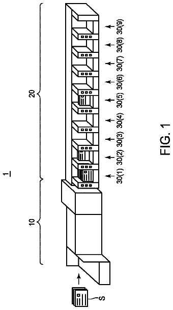
FIG. 1 is a perspective view illustrating the appearance of an image forming system;
FIG. 2 is a front view schematically illustrating the inner structure of the image forming system;
FIG. 3 is a schematic diagram illustrating a sheet conveying route which is formed by a conveying part of the image forming system;
FIGS. 4A to 4D are schematic diagrams gradually illustrating a state where a sheet group is conveyed on the route in a duplex printing mode;
FIG. 5 is a block diagram illustrating the configuration of an electronic control system of a MFP;
FIGS. 6A to 6D are schematic diagrams illustrating the positions of the sheets conveyed inside a printer at a time point in which a jam is detected by a post-processing device;
FIG. 7 is a schematic diagram illustrating a branch point BP and positions Ps and Pt defined on the conveying route;
FIGS. 8A to 8C are schematic diagrams illustrating an example of the flow of the sheet in a purging control when a second condition is satisfied;
FIG. 9A is a diagram illustrating an example of a timing chart when a normal rotation of a reversing motor is changed to a reverse rotation thereof (when a re-reversing operation is not performed) and FIG. 9B is a diagram illustrating an example of a timing chart when the normal rotation of the reversing motor is changed to the reverse rotation thereof or the reverse rotation of the reversing motor is changed to the normal rotation thereof (when the re-reversing operation is performed);
FIG. 10 is a flowchart illustrating an example of the content of a sheet conveying control in a duplex printing mode;
FIG. 11 is a flowchart illustrating the content of a sub-routine of a purging control;
FIG. 12 is a flowchart illustrating the content of a sub-routine of a first control;
FIG. 13 is a flowchart illustrating the content of a sub-routine of a second control;
FIG. 14 is a flowchart illustrating the content of a sub-routine of a third control;
FIG. 15 is a flowchart illustrating the content of a second control according to a modified example;
FIG. 16 is a flowchart illustrating a part of the content of another second control according to the modified example;
FIG. 17 is a flowchart illustrating a part of the content of a second control including a sheet re-reversing operation prohibiting process according to the modified example;
FIG. 18 is a flowchart illustrating a part of the content including a sheet re-reversing operation determining process in response to the type of sheet in the second control according to the modified example;
FIG. 19 is a flowchart illustrating a part of the content including a sheet re-reversing operation determining process in response to a sheet leading end advancing state for a sheet being reversed at a jam detection time point in the second control according to the modified example; and
FIG. 20 is a diagram illustrating the schematic configuration of an image forming system of the related art.
Description of the preferred embodiments
Hereinafter, embodiments of a sheet conveying device, and an image forming apparatus and an image forming system including the sheet conveying device according to the present invention will be described with reference to the drawings. However, the scope of the invention is not limited to the illustrated examples.
[Appearance of Image Forming System]
FIG. 1 is a perspective view illustrating the appearance of an image forming system according to the embodiment of the present invention. The image forming system includes an MFP (Multi-Function Peripheral) 100 , a relay unit 140 , and a post-processing device 150 .
The MFP 100 has the functions of a scanner, a color copying machine, and a color laser printer. As illustrated in FIG. 1 , an ADF (Auto Document Feeder) 110 is attached to an upper surface of a casing of the MFP 100 so as to be openable and closable. A scanner 120 is built in the upper part of the casing located directly below the ADF 110 , and a printer 130 is built in the lower part of the casing. A sheet feeding cassette 133 is attached to the bottom part of the printer 130 so as to be drawable.
The MFP 100 is of a sheet ejection type. That is, a sheet discharging tray 46 is separably installed in a gap DSP between the scanner 120 and the printer 130 , and receives the sheet discharged from a sheet discharging port 42 at the back side of the gap DSP. At the gap DSP, a reversing tray 47 is provided on the sheet discharging tray 46 . In a duplex printing mode, a sheet having an image printed on a front surface (a first surface) is switched back (reversed) on the reversing tray 47 . That is, the sheet is first conveyed from a reversing port 44 opened above the sheet discharging port 42 to the upward protruding position of the reversing tray 47 and then is drawn into the reversing port 44 again while the conveying direction is reversed.
The relay unit 140 is assembled to a casing part of the MFP 100 instead of the sheet discharging tray 46 . The relay unit 140 receives the sheet from the sheet discharging port 42 and relays the sheet to a post-processing device 150 .
The post-processing device 150 performs post-processing on a sheet bundle received from the sheet discharging port 42 through the relay unit 140 in response to the instruction from the MFP 100 . The post-processing includes, for example, a process of evenly arranging the sheet bundle and a process of stapling the sheet bundle.
As illustrated in FIG. 1 , the post-processing device 150 includes two sheet discharging trays 151 and 152 . The upper tray 151 has the sheets stacked thereon in a state where the sheets are delivered from the sheet discharging port 42 . The lower tray 152 has the sheets stacked thereon in a state where the sheet bundle is evenly arranged or stapled.
[Inner Structure of Image Forming System]
FIG. 2 is a front view schematically illustrating the inner structures of the systems 100 , 140 , and 150 illustrated in FIG. 1 . In FIG. 2 , these inner components are depicted as if the casing is transparent. As illustrated in FIG. 2 , the printer 130 includes a feeding part 10 , an imaging part 20 , a fixing part 30 , and a delivering part 40 . An image forming unit of the MFP 100 is realized by the combination of these components and a toner image is formed on the sheet based on image data.
The feeding part 10 feeds a sheet SH 1 one by one to the imaging part 20 from a sheet bundle SHT stacked on a sheet feeding cassette 11 or a hand insertion tray 16 by the use of feeding roller groups 12 P, 12 R, 12 F, 13 , 14 , and 15 .
An example of the size of the sheet SHT received in the sheet feeding cassette 11 and the hand insertion tray 16 includes A3, A4, A5, or B4. Further, the sheet feeding cassette 11 is able to receive a normal sheet therein and the hand insertion tray 16 is able to receive, for example, a thin sheet in addition to the normal sheet. As the normal sheet, a sheet of which the basis weight is within a predetermined range, for example, 60 to 100 g/m.sup.2 can be used. Then, as the thin sheet, a sheet of which the basis weight is smaller than a predetermined value, for example, 60 g/m.sup.2 can be used.
The imaging part 20 forms a toner image on a sheet SH 2 fed from the feeding part 10 . Specifically, four imaging units 21 Y, 21 M, 21 C, and 21 K respectively first expose the surfaces of photosensitive drums 25 Y, 25 M, 25 C, and 25 K according to a pattern based on image data by using a laser beam emitted from an exposure part 26 and form electrostatic latent images on the surfaces thereof.
Next, the imaging units 21 Y, 21 M, 21 C, and 21 K develop the electrostatic latent images by the toner of yellow (Y), magenta (M), cyan (C), and black (K). The four color toner images are sequentially transferred onto the same position on the surface of an intermediate transfer belt 23 in a superimposed state from the surfaces of the photosensitive drums 25 Y, 25 M, 25 C, and 25 K by the electric field formed between each of the primary transfer rollers 22 Y, 22 M, 22 C, and 22 K and each of the photosensitive drums 25 Y, 25 M, 25 C, and 25 K. In this way, one color toner image is formed at the position.
The color toner image passes through a nip between the intermediate transfer belt 23 and the secondary transfer roller 24 along with the sheet SH 2 fed from the feeding part 10 so that the color toner image is transferred onto the front surface of the sheet SH 2 by the electric field formed between the intermediate transfer belt 23 and the secondary transfer roller 24 . Subsequently, the secondary transfer roller 24 delivers the sheet SH 2 toward the fixing part 30 .
The fixing part 30 heat-fixes the toner image onto the sheet SH 2 delivered from the imaging part 20 . Specifically, when the sheet SH 2 passes through a nip between a fixing roller 31 and a pressing roller 32 , the fixing roller 31 applies heat of a heater provided therein to the front surface of the sheet SH 2 and the pressing roller 32 presses the heating portion of the sheet SH 2 against the fixing roller 31 . Due to the heat of the fixing roller 31 and the pressure of the pressing roller 32 , the toner image is fixed onto the front surface of the sheet SH 2 . Subsequently, a front sheet discharging roller 33 delivers the sheet SH 2 toward the delivering part 40 .
The delivering part 40 delivers the sheet SH 2 delivered from the front sheet discharging roller 33 toward the relay unit 140 or reverses the sheet SH 2 by the reversing tray 47 . As illustrated in FIG. 2 , the delivering part 40 includes a switching claw 41 , the sheet discharging port 42 , a sheet discharging roller 43 , the reversing port 44 , a reversing roller 45 , and a circulation path 48 . As for the rollers including the sheet discharging roller 43 , a pair of rotation members rotates while the sheet is nipped therebetween so that the sheet is conveyed by a rotation force, but in the description below, the pair of rollers will be simply referred to as the roller.
The switching claw 41 is a claw-shaped or plate-shaped member of which a base end is rotatably fixed between the sheet discharging port 42 and the reversing port 44 and moves a front end thereof upward and downward while swinging about the base end. When the sheet delivered by the front sheet discharging roller 33 is delivered toward the relay unit 140 , the switching claw 41 moves the front end upward so as to form a path (hereinafter, referred to as a “delivery path”) toward the sheet discharging port 42 . Then, when the sheet is reversed by the reversing port 44 , the switching claw 41 moves the front end downward so as to form a path (hereinafter, referred to as a “reversing path”) toward the reversing port 44 . Each of the sheet discharging port 42 and the reversing port 44 is formed as a thin and elongated slit which is opened in the horizontal direction in the casing of the MFP 100 facing the gap DSP. The reversing port 44 corresponds to an opening of the casing so that an external space of the casing of the MFP 100 is used as a space for reversing the sheet conveying direction.
The sheet discharging roller 43 is disposed at the inside of the sheet discharging port 42 and rotates so as to deliver a sheet SH 3 moved along the switching claw 41 from the sheet discharging port 42 toward the relay unit 140 by the peripheral surface. The reversing roller 45 is disposed at the inside of the reversing port 44 and is rotatable in both the normal and reverse rotation directions.
The reversing roller 45 first delivers a sheet SH 4 moved along the switching claw 41 by the peripheral surface while rotating in the normal rotation direction from the reversing port 44 so that the sheet SH 4 is placed on the reversing tray 47 . The reversing roller 45 rotates reversely immediately before the tail end of the sheet SH 4 passes therethrough so that the sheet SH 4 is drawn from the reversing tray 47 into the reversing port 44 , that is, the sheet SH 4 is fed toward the circulation path 48 while the conveying direction is reversed.
In the circulation path 48 , conveying rollers 48 a to 48 d return a sheet SH 5 delivered by the reversing roller 45 toward the conveying route inside the feeding part 10 while the sheet is reversed. Here, the rotation direction in which each of the conveying rollers 48 a to 48 d conveys the sheet SH 5 will be referred to as the normal rotation direction.
Subsequently, the feeding part 10 feeds the sheet SH 5 to the imaging part 20 again and the imaging part 20 forms a toner image on a rear surface (a second surface) of the sheet SH 5 . The fixing part 30 performs a heat treatment on the sheet SH 5 again and the delivering part 40 delivers the sheet SH 5 toward the relay unit 140 at this time.
The relay unit 140 relays the sheet delivered from the sheet discharging port 42 toward the post-processing device 150 by the use of conveying roller groups 141 , 142 , and 143 .
The post-processing device 150 includes an entrance conveying roller 161 , a branch claw 162 , an upper sheet discharging roller 163 , a conveying roller group 164 , a reversing roller 165 , a post-processing part 166 , and a lower sheet discharging roller 167 in addition to the sheet discharging trays 151 and 152 .
The entrance conveying roller 161 receives a sheet from the relay unit 140 and draws the sheet into the casing. The branch claw 162 is a claw-shaped or plate-shaped member of which a base end is rotatably fixed and moves a front end thereof upward and downward while swinging about the base end. When the sheet drawn by the entrance conveying roller 161 is delivered toward the upper sheet discharging roller 163 , the branch claw 162 moves the front end downward so as to form a path toward the upper sheet discharging roller 163 . Meanwhile, when the sheet is delivered toward the post-processing part 166 , the branch claw moves the front end upward so as to form a path toward the conveying roller group 164 .
The upper sheet discharging roller 163 is disposed near the base end of the upper sheet discharging tray 151 and discharges the sheet moved from the entrance conveying roller 161 along the branch claw 162 toward the upper sheet discharging tray 151 . The conveying roller group 164 conveys the sheet moved from the entrance conveying roller 161 along the branch claw 162 to the reversing roller 165 in a direction toward the post-processing part 166 .
The reversing roller 165 is disposed at the entrance of the post-processing part 166 and is rotatable in both the normal and reverse rotation directions. The reversing roller 165 first feeds the sheet delivered from the conveying roller group 164 toward the post-processing part 166 by the peripheral surface while rotating in the normal rotation direction. Next, the reversing roller 165 draws the sheet bundle subjected to the post-processing by the peripheral surface from the post-processing part 166 while rotating in the reverse rotation direction.
The post-processing part 166 performs post-processing including an arranging process and a stapling process on a bundle as a predetermined number of sheets fed from the reversing roller 165 . The lower sheet discharging roller 167 is disposed near the base end of the lower sheet discharging tray 152 and discharges the sheet bundle drawn from the post-processing part 166 by the reversing roller 165 toward the lower sheet discharging tray 152 .
[Sheet Conveying Part]
As illustrated in FIG. 2 , in the MFP 100 , a part of the imaging part 20 and the fixing part 30 including a driving roller 23 R of the intermediate transfer belt 23 , the secondary transfer roller 24 , the fixing roller 31 , the pressing roller 32 , the front sheet discharging roller 33 , and the like serve as a sheet conveying part other than the feeding part 10 and the delivering part 40 .
FIG. 3 is a schematic diagram illustrating a sheet conveying route formed by the sheet conveying part.
As illustrated in FIG. 3 , the route is formed as below. First, three sheet feeding routes extending from the sheet feeding cassettes 11 a and 11 b and the hand insertion tray 16 are combined into one route (hereinafter, referred to as a “conveying path”) 1 a at a first merging point MP 1 . The conveying path 1 a passes through the imaging part 20 and the fixing part 30 and is divided into two routes, that is, a delivery path 4 a and a reversing path 4 b at a branch point BP facing the switching claw 41 of the delivering part 40 .
The delivery path 4 a is connected to the conveying route inside the relay unit 140 through the sheet discharging port 42 , and the reversing path 4 b is connected to the circulation path 48 by the reversing port 44 . The circulation path 48 is connected to the conveying path 1 a at a second merging point MP 2 positioned near a timing roller 14 .
Referring to FIG. 3 again, a plurality of optical sensors 1FS, 2FS, CS, TS, ES, 1RS, and 2RS is provided on these conveying routes in addition to the roller group 12 P and the like illustrated in FIG. 2 . The optical sensor 1FS and the like detect the sheet passing through the installation positions.
Specifically, each optical sensor includes a light emitting part and a light receiving part. The light emitting part emits a predetermined wavelength of light such as an infrared ray and the light receiving part detects the light of the wavelength. While one sheet passes through the installation position of each optical sensor, the sheet interrupts the light emitted from the light emitting part at the front side of the light receiving part or reflects the light toward the light receiving part. Since the output of the light receiving part changes in response to the interruption or the reflection of the emitted light, the sheet passing through the installation position of each optical sensor is detected. The detection result is transmitted from the feeding part 10 , the delivering part 40 , and the like to a main control unit 60 to be described later (see FIG. 5 ). In response to the detection result, the main control unit 60 determines whether the sheet conveying operation is normally performed without any jam or the sheet conveying timing is abnormal due to a jam as will be described below.
Sheet feeding sensors 1FS and 2FS are provided at the start end of the conveying route illustrated in FIG. 3 , that is, the vicinity of the sheet feeding cassettes 11 a and 11 b . In response to the existence of the delay of the sheet passage timing indicated by the output, it is determined whether the feeding roller groups 12 P, 12 F, and 12 R feed the sheets to the route at a normal timing.
In the route from the second sheet feeding cassette 11 b , a longitudinal conveying sensor CS is provided at the front side of the first merging point MP 1 in addition to a longitudinal conveying roller 13 . In response to the existence of the delay of the sheet passage timing indicated by the output, it is determined whether the longitudinal conveying roller 13 delivers the sheets toward the first merging point MP 1 at a normal timing.
In addition to the timing roller 14 , a timing sensor TS is provided at the downstream side of any one of the first merging point MP 1 and the second merging point MP 2 in the vicinity of the boundary between the feeding part 10 and the imaging part 20 . The timing roller 14 is generally stopped and also first stops the sheet moved from any one of the sheet feeding cassettes 11 a and 11 b , the hand insertion tray 16 , and the circulation path 48 . The timing roller 14 further starts to rotate at a timing indicated by the driving signal output from the main control unit 60 so as to deliver the stopped sheet toward the imaging part 20 at that timing.
In response to the existence of the delay of the sheet passage timing indicated by the output of the timing sensor TS, it is determined whether the sheet reaches the timing roller 14 at a normal timing or the sheet is delivered from the timing roller 14 at a normal timing. Further, the size of the sheet can be measured from the time necessary for the timing roller 14 to deliver each sheet.
A sheet discharging sensor ES is provided at the upstream side of the branch point BP. In response to the existence of the delay of the sheet passage timing indicated by the output, it is determined whether the front sheet discharging roller 33 delivers a sheet at a normal timing or the sheet discharging roller 43 or the reversing roller 45 draws a sheet at a normal timing.
The circulation path 48 is provided with conveying sensors 1RS and 2RS. In response to the existence of the delay of the sheet passage timing indicated by the output, it is determined whether the conveying rollers 48 a to 48 d of the circulation path 48 convey a sheet at a normal timing.
Although not illustrated in FIG. 3 , a plurality of optical sensors is also provided in the conveying routes of the relay unit 140 and the post-processing device 150 . The post-processing device 150 detects the position of the sheet being conveyed on the route by using these sensors and transmits the detection result to the main control unit 60 of the MFP 100 . Based on the detection result, it is determined whether the conveying timing is abnormal and a conveying error such as a jam occurs on the conveying routes of the relay unit 140 and the post-processing device 150 .
When the jam occurring in the current conveyed sheet is detected, a current printing job or the like is interrupted. A user can solve the jam by opening or closing an outer cover (not illustrated) for the MFP 100 , the relay unit 140 , and the post-processing device 150 and manually removing the sheet stopped on the conveying route due to the jam. When the jam is solved, the interrupted job is resumed.
Referring to FIG. 3 , driving motor groups M 1 to M 12 , TM, MM, FM, SM, and RM of the roller group 12 P and the like and driving solenoids SL 1 and SL 2 of the switching claw 41 and the branch claw 162 are provided in the periphery of the conveying route. Each of the motor M 1 and the like is, for example, a DC brushless (BLDC) motor and is generally rotatable in both the normal and reverse rotation directions. Each of the motor M 1 and the like applies a rotation force to a roller as a driving target through a transmission system including a gear, a belt, and the like. The solenoids SL 1 and SL 2 move movable iron cores (plunger) in the axial direction by using an electromagnet and press and pull the switching claw 41 and the branch claw 162 so as to swing the claws upward and downward.
The description continues in the full USPTO document.
 Lapsed, fee not paid11 drawings