Cross reference to related applications
This application claims the benefit of priority of Japanese application no. 2015-203772, filed on Oct. 15, 2015, which is incorporated herein by reference.
Background of the invention
Field of the Invention
The present invention relates to a tire-holding device including a shaft body and a support body which supports the shaft body. A bladder for expanding in a tire to hold the tire is fixed to the shaft body, and the support body supports the shaft body.
Description of the Related Art
Conventionally, as a mechanism for holding a tire, there is known a tire-holding device including a shaping unit including a shaft body to which a bladder is fixed, and a fluid supply unit for supplying fluid into the bladder (e.g., JP-A-2007-98803). If the fluid supply unit supplies fluid into the bladder, the bladder expands in the tire and holds the tire.
The shaping unit includes a fluid port for supplying fluid into the bladder. To supply fluid into the bladder through the fluid port, it is necessary to precisely position the shaft body in a circumferential direction of the tire-holding device so that the fluid port is located at a predetermined position.
Summary of the invention
Hence, in view of the above-described circumstances, it is an object of the present invention to provide a tire-holding device which does not need to precisely position a shaft body in a circumferential direction of the tire-holding device.
There is provided a tire-holding device including:
a shaft body having a portion thereof inserted into a bladder which is fixed to the shaft body, the bladder expanding in a tire to hold the tire; and
a support body which comes into contact with the shaft body to support the shaft body, wherein
the shaft body includes an inner hole placed inside the bladder, and an outer hole placed outside the bladder and is brought into communication with the inner hole, and
the support body includes a support hole, and when the support body supports the shaft body, the outer hole and the support hole come into communication with each other irrespective of a position of the shaft body in its circumferential direction.
Also, the tire-holding device may have a configuration in which:
the support body includes an end surface support portion which supports an end surface of the shaft body,
the outer hole is placed in a position on an axis of the shaft body in the end surface of the shaft body, and
when the support body supports the shaft body, the support hole is placed at a position on the axis of the shaft body in the end surface support portion so that the support hole comes into communication with the outer hole irrespective of a position of the shaft body in the circumferential direction.
Also, the tire-holding device may have a configuration in which:
the support body includes an end surface support portion which supports an end surface of the shaft body,
the outer hole is placed at a position deviated from an axis of the shaft body in the end surface of the shaft body,
the support hole is placed at a position deviated from the axis of the shaft body in the end surface support portion, and
when the support body supports the shaft body, at least one of the outer hole and the support hole extends around an axis of the shaft body such that the outer hole and the support hole come into communication with each other irrespective of a position of the shaft body in the circumferential direction.
Also, the tire-holding device may have a configuration in which:
the support body includes a peripheral surface support portion which supports a peripheral surface of the shaft body,
the outer hole is placed in the peripheral surface of the shaft body,
the support hole is placed in the peripheral surface support portion, and
when the support body supports the shaft body, at least one of the outer hole and the support hole extends around the axis of the shaft body such that the outer hole and the support hole come into communication with each other irrespective of a position of the shaft body in its circumferential direction.
Also, the tire-holding device may have a configuration in which:
the shaft body is provided therein with a valve which opens and closes between the inner hold and the outer hole,
the valve includes a movable valve body, a valve seat placed closer to the outer hole than the valve body, and a projecting portion which projects from the valve body and which can move with respect to the valve seat together with the valve body, and
the projecting portion passes through the valve seat and extends toward the outer hole, and when the valve body comes into contact with the valve seat, the projecting portion projects from the end surface.
Also, the tire-holding device may have a configuration in which:
the shaft body is provided therein with a valve which opens and closes between the inner hold and the outer hole,
the valve includes a movable valve body, and a valve seat placed closer to the outer hole than the valve body,
the support body includes a projecting portion which projects from the end surface support portion, and
a length of the projecting portion is set in such a manner that when the support body supports the shaft body, the projecting portion passes through the outer hole and the valve seat to press the valve body.
Also, the tire-holding device may have a configuration in which:
the valve includes an elastic body which biases the valve body toward the valve seat.
As described above, this tire-holding device exerts an excellent effect that it is unnecessary to precisely position the shaft body in the circumferential direction.
Brief description of the drawings
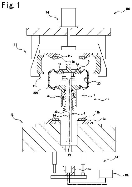
FIG. 1 is a schematic sectional view of an entire tire-vulcanizing device having a tire-holding device according to an embodiment;
FIG. 2 is a sectional view of an entire tire-holding unit according to the embodiment, and shows a movable state;
FIG. 3 is an enlarged view of essential portions in FIG. 2 ;
FIG. 4 is a sectional view of the entire tire-holding unit according to the embodiment, and shows a fixed state;
FIG. 5 is an enlarged view of essential portions in FIG. 4 ;
FIG. 6 is a front view of an entire inner cylindrical body according to the embodiment;
FIG. 7 is a sectional view of an entire assembly having an outer cylindrical body according to the embodiment;
FIG. 8 is a bottom view of an entire shaft body according to the embodiment;
FIG. 9 shows essential portions of the shaft body according to the embodiment, and is an enlarged sectional view taken along line IX-IX in FIG. 8 ;
FIG. 10 is a plan view of an entire support body according to the embodiment;
FIG. 11 is a sectional view of the entire support body according to the embodiment, and is a sectional view taken along line XI-XI in FIG. 10 ;
FIG. 12 is a diagram for describing an operation of the tire-holding device according to the embodiment, and is a vertical sectional view of essential portions of the tire-holding unit;
FIG. 13 is a diagram for describing the operation of the tire-holding device according to the embodiment, and is a vertical sectional view of essential portions of the shaft body and the support body;
FIG. 14 is a diagram for describing the operation of the tire-holding device according to the embodiment, and is a vertical sectional view of essential portions of the tire-holding unit;
FIG. 15 is a diagram for describing the operation of the tire-holding device according to the embodiment, and is a vertical sectional view of essential portions of the shaft body and the support body;
FIG. 16 is a diagram for describing an operation of the tire-holding device according to the embodiment, and is a vertical sectional view of essential portions of the shaft body and the support body;
FIG. 17 is a diagram for describing the operation of the tire-holding device according to the embodiment, and is a vertical sectional view of essential portions of the shaft body and the support body;
FIG. 18 is a side view of essential portions of a shaft body according to another embodiment;
FIG. 19 is a side view of an entire shaft body according to the other embodiment;
FIG. 20 is a vertical sectional view of an entire support body according to the other embodiment;
FIG. 21 is a sectional view of the entire support body according to the other embodiment, and is a sectional view taken along line XXI-XXIX in FIG. 20 ;
FIG. 22 is a diagram for describing an operation of the tire-holding device according to the other embodiment, and is a vertical sectional view of essential portions of the shaft body and the support body;
FIG. 23 is a diagram for describing an operation of a tire-holding device according to another embodiment, and is a vertical sectional view of essential portions of a shaft body and a support body; and
FIG. 24 is a diagram for describing an operation of the tire-holding device according to the other embodiment, and is a vertical sectional view of essential portions of the shaft body and the support body.
Detailed description of the preferred embodiments
An embodiment of a tire-holding device will be described with reference to FIGS. 1 to 17 . In the drawings ( FIGS. 18 to 24 are also the same), sizes of the drawings do not absolutely match with actual sizes.
As shown in FIG. 1 , the tire-vulcanizing device 100 according to an embodiment includes an upper container 11 placed at an upper location, a lower container 12 placed at a lower location, and a drive device 13 for driving an upper container 11 . The tire-vulcanizing device 100 includes a tire-holding device 10 for holding the tire 200 .
The upper container 11 includes a side mold 11 a which forms a sidewall portion of the tire 200 , a plurality of tread molds 11 b which form a tread portion of the tire 200 , and a bead ring 11 c into which a bead portion of the tire 200 is fitted. The lower container 12 includes a side mold 12 a which forms a sidewall portion of the tire 200 , and a bead ring 12 b into which a bead portion of the tire 200 is fitted.
When the molds are to be opened, the drive device 13 separates the pair of side molds 11 a and 12 a from each other, and the drive device 13 moves the plurality of annularly arranged tread molds 11 b outward so that the tread molds 11 b radially spread. According to this, it is possible to bring the tire 200 in and out.
When the molds are to be closed, the drive device 13 moves the tread molds 11 b inward and brings the side molds 11 a and 12 a close to each other so that the tread molds 11 b gather and forma continuously connected annular shape. According to this, inner surfaces of the molds 11 a , 11 b and 12 a can come into intimate contact with an outer surface of the tire 200 .
The tire-holding device 10 includes a tire-holding unit 14 for holding the tire 200 , and a fluid device 15 for flowing fluid into and out from a tire-holding unit 14 . The tire-holding unit 14 is attachable to and detachable from the lower container 12 .
The tire-holding unit 14 includes a cylindrical bladder 1 which expands in the tire 200 to hold the tire 200 , and a shaft body 2 . A portion of the shaft body 2 is inserted into the bladder 1 . The tire-holding unit 14 includes a fixing body 3 which fixes the bladder 1 and the shaft body 2 to each other, and a connecting body 4 which connects the bladder 1 and the shaft body 2 to each other.
The fluid device 15 includes a support body 8 which comes into contact with the shaft body 2 to support the same when the tire-holding unit 14 is attached to the lower container 12 . The fluid device 15 includes a fluid source 15 a through which fluid flows into the bladder 1 and through which fluid flows out from the bladder 1 . The fluid device 15 also includes first and second flow paths 15 b and 15 c which are paths for fluid between the support body 8 and the fluid source 15 a . Examples of the fluid are vapor and inert gas such as nitrogen and helium.
As shown in FIG. 2 , the bladder 1 is formed into a cylindrical shape, and includes a first opening 1 a and a second opening 1 b . In the embodiment, the bladder 1 is made of elastic material such as rubber.
The fixing body 3 includes a bladder-fixing portion 31 for fixing the second opening 20 b of the bladder 1 , and a closing portion 32 for closing the second opening 1 b of the bladder 1 to restrain fluid from flowing out from the second opening 1 b of the bladder 1 . The closing portion 32 is formed into a disk shape, and the bladder-fixing portion 31 is connected to an outer periphery of the closing portion 32 .
The closing portion 32 is immovably fixed to a second end 2 b on the other side of the shaft body 2 . According to this, the fixing body 3 is immovably fixed to the second end 2 b on the other side of the shaft body 2 , and the fixing body 3 fixes the bladder 1 and the shaft body 2 to each other. The second opening 1 b of the bladder 1 can be attached to and detached from the bladder-fixing portion 31 .
As shown in FIGS. 2 to 5 , the connecting body 4 includes a bladder-fixing portion 41 for fixing the first opening 1 a of the bladder 1 , and a closing portion 42 for closing the first opening 1 a of the bladder 1 to restrain fluid from flowing out from the first opening 1 a of the bladder 1 . The connecting body 4 includes a switching mechanism 5 which switches between a fixed state where the connecting body 4 is fixed to the shaft body 2 and a movable state where the connecting body 4 can move relative to the shaft body 2 in the axial direction.
The closing portion 42 is formed into an annular disk shape, and the bladder-fixing portion 41 is connected to an outer periphery of the closing portion 42 . The shaft body 2 is inserted into a hole of the closing portion 42 . The closing portion 42 is switched by the switching mechanism 5 between a fixed state where the closing portion 42 is fixed to the shaft body 2 and a movable state where the closing portion 42 can move relative to the shaft body 2 in the axial direction. The first opening 1 a of the bladder 1 can be attached to and detached from the bladder-fixing portion 41 .
The switching mechanism 5 includes a cylindrical inner cylindrical body 51 into which the shaft body 2 is inserted, a cylindrical outer cylindrical body 52 into which the inner cylindrical body 51 is inserted, and a biasing body 53 which biases the inner cylindrical body 51 and the outer cylindrical body 52 . The outer cylindrical body 52 is fixed to the bladder 1 . Specifically, the outer cylindrical body 52 is connected to the bladder-fixing portion 41 and the closing portion 42 on the other side (on the side of second end 2 b of shaft body 2 ) in the axial direction.
As shown in FIGS. 2 to 7 , the inner cylindrical body 51 is provided at its other side in the axial direction with an inner cylindrical taper portion 51 a . A diameter of an outer periphery of the inner cylindrical taper portion 51 a is increased toward one side (toward first end 2 a of shaft body 2 ) in the axial direction. The inner cylindrical body 51 is provided at the one side in the axial direction with an exposed portion 51 b which projects from the outer cylindrical body 52 .
The outer cylindrical body 52 is provided at its other side in the axial direction with an outer cylindrical taper portion 52 a . A diameter of an inner periphery of the outer cylindrical taper portion 52 a is increased toward one side in the axial direction. The outer cylindrical body 52 is provided at its one side in the axial direction with a convex portion 52 b which projects inward in the radial direction.
The outer cylindrical taper portion 52 a is superposed on the inner cylindrical taper portion 51 a in the axial direction. Therefore, if the outer cylindrical body 52 moves toward one side in the axial direction relative to the inner cylindrical body 51 , the inner periphery of the outer cylindrical taper portion 52 a comes into contact with the outer periphery of the inner cylindrical taper portion 51 a.
The inner cylindrical taper portion 51 a includes an elastic portion 51 c . When an outer periphery of the inner cylindrical taper portion 51 a comes into contact with an inner periphery of the outer cylindrical taper portion 52 a , the elastic portion 51 c elastically deforms. More specifically, the inner cylindrical taper portion 51 a includes a cylindrical base portion 51 d , and a plurality of elastic pieces 51 e which project from the base portion 51 d toward the other side in the axial direction and which are arranged along the circumferential direction.
The inner cylindrical taper portion 51 a is provided at its inner periphery with a pressured contact portion 51 f which pressurizes and comes into contact with a peripheral surface 28 of the shaft body 2 . If the elastic portion 51 c elastically deforms, the pressured contact portion 51 f approaches the outer periphery of the shaft body 2 and pressurizes and comes into contact with the peripheral surface 28 of the shaft body 2 . In the embodiment, the inner cylindrical body 51 and the outer cylindrical body 52 are made of metal such as stainless steel, for example. Only the pressured contact portion 51 f of the inner cylindrical body 51 may be made of material which is different from those of other portions. For example, the contact portion 51 f may be made of material having a higher friction coefficient than the shaft body 2 .
In the embodiment, the biasing body 53 is a cylindrical coil spring. The inner cylindrical body 51 is inserted into the biasing body 53 . The biasing body 53 is placed between the inner cylindrical taper portion 51 a of the inner cylindrical body 51 and the convex portion 52 b of the outer cylindrical body 52 . The biasing body 53 biases the inner cylindrical body 51 and the outer cylindrical body 52 , thereby stabilizing them. According to this, the axial direction of the inner cylindrical body 51 and the axial direction of the outer cylindrical body 52 match with each other.
As shown in FIGS. 2 and 3 , when the connecting body 4 is in the movable state, the biasing body 53 elastically deforms such that it shrinks and by this restoring force, the biasing body 53 biases the outer cylindrical body 52 such that the outer cylindrical body 52 moves toward the one side in the axial direction relative to the inner cylindrical body 51 . Further, as shown in FIGS. 4 and 5 , also when the connecting body 4 is in the fixed state, the biasing body 53 elastically deforms such that it shrinks and by this restoring force, the biasing body 53 biases the outer cylindrical body 52 in such a direction that the outer cylindrical body 52 moves toward the one side in the axial direction relative to the inner cylindrical body 51 .
As shown in FIGS. 2 and 4 , the shaft body 2 includes first and second inner holes 21 and 22 placed in the bladder 1 , and first and second outer holes 23 and 24 placed outside the bladder 1 . The shaft body 2 includes a first communicating unit 25 which brings the first inner hole 21 and the first outer hole 23 into communication with each other, and a second communicating unit 26 which brings the second inner hole 22 and the second outer hole 24 into communication with each other.
The shaft body 2 is provided therein with a first valve 6 which opens and closes between the first inner hole 21 and the first outer hole 23 , and a second valve 7 which opens and closes between the second inner hole 22 and the second outer hole 24 . When the tire-holding unit 14 is attached to the lower container 12 , an end surface 27 and a peripheral surface 28 of the support body 8 on the side of a first end 2 a are supported by the support body 8 .
Of the shaft body 2 , an outer shape of a cross section of a portion of the shaft body 2 connected to the connecting body 4 and an outer shape of a cross section of a portion of the shaft body 2 supported by the support body 8 which intersect with an axial direction of the shaft body 2 at right angles are the same along the axial direction. In this embodiment, the portions of the shaft body 2 are formed into columnar shapes, and the outer shape of the cross section of these portions is circular having the same diameters along the axial direction.
The first and second inner holes 21 and 22 are placed between the fixing body 3 and the connecting body 4 so that they are placed in the bladder 1 . In the embodiment, in the shaft body 2 , fluid flows into the bladder 1 from the first inner hole 21 , and fluid in the bladder 1 flows out from the second inner hole 22 .
As shown in FIGS. 8 and 9 , the first outer hole 23 is formed into circular. The first outer hole 23 is placed at a portion in the shaft body 2 supported by the support body 8 . Specifically, the first outer hole 23 is placed on an axis of the end surface 27 of the shaft body 2 .
The second outer hole 24 is formed into circular. The second outer hole 24 is placed on a portion of the shaft body 2 supported by the support body 8 . Specifically, the second outer hole 24 is placed at a position deviated from an axis of the end surface 27 of the shaft body 2 .
The first valve 6 includes a movable first valve body 61 , a first valve seat 62 placed closer to the first outer hole 23 than the first valve body 61 , and a first elastic body 63 which biases the first valve body 61 toward the first valve seat 62 so that the first valve body 61 comes into contact with the first valve seat 62 . In a state where the first valve 6 is in its closed state, it closes between the first inner hole 21 and the first outer hole 23 , and in its opened state, the first valve 6 opens between the first inner hole 21 and the first outer hole 23 .
The first valve seat 62 includes the contact portion 62 a which comes into contact with the first valve body 61 , and a first valve hole 62 b which is in communication with the first outer hole 23 and is closed when the first valve body 61 comes into contact with the first contact portion 62 a . The first contact portion 62 a is formed annularly, and the first valve hole 62 b is placed at a central portion of the first contact portion 62 a.
In this embodiment, the first valve body 61 is formed into a spherical shape. The first elastic body 63 always elastically deforms, and biases the first valve body 61 toward the first valve seat 62 . In this embodiment, the first elastic body 63 is a coil spring.
Therefore, when the first valve body 61 comes into contact with the first valve seat 62 , the first valve 6 is closed, and if the first valve body 61 separates from the first valve seat 62 , the first valve 6 opens. When fluid which flows in from the first outer hole 23 biases the first valve body 61 against a biasing force of the first elastic body 63 or internal pressure of the bladder 1 , it is possible to switch the first valve 6 from the closed state to the opened state.
The second valve 7 includes a movable second valve body 71 , a second valve seat 72 placed closer to the second outer hole 24 than the second valve body 71 , and a second elastic body 73 which biases the second valve body 71 toward the second valve seat 72 so that the second valve body 71 comes into contact with the second valve seat 72 . The second valve 7 includes a projecting portion 74 which projects from the second valve body 71 . When the second valve 7 is closed, it closes between the second inner hole 22 and the second outer hole 24 , and when the second valve 7 opens, it opens between the second inner hole 22 and the second outer hole 24 .
The second valve seat 72 includes a second contact portion 72 a which is in contact with the second valve body 71 , and a second valve hole 72 b which is in communication with the second outer hole 24 and is closed when the second valve body 71 comes into contact with the second contact portion 72 a . The second contact portion 72 a is formed annularly, and the second valve hole 72 b is placed at a central portion on the second contact portion 72 a.
In this embodiment, the second valve body 71 is formed into a spherical shape. The second elastic body 73 always elastically deforms, and the second elastic body 73 biases the second valve body 71 toward the second valve seat 72 . In this embodiment, the second elastic body 73 is a coil spring.
The projecting portion 74 passes through the second valve seat 72 (specifically, second valve hole 72 b ), and extends toward the second outer hole 24 . In this embodiment, the projecting portion 74 is formed long. When the second valve body 71 comes into contact with the second valve seat 72 , the projecting portion 74 projects from the end surface 27 of the shaft body 2 . The projecting portion 74 is integrally formed together with the second valve body 71 . The projecting portion 74 is movable with respect to the second valve seat 72 together with the second valve body 71 .
Therefore, if the second valve body 71 comes into contact with the second valve seat 72 , the second valve 7 is closed, and if the second valve body 71 separates from the second valve seat 72 , the second valve 7 opens. If the projecting portion 74 is pressed toward the interior of the shaft body 2 against the biasing force of the second elastic body 73 and the internal pressure of the bladder 1 , the second valve 7 can be switched from its closed state to its opened state.
As shown in FIGS. 10 and 11 , the support body 8 includes an end surface support portion 81 which supports the end surface 27 of the shaft body 2 , and a peripheral surface support portion 82 which supports the peripheral surface 28 of the shaft body 2 . The support body 8 supports the shaft body 2 such that a position of the axis of the shaft body 2 becomes constant irrespective of a position of the shaft body 2 in its circumferential direction (i.e., irrespective of position of second outer hole 24 in the shaft body 2 ).
The support body 8 includes a first support hole 83 which comes into communication with the first outer hole 23 when the support body 8 supports the shaft body 2 . The support body 8 includes a second support hole 84 which comes into communication with the second outer hole 24 when the support body 8 supports the shaft body 2 .
The first support hole 83 is formed circular. The first support hole 83 is placed in the end surface support portion 81 . The first support hole 83 is placed on the axis of the shaft body 2 with respect to the shaft body 2 which is supported by the support body 8 . According to this, the first support hole 83 is brought into communication with the first outer hole 23 when the support body 8 supports the shaft body 2 irrespective of a circumferential position of the shaft body 2 .
The second support hole 84 is formed in the end surface support portion 81 . The second support hole 84 is placed at a position deviated from the axis of the shaft body 2 with respect to the shaft body 2 supported by the support body 8 . Specifically, the second support hole 84 extends around the axis of the shaft body 2 with respect to the shaft body 2 supported by the support body 8 . In this embodiment, the second support hole 84 is formed into a continuous annular shape. According to this, the second support hole 84 is in communication with the second outer hole 24 when the support body 8 supports the shaft body 2 irrespective of a circumferential position of the shaft body 2 .
A configuration of the tire-holding device 10 according to the embodiment will be described below. Next, the operation of the tire-holding device 10 of the embodiment will be described with reference to FIGS. 12 to 17 .
First, the tire-holding unit 14 is detached from the lower container 12 , and is placed outside the tire-vulcanizing device 100 . As shown in FIG. 12 , in a movable state where an elastic portion 51 c of the inner cylindrical body 51 restores (not elastically deformed), the connecting body 4 can move in the axial direction with respect to the shaft body 2 . Therefore, the connecting body 4 is placed at a predetermined position in accordance with the tire 200 to be held.
In a state where the inner cylindrical body 51 and the shaft body 2 are held, a fluid supply device 300 supplies fluid from the first outer hole 23 as shown in FIG. 13 . At this time, by biasing the first valve body 61 by fluid against a biasing force of the first elastic body 63 and the internal pressure of the bladder 1 , the first valve 6 is switched from the closed state to the opened state. According to this, fluid flows into the bladder 1 through the first outer hole 23 , the first valve 6 , the first communicating unit 25 and the first inner hole 21 .
According to this, as shown in FIG. 14 , as the bladder 1 swells, the outer cylindrical body 52 moves toward one side (lower side in FIG. 14 ) in the axial direction with respect to the inner cylindrical body 51 . Since an inner peripheral portion of an outer tapered portion 52 a comes into contact with an outer peripheral portion of an inner tapered portion 51 a , the elastic portion 51 c elastically deforms. As a result, since the pressurizing contact portion 51 f approaches and comes into contact with a peripheral surface 28 of the shaft body 2 under pressure, the connecting body 4 is fixed to the shaft body 2 , and the shaft body 2 is switched to the fixed state.
If the bladder 1 swells until it holds the tire 200 , the fluid supply device 300 stops the supply of fluid. When the connecting body 4 is in its fixed state, a biasing body 53 biases the outer cylindrical body 52 in a direction in which the outer cylindrical body 52 moves toward one side in the axial direction with respect to the inner cylindrical body 51 . Therefore, the fixed state of the connecting body 4 is maintained unless an external force is applied to the connecting body 4 .
Since the fluid supply device 300 stops the supply of fluid, as shown in FIG. 15 , the valve bodies 61 and 71 are in contact with the valve seats 62 and 72 by the biasing forces of the elastic bodies 63 and 73 and the internal pressure of the bladder 1 . According to this, the first and second valves 6 and 7 are brought into the closed states. Therefore, since the internal pressure of the bladder 1 is maintained, it is possible to maintain the state where the tire-holding unit 14 holds the tire 200 . According to this, it is possible to transfer the tire-holding unit 14 in a state where the tire 200 is held.
Thereafter, if the tire-holding unit 14 is attached to the lower container 12 , the shaft body 2 is supported by the support body 8 as shown in FIG. 16 . Specifically, the end surface 27 of the shaft body 2 is supported by the end surface support portion 81 of the support body 8 , and the peripheral surface 28 of the shaft body 2 is supported by the peripheral surface support portion 82 of the support body 8 . According to this, an axial position of the shaft body 2 with respect to the support body 8 becomes constant irrespective of a circumferential position of the shaft body 2 with respect to the support body 8 .
At this time, since the support body 8 presses the projecting portion 74 toward an interior of the shaft body 2 against the biasing force of the second elastic body 73 and the internal pressure of the bladder 1 , the second valve body 71 separates from the second valve seat 72 . The first valve body 61 is in contact with the first valve seat 62 by the biasing force of the first elastic body 63 and the internal pressure of the bladder 1 .
The first outer hole 23 is placed at a position on the axis of the shaft body 2 , and the first support hole 83 is also placed at a position on the axis of the shaft body 2 . According to this, the first outer hole 23 and the first support hole 83 are in communication with each other irrespective of a circumferential position of the shaft body 2 with respect to the support body 8 .
The second outer hole 24 is placed in a position deviated from the axis of the shaft body 2 , and the second support hole 84 annularly extends such that it one laps around the axis of the shaft body 2 . According to this, the second outer hole 24 and the second support hole 84 are in communication with each other irrespective of a circumferential position of the shaft body 2 with respect to the support body 8 (i.e., irrespective of position of second outer hole 24 with respect to support body 8 ).
Thereafter, if fluid is supplied from the fluid source 15 a , the fluid flows into the shaft body 2 through the first flow path 15 b , the first support hole 83 and the first outer hole 23 . At this time, as shown in FIG. 17 , the fluid biases the first valve body 61 against the biasing force of the first elastic body 63 and the internal pressure of the bladder 1 . According to this, the first valve 6 is switched from the closed state to the opened state. The fluid flows into the bladder 1 through the first outer hole 23 , the first valve 6 , the first communicating unit 25 and the first inner hole 21 .
The fluid in the bladder 1 flows out from the shaft body 2 through the second inner hole 22 , the second communicating unit 26 , the second valve 7 and the second outer hole 24 . The fluid which flows out from the shaft body 2 returns to the fluid source 15 a (or is discharged from fluid source 15 a ) through the second support hole 84 and a second flow path 15 c.
When the tire-vulcanizing device 100 vulcanizes the tire 200 in this manner, the fluid flows into the bladder 1 or flows out from the bladder 1 . The fluid device 15 controls an inflow amount and an outflow amount of fluid based on the internal pressure of the bladder 1 and an amount of heat to be supplied to the tire 200 .
As described above, the tire-holding device 10 according to the embodiment includes:
a shaft body 2 having a portion thereof inserted into a bladder 1 which is fixed to the shaft body 2 , the bladder 1 expanding in a tire 200 to hold the tire 200 ; and
a support body 8 which comes into contact with the shaft body 2 to support the shaft body 2 ,
the shaft body 2 includes an inner hole 21 , 22 placed inside the bladder 1 , and an outer hole 23 , 24 placed outside the bladder 1 and is brought into communication with the inner hole 21 , 22 , and
the support body 8 includes a support hole 83 , 84 , and when the support body 8 supports the shaft body 2 , the outer hole 23 , 24 and the support hole 83 , 84 come into communication with each other irrespective of a position of the shaft body 2 in its circumferential direction.
According to this configuration, a portion of the shaft body 2 is inserted into the bladder 1 , and the bladder 1 is fixed to the shaft body 2 . The shaft body 2 includes the inner holes 21 and 22 which are placed inside the bladder 1 , and the outer holes 23 and 24 which are placed outside the bladder 1 and in communication with the inner holes 21 and 22 , and the support body 8 includes support holes 83 and 84 .
When the support body 8 comes into contact with the shaft body 2 and supports the shaft body 2 , the support holes 83 and 84 come into communication with the outer holes 23 and 24 irrespective of the circumferential position of the shaft body 2 . According to this, fluid can flow into and flow out from the bladder 1 through the support holes 83 and 84 , the outer holes 23 and 24 and the inner holes 21 and 22 . Therefore, it is unnecessary to precisely position the shaft body 2 with respect to the support body 8 in the circumferential direction.
In the tire-holding device 10 according to the embodiment,
the support body 8 includes an end surface support portion 8 which supports an end surface 27 of the shaft body 2 ,
the outer hole 23 is placed in a position on an axis of the shaft body 2 in the end surface 27 of the shaft body 2 , and
when the support body 8 supports the shaft body 2 , the support hole 83 is placed at a position on the axis of the shaft body 2 in the end surface support portion 81 so that the support hole 83 comes into communication with the outer hole 23 irrespective of a position of the shaft body 2 in the circumferential direction.
According to this configuration, the outer hole 23 is placed at a position on the axis of the shaft body 2 of the end surface 27 of the shaft body 2 . The support body 8 includes the end surface support portion 81 which supports the end surface 27 of the shaft body 2 , and the support hole 83 is placed at a position on the axis of the shaft body 2 in the end surface support portion 81 . According to this, when the support body 8 supports the shaft body 2 , the outer hole 23 and the support hole 83 can be brought into communication with each other irrespective of a circumferential position of the shaft body 2 .
In the tire-holding device 10 according to the embodiment,
the support body 8 includes an end surface support portion 8 which supports an end surface 27 of the shaft body 2 ,
the outer hole 24 is placed at a position deviated from an axis of the shaft body 2 in the end surface 27 of the shaft body 2 ,
the support hole 84 is placed at a position deviated from the axis of the shaft body 2 in the end surface support portion 81 , and
when the support body 8 supports the shaft body 2 , at least one of the outer hole 24 and the support hole 84 extends around an axis of the shaft body 2 such that the outer hole 24 and the support hole 84 come into communication with each other irrespective of a position of the shaft body 2 in the circumferential direction.
According to this configuration, the outer hole 24 is placed at a position deviated from the axis of the shaft body 2 of the end surface 27 of the shaft body 2 . The support body 8 includes the end surface support portion 81 which supports the end surface 27 of the shaft body 2 . The support hole 84 is placed at a position deviated from the axis of the shaft body 2 of the end surface support portion 81 . At least one of the outer hole 24 and the support hole 84 (support hole 84 in this embodiment) extends around the axis of the shaft body 2 . Therefore, when the support body 8 supports the shaft body 2 , the outer hole 24 and the support hole 84 can be brought into communication with each other irrespective of the circumferential position of the shaft body 2 .
In the tire-holding device 10 according to the embodiment,
the shaft body 2 is provided therein with a valve 7 which opens and closes between the inner hold 22 and the outer hole 24 ,
the valve 7 includes a movable valve body 71 , a valve seat 72 placed closer to the outer hole 24 than the valve body 71 , and a projecting portion 74 which projects from the valve body 71 and which can move with respect to the valve seat 72 together with the valve body 71 , and
the projecting portion 74 passes through the valve seat 72 and extends toward the outer hole 24 , and when the valve body 71 comes into contact with the valve seat 72 , the projecting portion 74 projects from the end surface 27 .
According to this configuration, the shaft body 2 is provided therein with the valve 7 . The valve 7 includes the movable valve body 71 , and the valve seat 72 placed closer to the outer hole 24 than the valve body 71 . If the valve body 71 comes into contact with the valve seat 72 , the valve 7 is closed, and the valve 7 closes between the inner hole 22 and the outer hole 24 .
The projecting portion 74 projects from the valve body 71 , and can move with respect to the valve seat 72 together with the valve body 71 . The projecting portion 74 passes through the valve seat 72 and extends toward the outer hole 24 . When the valve body 71 comes into contact with the valve seat 72 , the projecting portion 74 projects from the end surface 27 of the shaft body 2 . Therefore, when the shaft body 2 is supported by the support body 8 , the projecting portion 74 is pressed by the support body 8 toward the interior of the shaft body 2 . According to this, since the valve body 71 separates from the valve seat 72 , the valve 7 opens, and opens between the inner hole 22 and the outer hole 24 .
The description continues in the full USPTO document.
 Lapsed, fee not paid2 drawings