Cross-reference to related applications
The present application claims priority under 35 U.S.C. § 119 to Japanese Patent Application No. 2015-178837, filed on Sep. 10, 2015. The contents of which are incorporated herein by reference in their entirety.
Background of the invention
1. Field of the invention
The present invention relates to an information distribution system, an information processing device, and an information distribution method.
2. Description of the related art
Normally, printer drivers have roles of converting print data received from an application into a data format capable of being printed by a printer and transmitting the converted data to the printer. In recent years, some printer drivers (digitizing drivers) convert print data received from an application into an image data (image file) format. Examples of the image data format into which the print data is converted include a PDF format, an XPS format, a TIFF format, and a JPEG format.
Japanese Unexamined Patent Application Publication No. 2013-186824 discloses the following invention. When converting document data created by an application into image data, a printer driver adds an identification ID to the image data and stores the resultant data in a storage, so as to improve retrievability of the image data.
The conventional technique however cannot transmit the data to various devices including a printer by a unified operation with a printing operation without causing a user to be conscious of a usable data format and manage a version of the data. For example, when the data is modified, the data before being modified and the data after being modified are separately registered in a transmission destination device, resulting in complicated management of the pieces of data stored in the device.
Summary of the invention
According to one aspect of the present invention, an information distribution system distributes information to devices of a plurality of types. The information distribution system includes a reception unit, a plurality of plug-ins, an acquisition unit, a display control unit, a determination unit, and a distribution unit. The reception unit receives first data from an application. The plurality of plug-ins respectively correspond to the plurality of types of the devices. The plurality of plug-ins control storage of data format information indicating one or more data formats capable of being used by the devices and storage of one or more pieces of address specification information indicating addresses of the devices, and transmits, to one or more devices, one or more pieces of second data obtained by converting a data format of the first data. The acquisition unit acquires, from one or more of the plug-ins, the address specification information and the data format information. The display control unit performs control to display, on a display device, a selection screen for receiving selection of one or more pieces of address specification information from among the one or more pieces of address specification information acquired by the acquisition unit. The determination unit determines, for each of the one or more devices specified by the one or more pieces of selected address specification information, whether the first data relates to the first data which is a conversion source of the one or more pieces of second data that have been already transmitted. The distribution unit transmits the one or more pieces of second data each obtained by conversion into a data format specified by the data format information acquired by the acquisition unit and information for identifying whether the first data which is a conversion source of the one or more pieces of second data relates to the first data which is the conversion source of the one or more pieces of second data that have been already transmitted to the one or more devices specified by the one or more pieces of address specification information received through the selection screen using the plug-ins.
Brief description of the drawings
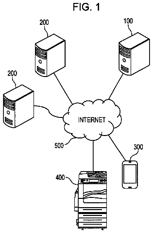
FIG. 1 is a diagram illustrating an example of the configuration of an information distribution system according to a first embodiment;
FIG. 2 is a diagram illustrating an example of the hardware configuration of an information processing device in the first embodiment;
FIG. 3 is a diagram illustrating an example of functional blocks of the information processing device in the first embodiment;
FIG. 4 is a diagram illustrating an example of a printing (digitization) setting screen in the first embodiment;
FIG. 5 is a diagram illustrating an example of drawing objects in the first embodiment;
FIG. 6 is a diagram illustrating an example of pieces of address specification information of a plug-in B in the first embodiment;
FIG. 7 is a diagram illustrating an example of plug-in information in the first embodiment;
FIG. 8 is a diagram illustrating an example of a selection screen of a type of a transmission destination device in the first embodiment;
FIG. 9 is a diagram illustrating an example of a selection screen of the transmission destination device in the first embodiment;
FIG. 10 is a diagram illustrating a first example of a confirmation screen in the first embodiment;
FIG. 11 is a diagram illustrating a second example of the confirmation screen in the first embodiment;
FIG. 12 is a diagram illustrating an example of a transmission destination device management screen in the first embodiment;
FIG. 13 is a diagram illustrating an example of pieces of information that are transmitted from the information processing device in the first embodiment;
FIG. 14 is a diagram illustrating schematic data flow in an information distribution method in the first embodiment;
FIG. 15 is a flowchart illustrating an example of the information distribution method in the first embodiment;
FIG. 16 is a diagram illustrating an example of sequence of the information distribution method in the first embodiment;
FIG. 17 is a diagram illustrating an example of functional blocks of an information processing device according to a second embodiment;
FIG. 18A is a diagram illustrating a first example of setting information in the second embodiment;
FIG. 18B is a diagram illustrating a second example of the setting information in the second embodiment; and
FIG. 19 is a flowchart illustrating an example of a version determination method in the second embodiment.
The accompanying drawings are intended to depict exemplary embodiments of the present invention and should not be interpreted to limit the scope thereof. Identical or similar reference numerals designate identical or similar components throughout the various drawings.
Description of the embodiments
The terminology used herein is for the purpose of describing particular embodiments only and is not intended to be limiting of the present invention.
As used herein, the singular forms “a”, an and the are intended to include the plural forms as well, unless the context clearly indicates otherwise.
In describing preferred embodiments illustrated in the drawings, specific terminology may be employed for the sake of clarity. However, the disclosure of this patent specification is not intended to be limited to the specific terminology so selected, and it is to be understood that each specific element includes all technical equivalents that have the same function, operate in a similar manner, and achieve a similar result.
An embodiment of the present invention will be described in detail below with reference to the drawings.
An object of an embodiment is to provide an information distribution system capable of transmitting data to various devices including a printer by a unified operation with a printing operation without causing a user to be conscious of a usable data format and managing a version of the data.
Hereinafter, embodiments will be described in detail with reference to the accompanying drawings.
First Embodiment
First, the configuration of an information distribution system according to a first embodiment will be described. FIG. 1 is a diagram illustrating an example of the configuration of an information distribution system 400 in the first embodiment. The information distribution system 400 in the first embodiment includes an information processing device 100 , a smart device 200 a , a server device 200 b , a printing device 200 c , and a cloud service system 200 d . The information processing device 100 , the smart device 200 a , the server device 200 b , the printing device 200 c , and the cloud service system 200 d are coupled to one another via a network 300 . In the information distribution system 400 in the first embodiment, the information processing device 100 transmits data (for example, image data) to the respective devices (the smart device 200 a , the server device 200 b , the printing device 200 c , and the cloud service system 200 d ) via the network 300 . Hereinafter, when types of the devices are not distinguished from one another, they are simply referred to as a device 200 .
Specific examples of the respective devices in FIG. 1 will be described. The information processing device 100 is a personal computer or the like. The smart device 200 a is a smartphone, a tablet terminal, or the like. The server device 200 b is a device on which pieces of electronic data (image data and the like) to be referred in a conference system or the like established by a plurality of terminals are uploaded. The printing device 200 c is a printer, a multi function printer (MFP), or the like. The cloud service system 200 d is a system providing service using the uploaded pieces of electronic data on the Internet. The cloud service system 200 d is DropBox (registered trademark) or SkyDrive (registered trademark), for example.
Next, the hardware configuration of the information processing device 100 in the first embodiment will be described. FIG. 2 is a diagram illustrating an example of the hardware configuration of the information processing device 100 in the first embodiment. The information processing device 100 in the first embodiment includes a central processing unit (CPU) 11 , a read only memory (ROM) 12 , a random access memory (RAM) 13 , an external interface (I/F) 14 , a communication device 15 , an input device 16 , a display device 17 , and a storage device 18 . The CPU 11 , the ROM 12 , the RAM 13 , the external I/F 14 , the communication device 15 , the input device 16 , the display device 17 , and the storage device 18 are connected to one another via a bus 21 .
The CPU 11 is a device controlling operations of the information processing device 100 . The ROM 12 is a read-only nonvolatile storage medium. The ROM 12 stores therein a computer program such as firmware. The RAM 13 is a volatile storage medium from and into which information is readable and writable at high speed. The RAM 13 is used as a work region when the CPU 11 processes information. The external I/F 14 is an interface for connecting an external device such as a storage medium 20 to the bus 21 . The communication device 15 communicates with the other devices 200 via the network 300 . The input device 16 is a user interface enabling the user to input information to the information processing device 100 . The input device 16 is a keyboard and a mouse, for example. The display device 17 is a visual user interface enabling the user to check a state of the information processing device 100 . The display device 17 is a liquid crystal display (LCD), for example. The storage device 18 is a nonvolatile storage medium from and into which information is readable and writable.
The storage device 18 stores therein an operating system (OS) 10 , an application 30 , a printer driver 31 , and the like. The OS 10 is a computer program controlling the entire system of the information processing device 100 . The application 30 is a computer program operating with the OS 10 and performs predetermined processing. The application 30 is document creation software or spreadsheet software, for example. The printer driver (digitizing driver) 31 converts printing (digitization) target data into a data format for printing or a data format capable of being used by a transmission destination device. Hereinafter, the printing (digitization) target data is referred to as first data. Data that is formed based on the first data is referred to as second data. To be specific, the second data is data formed by converting the first data into the data format for printing or the data format capable of being used by the transmission destination device. The printer driver (digitizing driver) 31 will be described in detail later with reference to FIG. 3 .
Next, the functional blocks of the information processing device 100 in the first embodiment will be described. FIG. 3 is a diagram illustrating an example of the functional blocks of the information processing device 100 in the first embodiment. The information processing device 100 in the first embodiment includes the application 30 , the printer driver 31 , a distribution controller 41 , and plug-ins (a plug-in A, a plug-in B, and a plug-in C). The printer driver 31 includes a receiver 32 , a display controller 33 , a generator 34 , and a drawing unit 35 . The drawing unit 35 includes an extracting unit 36 and a converter 37 .
Furthermore, the information processing device 100 stores therein plug-in information 51 , history information 52 , pieces of data format information 53 a to 53 c , and pieces of address specification information 54 a to 54 c . Hereinafter, when the pieces of data format information 53 a to 53 c are not distinguished from one another, they are simply referred to as data format information 53 . In the same manner, when the pieces of address specification information 54 a to 54 c are not distinguished from one another, they are simply referred to as address specification information 54 . The distribution controller 41 in the first embodiment is provided as a computer program just as the application 30 and the printer driver 31 . The plug-in A, the plug-in B, and the plug-in C are computer programs capable of being added to or deleted from the information processing device 100 .
The application 30 transmits a printing (digitization) request indicating a request for printing (digitization) processing to the receiver 32 of the printer driver 31 . The receiver 32 receives the printing (digitization) requests from various applications 30 . The printing (digitization) request contains the first data which is a target of the printing (digitization) processing. The first data is data contained in application data that the application 30 opens. The printing (digitization) request is generated when printing is selected from a menu of a UI of the application 30 , for example. When the receiver 32 receives the printing (digitization) request from the application 30 , it inputs the printing (digitization) request to the display controller 33 and the generator 34 . When the display controller 33 receives the printing (digitization) request from the receiver 32 , it causes display of a printing (digitization) setting screen on the display device 17 .
FIG. 4 is a diagram illustrating an example of the printing (digitization) setting screen in the first embodiment. The display controller 33 receives, from a user, input indicating specifications of printing (digitization) settings including selection of color or monochrome, paper orientation, resolution, the number of copies, both-sided printing, aggregate printing, bookbinding, and magnification through the printing (digitization) setting screen. The specifications of the printing (digitization) settings are placed by pressing a print button.
Referring back to FIG. 3 , the display controller 33 inputs, to the generator 34 , printing setting data indicating the printing settings specified by the user through the printing (digitization) setting screen. The generator 34 receives the first data from the receiver 32 and receives the printing setting data from the display controller 33 . The generator 34 generates a job for printing (digitizing) the first data based on the printing setting data. The job contains the first data, the printing setting data, a job name, a user name, and an application name. The job name is a name of the job. The job name is specified by the printing (digitization) request that the receiver 32 has received from the application 30 . The job name contains a name of the application data, for example. The user name is a name of the user of the application 30 . The application name is a name of the application 30 as a transmission source of the printing (digitization) request. The generator 34 inputs the job to the extracting unit 36 and the converter 37 .
When the extracting unit 36 receives a job from the generator 34 , it extracts characteristic information indicating characteristics of the first data contained in the job based on the printing setting data contained in the job. The characteristic information is, for example, the total number of pages of the first data and drawing object information contained in the first data. The drawing object information is information specifying drawing objects. The drawing object information is the number, the types, the positions, characteristics, and the like of the drawing objects, for example. The types of the drawing objects are a character, a figure, and an image, for example.
FIG. 5 is a diagram illustrating an example of the drawing objects in the first embodiment. In the example of FIG. 5 , a printing (digitization) target page contained in the first data includes a character string 101 , a FIG. 102 , a FIG. 103 , and an image 104 as the drawing objects.
The coordinates indicating the position of the character string 101 in the printing (digitization) target page are (100, 100). Characteristics of the character string 101 are contents “ABCDEFGHIJ” of the character string, a color of characters, a font of the characters, and a script type of the characters, for example.
The coordinates indicating the position of the FIG. 102 in the printing (digitization) target page are (800, 1500). The coordinates indicating the position of the FIG. 103 in the printing (digitization) target page are (1000, 1800). Characteristics of the FIG. 102 and the FIG. 103 are lines, passes, painted colors, and overlapping colors, for example.
The coordinates indicating the position of the image 104 in the printing (digitization) target page are (100, 4000). Characteristics of the image 104 are the width of the image, the height of the image, and the number of colors of the image, for example.
Referring back to FIG. 3 , the extracting unit 36 transmits the job and the characteristic information of the first data to a determiner 44 of the distribution controller 41 . The extracting unit 36 is included in the drawing unit 35 of the printer driver 31 because it is preferable that the characteristic information of the first data be extracted before the first data is converted into the second data. The second data is electronic data in such a data format as a PDF format, an XPS format, a TIFF format, a JPEG format, or the like. It is therefore difficult to extract the characteristic information from the second data. It should be noted that the characteristic information indicating the characteristics of the first data and characteristic information indicating the characteristics of the second data are the same because the second data is data formed by converting the data format of the first data.
Then, operations of the converter 37 will be described. When the converter 37 receives the job from the generator 34 , it inquires at an acquiring unit 42 of the distribution controller 41 about the data format information 53 . The data format information 53 indicates one or more data formats capable of being used by the transmission destination devices. Any data format may be stored as the data format information 53 . Hereinafter, in the description of the first embodiment, the data format that is stored as the data format information 53 is assumed to be the data format of image data, such as the PDF format, the XPS format, the TIFF format, and the JPEG format.
The plug-in controls storage of the data format information 53 . The plug-in is described herein. The plug-in in the first embodiment is installed in the information processing device 100 for each type of the transmission destination devices for the second data. The plug-in is installed as described above so as to be added to or deleted from the information processing device 100 by executing transmission processing of the second data with the plug-in for each type of the transmission destination devices because transfer protocols and usable data formats are different among the types of the transmission destination devices. With the above, even when a device of a new type appears, the second data formed based on the first data can be transmitted to the device by a unified operation with the printing operation only by adding a plug-in corresponding to the device to the information processing device 100 . As the data format information 53 , resolution of the second data, minimum sizes and maximum sizes of the length and the width of the second data, and the like may be stored in addition to the data format of the second data.
Furthermore, the plug-in controls storage of one or more pieces of address specification information 54 in addition to the data format information 53 . FIG. 6 is a diagram illustrating an example of the pieces of address specification information 54 b of the plug-in B in the first embodiment. In the example of FIG. 6 , the address specification information 54 b contains an ID, a name, and an address. The ID is an identifier uniquely specifying the transmission destination device. The name is a name of the transmission destination device. The address is information specifying a location of the transmission destination device. The address is an IP address, for example. In the example of FIG. 6 , the name of the transmission destination device, ID of which is specified by “000A1”, is “A's tablet” and the address thereof is “123.456.789.XXX”, for example.
Referring back to FIG. 3 , the plug-in A, the plug-in B, and the plug-in C are installed in the information processing device 100 in the first embodiment. The number of plug-ins that are installed in the information processing device 100 is not limited to three and any number thereof may be installed. In the information processing device 100 in the first embodiment, the plug-in A is assumed to be a plug-in corresponding to a conference system, the plug-in B is assumed to be a plug-in corresponding to a smart device, and the plug-in C is assumed to be a plug-in corresponding to a printing device. Furthermore, it is assumed that the data format information 53 a of the plug-in A indicates the PDF format, the data format information 53 b of the plug-in B indicates the PDF format and the JPEG format, and the data format information 53 c of the plug-in C indicates an EMF format.
When the acquiring unit 42 receives inquiry about the data format information 53 from the converter 37 , it specifies a valid plug-in with reference to the plug-in information 51 . FIG. 7 is a diagram illustrating an example of the plug-in information 51 in the first embodiment. In the example of FIG. 7 , the plug-in information 51 contains a name and a state. The name is a name of the plug-in. The state indicates whether the plug-in is valid or invalid. In the example of FIG. 7 , for example, the name of the plug-in A is “conference system” and the state of the plug-in A is “valid”. When the plug-in information 51 is under a condition of FIG. 7 , the acquiring unit 42 specifies the valid plug-ins to be the plug-in A and the plug-in B.
Subsequently, the acquiring unit 42 acquires the data format information 53 from the valid plug-in. In the example of FIG. 7 , the acquiring unit 42 acquires the data format information 53 a from the plug-in A and acquires the data format information 53 b from the plug-in B because the valid plug-ins are the plug-in A and the plug-in B. As described above, in the information processing device 100 in the first embodiment, the data format information 53 a of the plug-in A is the PDF format. The acquiring unit 42 therefore acquires information indicating the PDF format as the data format information 53 a from the plug-in A. In the same manner, the data format information 53 b of the plug-in B is the PDF format and the JPEG format. The acquiring unit 42 therefore acquires information indicating the PDF format and information indicating the JPEG format as the data format information 53 b from the plug-in B.
Then, the acquiring unit 42 transmits the data format information 53 acquired from the valid plug-in to the converter 37 of the printer driver 31 .
Subsequently, when the converter 37 receives the job from the generator 34 and receives the data format information 53 from the acquiring unit 42 , it converts the first data into one or more pieces of second data in the data formats defined by the pieces of data format information 53 based on the printing setting data contained in the job. In the example of FIG. 7 , the converter 37 receives the above-mentioned data format information 53 a and the above-mentioned data format information 53 b from the plug-in A and the plug-in B and converts the first data into the pieces of second data in the PDF format and the JPEG format. Thereafter, the converter 37 transmits the second data to a distributing unit 45 .
Then, a display controller 43 requests the acquiring unit 42 to acquire the address specification information 54 . The acquiring unit 42 acquires the address specification information 54 from the valid plug-in. In the example of FIG. 7 , the acquiring unit 42 acquires the address specification information 54 a from the plug-in A and acquires the address specification information 54 b from the plug-in B because the valid plug-ins are the plug-in A and the plug-in B. The acquiring unit 42 inputs the address specification information 54 acquired from the valid plug-in to the display controller 43 .
Subsequently, when the display controller 43 receives the address specification information 54 from the acquiring unit 42 , it causes display of a selection screen for selecting the transmission destination device on the display device 17 . FIG. 8 is a diagram illustrating an example of the selection screen of a type of the transmission destination device in the first embodiment. FIG. 9 is a diagram illustrating an example of the selection screen of the transmission destination device in the first embodiment. FIG. 8 and FIG. 9 illustrate an example of the case in which first, the type of the transmission destination device is selected on the screen in FIG. 8 , and then, the addresses of the transmission destination devices of the selected type are displayed on the screen in FIG. 9 . The screen in FIG. 8 is displayed after the conversion processing of the first data that is executed after the print button on the screen in FIG. 4 is pressed and the acquisition processing of the address specification information 54 that is displayed as the candidate. The example of FIG. 9 illustrates the case when the smart device has been selected as the type of the transmission destination device on the selection screen in FIG. 8 . The display controller 43 may cause display of all the transmission destination devices as the destination candidates at a time without hierarchizing the display of the destinations as in the examples of FIG. 8 and FIG. 9 .
Referring back to FIG. 3 , the display controller 43 inputs the address specification information 54 selected by the user through the screens in FIG. 8 and FIG. 9 to the determiner 44 .
The determiner 44 receives the above-mentioned job and characteristic information from the extracting unit 36 and receives the selected address specification information 54 from the display controller 43 . The determiner 44 determines, based on the history information 52 , whether the first data characterized by the characteristic information relates to first data which is a conversion source of one or more pieces of second data that have been already transmitted to the devices specified by the pieces of address specification information 54 . Furthermore, the determiner 44 determines version information of the first data based on the history information 52 .
First, the history information 52 is described. The distributing unit 45 creates the history information 52 for each job generated by the generator 34 . The distributing unit 45 stores the history information 52 related to the second data after it distributes the second data.
The history information 52 is stored while job specification information, characteristic information, device specification information, and version information are associated with each other.
The job specification information is information specifying a job. The job specification information contains the above-mentioned job name, the above-mentioned user name, the above-mentioned application name, and distribution date and time. The distribution date and time are date and time at which the second data based on the first data was distributed.
The characteristic information is the above-mentioned characteristic information extracted from the first data by the extracting unit 36 .
The device specification information is information specifying the transmission destination device of the one or more pieces of second data obtained by converting the data format of the first data.
The version information is version information of the first data. The determiner 44 determines the version information.
The data of the history information 52 is uniquely identified by the job specification information.
Operations of the determiner 44 will be described in detail. First, the determiner 44 acquires a difference between the characteristic information that the data of the history information 52 has and the characteristic information extracted by the extracting unit 36 . The difference in the characteristic information is a difference in the total number of pages of the first data and a difference in the number of drawing objects contained in the first data, for example.
Then, the determiner 44 determines whether the first data is updated first data which is as a conversion source of second data that has been already transmitted to any device using a determination criterion. Any determination criterion for determining whether to change the version information may be used. An example of the determination criterion will be described as follows.
The determiner 44 may use a first determination criterion according to which the version information of the first data is changed when the data amount (data amount indicating the difference in the characteristic information) indicating the difference between the pieces of first data is larger than 0 and is equal to or smaller than a threshold, for example. When the data amount indicating the difference between the pieces of first data is larger than the threshold, the determiner 44 determines that the first data is not the updated data and these pieces of first data are different from each other.
The determiner 44 may use a second determination criterion according to which the version information of the first data is changed when the above-mentioned application name contained in the job and the application name contained in the job specification information in the history information 52 match each other and the job name contained in the job and the job name contained in the history information 52 match each other, for example.
The determiner 44 may use a third determination criterion according to which the version information of the first data is changed when the total number of pages of the first data is increased and the number of drawing objects in the page is increased.
The determiner 44 may determine whether the version information be changed using a plurality of determination criteria. For example, the determiner 44 may change the version information when the above-mentioned second determination criterion is satisfied and the above-mentioned third determination criterion is satisfied.
Moreover, the display controller 43 may cause display of a confirmation screen for enabling the user to confirm change of the version information before the determiner 44 determines to change the version information.
FIG. 10 is a diagram illustrating a first example of the confirmation screen in the first embodiment. The example of FIG. 10 illustrates the case in which one confirmation screen is displayed for each transmission destination device. In the example of FIG. 10 , the job name (specification.doc), the application name (application A), and the date and time of previous printing (2015/02/03 19:00) are displayed. The example of FIG. 10 uses specification.doc in which a name (file name) of the application data containing the first data is used as the job name.
When a new registration button in FIG. 10 is pressed, the determiner 44 determines the version of the first data to a version when the second data based on the first data is newly registered. The version when the data is newly registered is V1.0, for example.
When an overwriting registration button in FIG. 10 is pressed, the determiner 44 determines to update the version of the first data. When the current version of the first data is V1.0, the determiner 44 updates the version to V1.1, for example.
FIG. 11 is a diagram illustrating a second example of the confirmation screen in the first embodiment. The example of FIG. 11 illustrates the case in which confirmation for a plurality of transmission destination devices is made on one confirmation screen. In the example of FIG. 11 , an ID, a name, a checkbox, and transmission history are displayed for each of the transmission destination devices. The ID is identification information identifying the device. The name is a name of the transmission destination device. The checkbox indicates whether overwriting registration is performed. When the checkbox is checked, it indicates to perform the overwriting registration. When the checkbox is not checked, it indicates not to perform the overwriting registration. Operation input by the user changes the state of the checkbox.
The transmission history indicates whether the second data formed by converting the data format of the first format has been already transmitted. For example, the transmission history indicates that the second data based on the first data of V1.0 has been transmitted to the device A; it also indicates, as an example, that the second data based on the first data has never been transmitted to the device B and the device C.
When a transmission button in FIG. 11 is pressed, the distributing unit 45 transmits the second data based on the first data to the respective transmission destination devices using the plug-ins corresponding to the transmission destination devices.
When a cancel button in FIG. 11 is pressed, transmission of the second data based on the first data is cancelled.
Referring back to FIG. 3 , the distributing unit 45 transmits the second data based on the first data and information indicating the version of the first data to the transmission destination device selected through the selection screens in FIG. 8 and FIG. 9 using the plug-in. In this case, the distributing unit 45 may transmit other pieces of information that are used in the transmission destination device at the same time.
FIG. 13 is a diagram illustrating an example of the pieces of information that are transmitted from the information processing device 100 in the first embodiment. In the example of FIG. 13 , when the information processing device 100 transmits the second data to the smart device 200 a using the plug-in B, it transmits a job name, an application name, transmission date and time, a version, and registration information. In the example of FIG. 13 , the name of the application data is used as the job name. The application name indicates a name of the application that opens the application data. The transmission date and time are the date and time at which the second data was transmitted.
The registration information is information indicating the new registration or the overwriting registration. The new registration is a registration method when the first data which is the conversion source of the one or more pieces of second data is not related to first data which is a conversion source of one or more pieces of second data that have been already transmitted. The overwriting registration is a registration method when the first data which is the conversion source of the one or more pieces of second data relates to the first data which is the conversion source of the one or more pieces of second data that have been already transmitted. The registration information is identification information such as an ID, for example. For example, in the case of the new registration, the information processing device 100 (distributing unit 45 ) associates a new ID with the first data and transmits the ID to the smart device 200 a . In the case of the overwriting registration, the information processing device 100 (distributing unit 45 ) transmits the existing ID associated with the second data to the smart device 200 a.
When the registration information received from the information processing device 100 indicates the new registration, the smart device 200 a newly registers (stores) the second data received from the information processing device 100 in a manner associated with the ID notified as the registration information. In this case, the smart device 200 a may display, on a screen, reception of new data that has not been registered in the smart device 200 a from the information processing device 100 .
When the registration information received from the information processing device 100 indicates the overwriting registration, the smart device 200 a overwrites the data in the smart device 200 a that is associated with the ID notified as the registration information with the second data received from the information processing device 100 . In this case, the smart device 200 a may display, on the screen, reception of data, version of which has been upgraded, from the information processing device 100 .
Referring back to FIG. 3 , the distributing unit 45 stores the above-mentioned history information 52 for each job. To be specific, the distributing unit 45 stores the job specification information (the job name, the user name, the application name, and the distribution date and time), the characteristic information, the device specification information, and the version information associated with each other. The job name, the user name, and the application name contained in the job generated by the generator 34 are stored as the job name, the user name, and the application name. As the distribution date and time, the date and time at which the second data based on the first data has been distributed are stored. As the characteristic information, the characteristic information extracted from the first data by the extracting unit 36 is stored. As the device specification information, information specifying the device to which the second data based on the first data has been transmitted is stored. As the version information, the version determined by the determiner 44 is stored.
The description continues in the full USPTO document.
 Lapsed, fee not paid6 drawings