Background of the invention
Field of the Invention
The present invention relates to an image forming apparatus and a method for controlling the image forming apparatus.
Description of the Related Art
Hard disk drives (HDDs) are nonvolatile storage devices. HDDs have advantages including a low price per bit, high capacity, and an unlimited number of rewrite cycles, but have disadvantages including intermediate-speed processing performance and vulnerability to vibrations because of their mechanical structures. In recent years, solid-state drives (SSDs) using flash memories have been rapidly spreading. SSDs are storage devices including semiconductor elements and thus are resistant to vibrations. SSDs also have an advantage of processing speed twice or more as high as that of HDDs. SSDs have however fewer rewrite cycles per block unit due to miniaturization. Multi-level cell (MLC) SSDs have a number of rewrite cycles as extremely small as approximately 1000 to 3000 cycles. Although the high-speed performance of SSDs is advantageous, the SSDs' short service life in terms of rewrite cycles is a fatal disadvantage to cache systems, database apparatuses, and printing apparatuses in which the rewriting frequency is high.
Methods for extending the service life of a storage device, such as an SSD, using flash memory have been known. Japanese Unexamined Patent Application Publication (Translation of PCT Application) No. 2013-513186 discusses a data cache system including a hybrid configuration of an SSD and an HDD. According to Japanese Unexamined Patent Application Publication (Translation of PCT Application) No. 2013-513186, a data write cache is temporarily stored in the HDD, and the cached data is transferred to the SSD according to a transfer policy in consideration of the service life of the SSD.
Japanese Patent Application Laid-Open No. 2012-14632 discusses a service life extension method in which a data table of high update frequency is generated on a long service life storage device (HDD) and a table data of low update frequency is generated on a flash memory based on the update frequency of data, based on the update frequency of write data, in a database apparatus.
However, the methods discussed in Japanese Unexamined Patent Application Publication (Translation of PCT Application) No. 2013-513186 and Japanese Patent Application Laid-Open No. 2012-14632 are difficult to apply to high-end printing apparatuses which need to realize both high resolution and high-speed printing. The method discussed in Japanese Unexamined Patent Application Publication (Translation of PCT Application) No. 2013-513186 is not able to satisfy an output page per minute (PPM) specification of the printing apparatuses because of the processing performance of the HDD. The method discussed in Japanese Patent Application Laid-Open No. 2012-14632 is difficult to apply to a printing apparatus, from the viewpoint of statistic values such as update frequency.
Summary of the invention
According to an aspect of the present invention, an image forming apparatus for processing print data includes a control unit configured to control a plurality of nonvolatile storage devices having different transfer rates, and a determination unit configured to determine a nonvolatile storage device to store print data from among the plurality of nonvolatile storage devices based on information related to a size of the print data, information related to the transfer rates of the plurality of nonvolatile storage devices, and a threshold value depending on the number of sheets to be printed and output per unit time. The control unit and the determination unit are implemented by one or more processor.
Further features of the present invention will become apparent from the following description of exemplary embodiments with reference to the attached drawings.
Brief description of the drawings
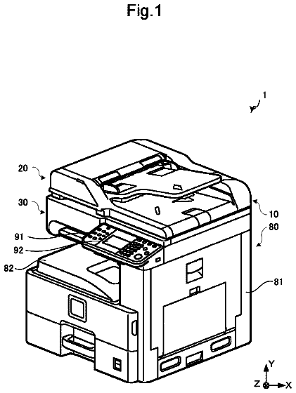
FIG. 1 is a diagram illustrating a configuration example of a printing system.
FIG. 2 is a diagram illustrating a configuration example of a Serial Advanced Technology Attachment (SATA) control unit.
FIG. 3 is a diagram illustrating a configuration example of a compression processing unit.
FIG. 4 is a diagram illustrating a configuration example of a storage management table.
FIG. 5 is a diagram illustrating a configuration example of an m file management table on a main memory.
FIG. 6 is a diagram illustrating a configuration example of an s file management table on storage devices.
FIGS. 7A and 7B are diagrams each illustrating a configuration example of a descriptor table.
FIG. 8 is a diagram illustrating an example of a mapping configuration on the main memory.
FIG. 9 is a diagram illustrating an example of a mapping configuration on a static random access memory (SRAM) included in the SATA control unit.
FIG. 10 is a flowchart illustrating generation processing of a logical block addressing (LBA) management table.
FIG. 11 is a flowchart illustrating processing for generating the m file management table on the main memory.
FIG. 12 is a flowchart illustrating processing for generating the s file management table on the storage devices.
FIG. 13 is a flowchart illustrating data transfer processing with the descriptor table.
FIG. 14 is a flowchart illustrating a service life determination processing.
FIG. 15 is a diagram illustrating a configuration example of connection of an encryption apparatus.
FIG. 16 is a diagram illustrating a configuration example of the encryption apparatus.
FIG. 17 is a diagram illustrating examples of extended commands for control and status acquisition of the encryption apparatus.
FIG. 18 is a flowchart illustrating command processing of the encryption apparatus.
Description of the embodiments
FIG. 1 is a diagram illustrating a configuration example of a printing system according to a first exemplary embodiment of the present invention. The printing system includes a printing apparatus, a local area network 106 , and a host computer 107 . The printing apparatus includes a main controller 122 , an external image processing apparatus 108 , a scanner apparatus 111 , a hard disk drive (HDD) 114 , a solid-state drive (SSD) 115 , a read-only memory (ROM) 116 , a flash memory 103 , a dynamic random access memory (DRAM) 104 , a panel apparatus 118 , and a print unit 120 . The HDD 114 is a nonvolatile storage device. The SSD 115 is a nonvolatile storage device with flash memory. The SSD 115 has a write speed and a read speed higher than those of the HDD 114 . In other words, the HDD 114 and the SSD 115 have different write speeds and read speeds. The main controller 122 includes a main central processing unit (CPU) 101 , a memory control unit 102 , a local area network interface (LAN-IF) unit 105 , a compression processing unit 109 , a reader interface (IF) unit 110 , an image processing unit 112 , a Serial Advanced Technology Attachment (SATA) control unit 113 , a panel IF unit 117 , and a video output IF unit 119 . The main controller 122 further includes a main bus 121 .
The main CPU 101 is a control unit, and performs system control and various types of arithmetic processing. The memory control unit 102 performs input/output control and direct memory access (DMA) control on various memory devices including the flash memory 103 and the DRAM 104 . The flash memory 103 is rewritable nonvolatile memory, and stores a control program and control parameters of the entire system. The DRAM 104 is a volatile memory dedicated to rewriting, typified by a double data rate (DDR) memory. The DRAM 104 is used as a work area of a program, a storage area of print data, and a storage area of various types of table information. The relationship here between the memory control unit 102 and the various memory devices is a simplified representation, and the memory devices are independently controlled. The LAN-IF unit 105 is an interface unit for the local area network 106 . The LAN-IF unit 105 supports, for example, the Transmission Control Protocol/Internet Protocol (TCP/IP). The printing apparatus is connected to network-compatible apparatuses, such as the external host computer 107 , via the local area network 106 and can perform printing.
The external image processing apparatus 108 performs various types of image processing on print data received via the local area network 106 , and transmits image data to the compression processing unit 109 . The external image processing apparatus 108 is connected to the LAN-IF unit 105 on a one-to-one basis, and transmits and receives print information and a status. The compression processing unit 109 compresses the image data from the external image processing apparatus 108 and stores the compressed data into a predetermined location in the DRAM 104 via the memory control unit 102 . Examples of the compression method include lossless compression and Joint Photographic Experts Group (JPEG) compression. The reader IF unit 110 is an interface unit for performing communication control on the scanner apparatus 111 . The scanner apparatus 111 generates image data by scanning. The main controller 122 causes the print unit 120 to print the image data scanned by the scanner apparatus 111 to implement a copy function. The image processing unit 112 performs various types of image processing on the image data input via the LAN-IF unit 105 or the reader IF unit 110 .
The SATA control unit 113 performs data input/output control with devices having an interface compliant with the SATA standard. The SATA control unit 113 is connected with the HDD 114 and the SSD 115 , which are nonvolatile storage devices. The ROM 116 stores various parameters and a control program of a first sub CPU 201 ( FIG. 2 ) included in the SATA control unit 113 . When the printing apparatus is activated, the first sub CPU 201 performs boot processing for activation according to the program of the ROM 116 independently of the main CPU 101 . The internal configuration of the SATA control unit 113 will be described below with reference to FIG. 2 . The panel IF unit 117 performs communication control on the panel apparatus 118 . The panel apparatus 118 serves as a user interface (UI). A user can set various settings and check a state of the printing apparatus by operating a liquid crystal screen display and buttons on the panel of the panel apparatus 118 . The video output IF unit 119 performs command/status communication control on, and transfers print data to, the print unit 120 . The print unit 120 includes a print unit main body, a sheet feed system, and a sheet discharge system. The print unit 120 prints the print data on paper mainly according to command information from the video output IF unit 119 . The main bus 121 includes a bus controller, a control bus, and a data bus, and a local bus between certain blocks. The main bus 121 includes a Peripheral Component Interconnect Express (PCIe) bus and an internal bus of an application specific integrated circuit (ASIC).
The compressed data compressed by the compression processing unit 109 is written to the HDD 114 or the SSD 115 . The compression processing unit 109 also decompresses the compression data written to the HDD 114 or the SSD 115 . The print unit 120 prints the image data decompressed by the compression processing unit 109 .
FIG. 2 is a diagram illustrating an internal configuration example of the SATA control unit 113 . The SATA control unit 113 includes the first sub CPU 201 , a memory control unit 202 , a static random access memory (SRAM) 203 , a first SATA port control unit 204 , a second SATA port control unit 206 , a direct memory access controller (DMAC) 208 , and a first sub bus 209 . The first sub CPU 201 is a SATA controller. The first sub CPU 201 is a control unit for performing overall control, including SATA command issue processing, transfer processing for transmission and reception data, SATA status reception processing, and various types of calculation processing. The memory control unit 202 performs input/output control on the ROM 116 and the SRAM 203 , and interrupt processing on the first sub CPU 201 . The SRAM 203 includes a work area of the first sub CPU 201 , various control tables, a parameter storage area, and a data buffer. The memory control unit 202 and the SRAM 203 each independently control a one-port RAM, a two-port RAM, and/or a first-in first-out (FIFO) memory. The memory control unit 202 and the SRAM 203 may include a plurality of such memories.
The SATA port control units 204 and 206 include the SATA link layer and physical layer. The first sub CPU 201 sets various SATA registers of the SATA port control units 204 and 206 . According to the settings of the various SATA registers, the SATA port control units 204 and 206 issue physical (electrical signal) commands to and receive statuses of the SATA standard from the HDD 114 and the SSD 115 connected to SATA-IFs 205 and 207 . The HDD 114 is connected to the first SATA port control unit 204 . The SSD 115 is connected to the second SATA port control unit 206 . The DMAC 208 performs data transfer between predetermined memories if the first sub CPU 201 sets a start address of the transfer destination and a size into a predetermined register and instructs the DMAC 208 to start. The first sub bus 209 includes a bus controller, a control bus, a data bus, and a local bus between predetermined blocks. The first sub bus 209 is connected to the main bus 121 . The main CPU 101 can read from and write to the SRAM 203 via the first sub bus 209 . The DMAC 208 performs transfer processing for reading and writing data between the SRAM 203 and the DRAM 104 , which is a main memory, via the main bus 121 and the first sub bus 209 .
FIG. 3 is a diagram illustrating an internal configuration example of the compression processing unit 109 . The compression processing unit 109 includes a video input IF unit 301 , a memory control unit 302 , an SRAM 303 , a compression/decompression processing unit 304 , a DMAC 305 , and a second sub bus 306 . The video input IF unit 301 performs input control on the image data from the external image processing apparatus 108 . The memory control unit 302 performs input/output control on the SRAM 303 , and inputs and outputs control signals from/to other functional modules. The SRAM 303 is used as a temporary storage area of the image data. The memory control unit 302 and the SRAM 303 independently control a one-port RAM, a two-port RAM, and/or an FIFO memory. The memory control unit 302 and SRAM 303 may include a plurality of such memories. The compression/decompression processing unit 304 performs compression and decompression processing of the image data. As described above, examples of the compression method include lossless compression and JPEG compression. The compression/decompression processing unit 304 temporarily stores the image data input from the external image processing apparatus 108 into a line buffer in the compression/decompression processing unit 304 . The compression/decompression processing unit 304 sequentially compresses the image data stored in the line buffer, and stores the compressed data into a predetermined location of the SRAM 303 via the memory control unit 302 . For decompression processing, the compression/decompression processing unit 304 temporarily stores the compressed data stored in the predetermined area in the SRAM 303 into the line buffer, performs the decompression processing thereon, and stores the decompressed image data into a predetermined area of the SRAM 303 again.
The DMAC 305 performs DMA control between memories. The DMAC 305 performs data transfer between predetermined memories with a transfer source address, a transfer destination address, and size information being set and an instruction to start being given. The second sub bus 306 includes a bus controller, a control bus, a data bus, and a local bus between certain blocks. The second sub bus 306 is connected to the main bus 121 . The main CPU 101 can access the compression processing unit 109 via the main bus 121 . For example, the main CPU 101 can set a register of and read the DMAC 305 and the compression/decompression processing unit 304 . The DMAC 305 performs transfer processing for reading and writing data between the SRAM 303 and the DRAM 104 , which is the main memory, via the main bus 121 and the second sub bus 306 .
FIG. 4 is a diagram illustrating the storage management table 414 stored in the DRAM 104 , which is the main memory. The storage management table 414 manages various types of information and determination information about the storage devices including the HDD 114 and the SSD 115 . The storage management table 414 includes a logical block addressing (LBA) management table 413 , a performance (PM) threshold value 408 , a service life threshold value 409 , and a current service life value 415 . The LBA management table 413 includes a device number 401 , a total number of sectors 402 , a maximum physical LBA (maximum physical address) 403 , a minimum logical LBA (minimum logical address) 404 , and a maximum logical LBA (maximum logical address) 405 . The device number 401 indicates a serial number of each storage device. In row 406 , the device number 401 indicates the serial number of the HDD 114 . In row 407 , the device number 401 indicates the serial number of the SSD 115 . For example, the total number of sectors 402 of a connected storage device is the number of sectors into which the number of blocks of the connected storage device is converted. The total number of sectors 402 of the HDD 114 is SNA. The total number of sectors 402 of the SSD 115 is SNB. The maximum physical LBA 403 of the HDD 114 is LBAr 1 . The maximum physical LBA 403 of the SSD 115 is LBAr 2 . The minimum logical LBA 404 of the HDD 114 is LBAm 1 (=0 h). The minimum logical LBA 404 of the SSD 115 is LBAn 1 . The maximum logical LBA 405 of the HDD 114 is LBAm 2 . The maximum logical LBA of the SSD 115 is LBAn 2 . The range of logical LBAs (logical addresses) of the HDD 114 is LBAm 1 (=0 h) to LBAm 2 . The range of logical LBAs of the SSD 115 is LBAn 1 to LBAn 2 . The combined logical LBAs of the HDD 114 and the SSD 115 provide serial numbers of 0 h to LBAn 2 . FIG. 4 illustrates a case in which two storage devices, the HDD 114 and the SSD 115 , are managed in rows 406 and 407 . However, the number of storage devices is not limited to two. Three or more storage devices may be connected.
The remaining portion of the storage management table 414 lists parameters used for various determination conditions. The PM threshold value 408 indicates a comparison data size for selecting either the HDD 114 or the SSD 115 according to the size of compressed data to be written to the HDD 114 or the SSD 115 in predetermined units (for example, in units of pages). Assume that an average of the maximum values of write speed obtained through measurement of a plurality of HDDs 114 of the same model number is x MB/s. The processing time for one page is determined by an output page per minute (PPM) performance specification of the printing apparatus. The transfer band required of the HDD 114 can be estimated in advance from budgets of various processing times (such as image processing time, memory-to-memory transfer time, and memory-to-HDD transfer time) for one page. In other words, the data transfer capability (amount of transfer) per second can be estimated in advance. For example, to satisfy performance of 1200 dpi, A4 size, 1/12 compression, and 103 ppm, the HDD 114 needs a write speed of 192 MB/s for a data size of 56 MB for one page. In such a case, the required values are satisfied if the HDD 114 has a write speed of x=200 MB/s. The required values are not satisfied if the HDD 114 has only a write speed of x=180 MB/s. A maximum data size P of one page for the HDD 114 to satisfy a write speed of x MB/s is set as the PM threshold value 408 . The main CPU 101 can determine whether the HDD 114 satisfies the required values by comparing an actual transfer data size (write data size) per page Q with the PM threshold value 408 . The HDD 114 has a write speed lower than that of the SSD 115 . In a case where the actual transfer data size per page Q is smaller than or equal to the PM threshold value 408 , the HDD 114 is selected as the storage device to be used. On the other hand, in a case where the actual transfer data size per page Q is greater than the PM threshold value 408 , the SSD 115 is selected as the storage device to be used. The PM threshold value 408 represents a boundary between the write speeds of a plurality of storage devices (HDD 114 and SSD 115 ). More specifically, the PM threshold value 408 is the maximum data size per page corresponding to the write speed of the HDD 114 . The DRAM 104 is a threshold value storage unit for storing the PM threshold value 408 .
The service life threshold value 409 is used to divide an allowable total write amount of the SSD 115 (e.g., expressed in units of terabytes (TB)) into several sections to determine a service life level. In the present exemplary embodiment, the total write amount is divided into three sections. Service life levels 1 ( 410 ) and 2 ( 411 ) are examples of the two threshold values in descending order of service life. For example, the service life level 1 ( 410 ) is a first threshold value, which represents a yellow zone of caution stage at which the user is informed of replacement of the SSD 115 . The service life level 2 ( 411 ) is a second threshold value, which represents a red zone of warning stage at which the operation of the SSD 115 is completely shifted to that of the HDD 114 . At the service life level 2 ( 411 ), the user is prompted to immediately replace the SSD 115 . The SSD replacement flag 412 is a flag for indicating that the service life threshold value 409 has reached the service life level 2 ( 411 ). A value 0 of the SSD replacement flag 412 indicates that replacement is not needed. A value 1 of the SSD replacement flag 412 indicates that replacement is needed. If the printing apparatus performs service life determination processing upon activation and the SSD replacement flag 412 is one, the service life determination processing is skipped. A warning for SSD replacement is displayed on the UI of the panel apparatus 118 each time the printing apparatus is activated afterward.
The current service life value 415 indicates a cumulative write amount (total write amount) of the SSD 115 up to the previous power-off. The current service life value 415 and the service life threshold value 409 are compared to display a caution or warning according to the service life level on the panel apparatus 118 . For example, the current total write amount can be obtained from Self-Monitoring, Analysis and Reporting Technology (S.M.A.R.T.) information about the SSD 115 . The S.M.A.R.T. information is defined as a SATA standard. The current total write amount may be obtained by adding sizes of data written by each write processing.
FIG. 5 is a diagram illustrating an m file management table 510 stored in the DRAM 104 , which is the main memory. The m file management table 510 includes file information 501 . The file information 501 indicates attribute information 502 about a file. The attribute information 502 includes basic information, such as a file number, a file name, a time stamp, a file size, a sheet size, and the number of pages. The m file management table 510 further includes a page number 503 indicating the number of each page, a compressed page size 504 of the compressed page, a start address 505 at which the page is recorded on the memory, and a data size 506 of a recording area starting at the start address 505 . If a target page is recorded in a continuous space on the memory, the compressed page size 504 and the data size 506 have the same values. If the target page is recorded in discrete spaces, the data size 506 represents the size of the first continuous space, and then the entire target page can be accessed by using a linear list structure. The m file management table 510 lists contents of such items 503 to 506 for each of the first to last nth pages 507 to 509 . FIG. 5 only illustrates entry information about a file in the m file management table 510 . The m file management table 510 includes entry contents for as many as the number of files needed.
FIG. 6 is a diagram illustrating an s file management table 610 stored in the storage devices (HDD 114 and SSD 115 ). The s file management table 610 includes file information 601 . The file information 601 represents attribute information 602 about a file. The attribute information 602 is basically similar to the attribute information 502 in FIG. 5 . The s file management table 610 includes a page number 603 indicating the number of each page, a page size 604 indicating the size of the page, a start logical LBA (start logical address) 605 indicating a start address, and a data size 606 in units of pages. In the present exemplary embodiment, page data on the storage devices is stored in a continuous area. The s file management table 610 lists the contents of the items 603 to 606 for each of the first to last nth pages 607 to 609 . FIG. 6 illustrates entry information about a single file in the s file management table 610 . The s file management table 610 includes entry contents for as many as the number of files needed.
FIGS. 7A and 7B are diagrams each illustrating a configuration example of a descriptor table 719 for writing data on the DRAM (main memory) 104 to the storage devices (HDD 114 and SSD 115 ) in units of pages. The descriptor table 719 includes a command table 717 and a data table 718 .
The command table 717 includes a command entry number 701 , a logical LBA 702 , a sector count 703 , a SATA command number 704 , and an end-of-file (EOF) flag 705 . The command entry number 701 indicates an issue number of a command. The logical LBA 702 indicates a start address. The sector count 703 indicates the number of sectors. The EOF flag 705 represents the state of a final entry. The SATA command number 704 indicates a command number according to the SATA standard (0x35 is a command number for Write DMA Ext). Here, the EOF flag 705 of zero represents continuation, and one an end. The transfer processing of the target page is completed after a command is issued when the EOF flag 705 of 1 is detected. The command table 717 records the contents of the items 701 to 705 for each of the first to last nth entries 706 to 708 of a page.
The data table 718 includes a data entry number 709 , a source address 710 , a destination 711 , a byte count 712 , and an EOF flag 713 . The data entry number 709 indicates a transfer processing number of data. The byte count 712 indicates the amount of transfer data in units of bytes. The EOF flag 713 represents the state of a final entry. The source address 710 indicates the start address of the transfer source of the data, stored in the DRAM (main memory) 104 , which is set by the DMAC 208 (or which is set to the DMAC 208 ) during issuance of a write command. As with the write command, the destination 711 indicates the start address of the destination of transfer at which received data is stored in the DRAM (main memory) 104 in the case of a read command. The EOF flag 713 is similar to the EOF flag 705 . In the present exemplary embodiment, transfer data from the memory corresponding to one command is assumed to be located in a continuous area. The EOF flags 705 and 713 therefore indicate an end at the same entry numbers.
FIG. 8 is a diagram illustrating a part of a memory map of the DRAM (main memory) 104 . A work area 801 , a page data area 802 , an m file management table area 803 , a storage management table area 804 , and an s file management table area 805 are created on the DRAM 104 in a printable normal mode. The page data area 802 stores page data. The m file management table area 803 stores the m file management table 510 . The storage management table area 804 stores the storage management table 414 . The s file management table area 805 stores the s file management table 610 . A print information storage area 806 is an area storing print information (attribute information needed for printing, such as a page size, the number of pages, and color information) that the main CPU 101 obtains through communication with the external image processing apparatus 108 via the LAN-IF unit 105 as described above.
FIG. 9 is a diagram illustrating a part of a memory map on the SRAM 203 included in the SATA control unit 113 . A work area 901 , a command area 902 , a descriptor table area 903 , and an LBA management table area 904 are created on the SRAM 203 in the printable normal mode. Various commands of the SATA standard are set in the command area 902 . The descriptor table area 903 stores the descriptor table 719 . The LBA management table area 904 stores the LBA management table 413 which is a part of the storage management table 414 . Here, the command area 902 is not intended for a continuous command transfer using the descriptor table 719 . Commands for a programmed input/output (PIO) transfer mode or non-data transfer mode other than the DMA transfer mode defined by the SATA standard are set in the command area 902 . The command area 902 is thus used to perform a sporadic command transfer.
Here, the table areas 803 to 805 described in FIG. 8 are saved from the DRAM (main memory) 104 to the flash memory 103 in a case where the normal mode capable of immediate printing is shifted to a power saving mode or a power-off state. When the normal mode is restored, the table areas 803 to 805 are written back to the predetermined table areas 803 to 805 of the DRAM (main memory) 104 again. Similarly, the table areas 903 and 904 described in FIG. 9 are saved from the SRAM 203 to the flash memory 103 in the power saving mode or upon power-off. When the normal mode is restored, the table areas 903 and 904 are written back to the predetermined areas of the SRAM 203 again.
FIG. 10 is a flowchart illustrating a generation process of the LBA management table 413 . In step S 1001 , the CPU 101 issues a generation request for the LBA management table 413 to the first sub CPU 201 in the SATA control unit 113 . More specifically, the main CPU 101 sets a predetermined control register and issues an LBA management table generation request interrupt. In step S 1002 , the main CPU 101 waits for the completion of the LBA management table 413 . If the LBA management table 413 is not completed (NO in step S 1002 ), the processing remains in step S 1002 . If a generation completion notification is received (YES in step S 1002 ), the processing proceeds to step S 1003 . The first sub CPU 201 here issues a device information acquisition command defined by the SATA standard to both the HDD 114 and the SSD 115 to be connected thereto. The first sub CPU 201 obtains, for example, a device model number and the numbers of sectors, and generates the LBA management table 413 in the LBA management table area 904 on the SRAM 203 . In step S 1003 , the main CPU 101 obtains the LBA management table 413 from the LBA management table area 904 on the SRAM 203 , and registers the LBA management table 413 into a predetermined location in the storage management table area 804 on the main memory or DRAM 104 illustrated in FIG. 8 .
FIG. 11 is a flowchart illustrating compression processing of image data and generation processing of the m file management table 510 . In step S 1101 , the main CPU 101 communicates with the external image processing apparatus 108 to obtain print information. The main CPU 101 stores the print information into the print information storage area 806 illustrated in FIG. 8 . The main CPU 101 performs initialization processing for preparation of printing (sets a count value of the number of pages n=0). In step S 1102 , the main CPU 101 obtains page data on the nth page from the external image processing apparatus 108 , performs compression processing, and stores the compressed page data into the page data area 802 illustrated in FIG. 8 . Specifically, the main CPU 101 makes various settings to the compression/decompression processing unit 304 , the video input IF unit 301 , and the DMAC 305 . The compression/decompression processing unit 304 compresses the image data received from the video input IF unit 301 , and stores the compressed page data into the SRAM 303 . The compression/decompression processing unit 304 sets the transfer source address and the compressed size into the DMAC 305 and instructs the DMAC 305 to start, so that the compressed data is transferred to a predetermined location in the DRAM (main memory) 104 . A transfer destination address and size are set by the main CPU 101 . The foregoing processing is sequentially repeated to store compressed page data for one page into a predetermined location of the page data area 802 . With the completion of the compression processing for one page, the compression processing unit 109 issues a transfer completion notification to the main CPU 101 .
In step S 1103 , if the compression processing and the transfer processing for one page are not completed (NO in step S 1103 ), the processing remains in step S 1103 . If the main CPU 101 receives the transfer completion notification from the compression processing unit 109 (YES in step S 1103 ), the processing proceeds to step S 1104 . In step S 1104 , the main CPU 101 obtains the compressed data size of the nth page from the compression/decompression processing unit 304 . In step S 1105 , the main CPU 101 registers the page number 503 , the compressed page size 504 , the start address 505 of the page data stored in a specified position in the page data area 802 , and the data size 506 of the nth page illustrated in FIG. 5 . In step S 1106 , the main CPU 101 determines whether the compression processing and the registration into the m file management table 510 are completed for all the pages. If the result of determination of step S 1106 is no (NO in step S 1106 ), the processing proceeds to step S 1107 . In step S 1107 , the main CPU 101 adds 1 to a current number of page n (n=n+1). The processing returns to step S 1102 . If the result of determination of step S 1106 is yes (YES in step S 1106 ), the processing ends.
FIG. 12 is a flowchart illustrating processing for generating and writing the s file management table 610 and the descriptor table 719 processed by the main CPU 101 to the storage devices. FIG. 12 illustrates a method for controlling the printing apparatus. In step S 1201 , the main CPU 101 performs initialization processing for the write processing of page data (sets the count value of the number of pages n=0). In step S 1202 , the main CPU 101 obtains information about the nth page from the m file management table 510 . In step S 1203 , the main CPU 101 compares the compressed data size (write data size) of the obtained nth page with the PM threshold value 408 (comparison data size). The main CPU 101 then selects either the HDD 114 or the SSD 115 as a storage device to be used among the plurality of storage devices (HDD 114 and SSD 115 ). More specifically, in a case where the compressed data size of the nth page is smaller than or equal to the PM threshold value 408 , the main CPU 101 selects the HDD 114 as the storage device to be used. In a case where the compressed data size of the nth page is greater than the PM threshold value 408 , the main CPU 101 selects the SSD 115 as the storage device to be used. In step S 1204 , if it is determined that the SSD 115 is selected to be used as a result of the selection processing (YES in step S 1204 ), the processing proceeds to step S 1205 . If it is determined that the HDD 114 is selected to be used (NO in step S 1204 ), the processing proceeds to step S 1206 . In step S 1205 , the main CPU 101 generates an SSD descriptor table 719 . The processing proceeds to step S 1207 . In step S 1206 , the main CPU 101 generates an HDD descriptor table 719 . The processing proceeds to step S 1207 .
In step S 1207 , the main CPU 101 registers the management information 603 to 606 ( FIG. 6 ) about the nth page into the s file management table 610 . In step S 1208 , the main CPU 101 sets the descriptor table 719 generated in step S 1205 or S 1206 into a predetermined location in the SRAM 203 of the SATA control unit 113 . More specifically, the main CPU 101 sets the descriptor table 719 into the descriptor table area 903 of the SRAM 203 described in FIG. 9 . In step S 1209 , the main CPU 101 issues a transfer request for the storage device to the SATA control unit 113 . For example, the main CPU 101 gives an instruction to start transfer by enabling a transfer interrupt signal to the SATA control unit 113 . The SATA control unit 113 transfers the compressed data (write data) to the HDD 114 or the SSD 115 selected in step S 1203 , and the compressed data is written to the selected HDD 114 or SSD 115 . In step S 1210 , the main CPU 101 determines whether the transfer of the nth page is completed. If the transfer is not completed (NO in step S 1210 ), the processing remains in step S 1210 to wait. If the transfer is completed (YES in step S 1210 ), the processing proceeds to step S 1211 . In step S 1211 , the main CPU 101 determines whether the transfer processing and the registration of the s file management table 610 are completed for all the pages. If the transfer processing and the registration are not completed (NO in step S 1211 ), the processing proceeds to step S 1212 . If the transfer processing and the registration are completed (YES in step S 1211 ), the processing ends. In step S 1212 , the main CPU 101 adds 1 to the current number of pages (n=n+1). The processing returns to step S 1202 . In such a manner, the main CPU 101 compares the size of the compressed data of each page with the PM threshold value 408 to perform the selection of step S 1203 . In the present exemplary embodiment, the storage devices are described to be selected based on the compressed data size. However, this is not restrictive. For example, the present exemplary embodiment may be applied to a case of selecting a storage device based on raw data size.
FIG. 13 is a diagram illustrating processing in which the first sub CPU 201 transfers data to the storage devices by using the descriptor table 719 in response to a transfer request given from the main CPU 101 to the SATA control unit 113 . In step S 1301 , the first sub CPU 201 completes initialization processing for activation, and waits for a transfer request from the main CPU 101 . In step S 1302 , the first sub CPU 201 determines whether there is a transfer request. If there is no transfer request (NO in step S 1302 ), the processing remains in step S 1302 . If there is a transfer request (YES in step S 1302 ), the processing proceeds to step S 1303 . In step S 1303 , the first sub CPU 201 reads the nth piece of command information from the command table 717 in the descriptor table 719 . In step S 1304 , the first sub CPU 201 converts the nth logical LBA (logical address) into a physical LBA (physical address). In step S 1304 , the first sub CPU 201 can use the LBA management table 413 stored in the table area 904 illustrated in FIG. 9 to convert the logical LBA into the physical LBA and specify which of the storage devices the logical LBA designates, the HDD 114 or the SSD 115 .
The description continues in the full USPTO document.
 Lapsed, fee not paid13 drawings