 Lapsed, fee not paid26 drawings
Hardware & Electronics · US 9,967,022 B2
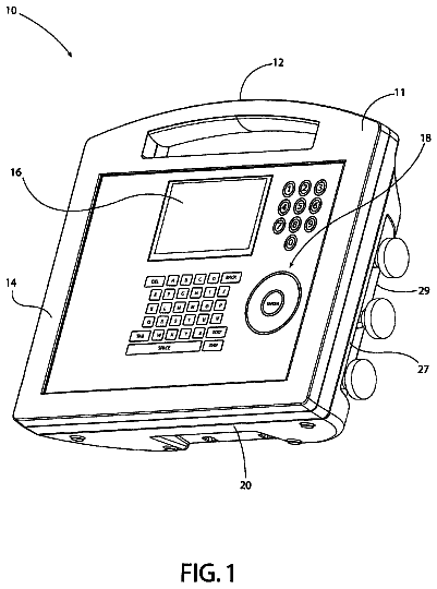
Combination tester
A tester that measures pressure includes at least one pressure input port, at least one transducer, GPS communications, and a controller.
US 9,967,034 B2 · Assignee: SUMITOMO ELECTRIC INDUSTRIES, LTD. · Inventors: Yuda; Shuitsu
Sheet 1 of 28 from the published document. All sheets in the USPTO PDF
There are provided an optical transceiver, an optical network unit, and an optical transceiver control method that control the operating state of the optical transceiver and reduce the number of terminals of the optical transceiver. An optical transceiver includes: a transmitting and receiving unit that transmits and receives optical signals and that has three or more states for transmission or reception of the optical signals, the states transitioning in sequence; a terminal for receiving a voltage or current as operation instruction information indicating in which one of the states operation is to be performed; and a determining unit for determining one of the states indicated by the operation instruction information, based on a magnitude of the voltage or current received by the terminal. The transmitting and receiving unit operates in the one of the states determined by the determining unit.
In recent years, the Internet has proliferated widely. Thus, users can access various information on sites run around the world and obtain the information. Accordingly, apparatuses capable of performing broadband access such as ADSL (Asymmetric Digital Subscriber Line) and FTTH (Fiber To The Home) have also been widely used at a rapid pace. IEEE Std 802.3ah (registered trademark)—2004 (Non-Patent Literature 1) discloses one system of a passive optical network (PON) which is medium-sharing communication where a plurality of optical network units (ONUs) perform data transmission with an optical line terminal (OLT) by sharing an optical communication line. Specifically, there are defined EPON (Ethernet (registered trademark) PON) where all pieces of information including user information passing through the PON and control information for managing and operating the PON are communicated in E
1 of 28 drawing sheets so far from the published document, cropped to the drawing. Every sheet is in the USPTO PDF.
What the patent claimed, word for word. All of it is now free to use.
The present invention relates to an optical transceiver, an optical network unit, and an optical transceiver control method, and more particularly to an optical transceiver, an optical network unit, and an optical transceiver control method that can perform power saving operation.
In recent years, the Internet has proliferated widely. Thus, users can access various information on sites run around the world and obtain the information. Accordingly, apparatuses capable of performing broadband access such as ADSL (Asymmetric Digital Subscriber Line) and FTTH (Fiber To The Home) have also been widely used at a rapid pace.
IEEE Std 802.3ah (registered trademark)—2004 (Non-Patent Literature 1) discloses one system of a passive optical network (PON) which is medium-sharing communication where a plurality of optical network units (ONUs) perform data transmission with an optical line terminal (OLT) by sharing an optical communication line. Specifically, there are defined EPON (Ethernet (registered trademark) PON) where all pieces of information including user information passing through the PON and control information for managing and operating the PON are communicated in Ethernet (registered trademark) frame format; and an access control protocol (MPCP (Multi-Point Control Protocol)) and an OAM (Operations Administration and Maintenance) protocol for EPON. By exchanging MPCP frames between the optical line terminal and the optical network units, joining, leaving, and upstream access multiple control of the optical network units, etc., are performed. In addition, Non-Patent Literature 1 describes a new-optical network unit registration method, a report indicating a bandwidth allocation request, and a gate indicating a transmission instruction, by MPCP messages.
Note that even in 10G-EPON which is standardized as IEEE 802.3av (registered trademark)—2009 as the next-generation technology of GE-PON (Giga Bit Ethernet (registered trademark) Passive Optical Network) which is EPON achieving a communication speed of 1 gigabit per second, i.e., EPON whose communication speed is equivalent to 10 gigabits per second, an access control protocol is premised on MPCP. CITATION LIST Non-Patent Literature
Non-Patent Literature 1; IEEE Std 802.3ah (registered trademark)—2004 SUMMARY OF INVENTION Technical Problem
Meanwhile, there is a demand for power saving of ONUs. Thus, there is also a need to achieve power saving of an optical transceiver for transmitting and receiving optical signals which is mounted on an ONU. For this, in the power saving operation of the ONU, it requires to appropriately control the optical transceiver. For example, a configuration is considered in which in order to control the operating state of the optical transceiver, i.e., whether to supply power to each circuit in the optical transceiver, a plurality of control signals are provided to the optical transceiver from the main body side of the ONU.
In addition, there is a demand for miniaturization of ONUs. Thus, there is also a need to achieve miniaturization of an optical transceiver. To achieve miniaturization of an optical transceiver, there is a need to reduce not only the size thereof but also, particularly, the number of connector terminals attached to the optical transceiver.
However, if a plurality of control signals are provided to the optical transceiver to allow the optical transceiver to perform power saving operation, then the number of terminals of the optical transceiver increases, resulting in going against miniaturization.
The present invention is made to solve the above-described problems, and an object of the present invention is to provide an optical transceiver, an optical network unit, and an optical transceiver control method that can control the operating state of the optical transceiver and achieve a reduction in the number of terminals of the optical transceiver. Solution to Problem
In order to solve the problems, an optical transceiver according to one aspect of the present invention includes: a transmitting and receiving unit that transmits and receives optical signals and that has three or more states for transmission or reception of the optical signals, the states transitioning in sequence; a terminal for receiving a voltage or current as operation instruction information indicating in which one of the states operation is to be performed; and a determining unit for determining one of the states indicated by the operation instruction information, based on a magnitude of the voltage or current received by the terminal, wherein the transmitting and receiving unit operates in the one of the states determined by the determining unit.
By such a configuration, for example, when the operating state of an optical transceiver operable in three states is controlled by two binary control signals, terminals for providing the control signals to the optical transceiver can be integrated into one. In addition, for example, when the operating state of an optical transceiver operable in four states is controlled by three binary control signals, terminals for providing the control signals to the optical transceiver can be integrated into one or two. Therefore, the operating state of the optical transceiver can be controlled and a reduction in the number of terminals of the optical transceiver can be achieved. In addition, since it does not take time to decode the control signals, a reduction in the response rate of the optical transceiver can be prevented.
Preferably, in the transmitting and receiving unit, a transmission-off state, a standby state, and a transmission-on state transition in sequence for transmission of the optical signals.
By such a configuration, a transition of three states of the transmitting unit in the optical transceiver can be controlled, and thus, the upstream frame transmission intervals of each optical network unit can be set to be shorter and the power saving operation of each optical network unit can be minutely set. Therefore, power saving of the optical transceiver can be achieved using a plurality of control signals, and a reduction in the number of terminals of the optical transceiver can be achieved.
More preferably, the transmitting and receiving unit includes: a light-emitting circuit including a light-emitting device; a modulation circuit for supplying a modulation current to the light-emitting device; a first power source that supplies power to the light-emitting circuit and is capable of controlling start and stop of the power supply; and a second power source that supplies power to the modulation circuit and is capable of controlling start and stop of the power supply, wherein in the transmission-off state, the first power source stops power supply to the light-emitting circuit and the second power source stops power supply to the modulation circuit, in the transmission-on state, the first power source supplies power to the light-emitting circuit and the second power source supplies power to the modulation circuit, and in the standby state, the first power source stops power supply to the light-emitting circuit and the second power source supplies power to the modulation circuit.
By such a configuration, a reduction in the number of terminals of the optical transceiver can be achieved and power saving control of each circuit in the transmitting unit in the optical transceiver can be appropriately performed.
More preferably, the transmission-off state, the standby state, and the transmission-on state transition in sequence in this order and in both directions, a voltage received by the terminal as operation instruction information indicating the standby state is an intermediate voltage between voltages received by the terminal as operation instruction information indicating the transmission-on state and the transmission-off state, or a current received by the terminal as operation instruction information indicating the standby state is an intermediate current between currents received by the terminal as operation instruction information indicating the transmission-on state and the transmission-off state.
By such a configuration, the amount of change in voltage or current received by the optical transceiver as operation instruction information, which results from a state transition of the optical transceiver can be reduced, enabling to improve the response rate of the optical transceiver.
Preferably, in the transmitting and receiving unit, a transmission/reception-off state in which transmission operation and reception operation of the optical signals are stopped, a transmission-off state in which transmission operation of the optical signals is stopped and reception operation of the optical signals is performed, a transmission standby state in which transmission of the optical signals is prepared and reception operation of the optical signals is performed, and a transmission/reception-on state in which transmission operation and reception operation of the optical signals are performed, transition in sequence.
By such a configuration, a transition of four states of the transmitting and receiving unit in the optical transceiver can be controlled, and thus, the upstream frame transmission intervals of each optical network unit can be set to be shorter and the power saving operation of each optical network unit can be minutely set. Therefore, power saving of the optical transceiver can be achieved using a plurality of control signals, and a reduction in the number of terminals of the optical transceiver can be achieved.
More preferably, the transmitting and receiving unit includes: a light-emitting circuit including a light-emitting device; a modulation circuit for supplying a modulation current to the light-emitting device; a light-receiving circuit including a light-receiving device; a first power source that supplies power to the light-emitting circuit and is capable of controlling start and stop of the power supply; a second power source that supplies power to the modulation circuit and is capable of controlling start and stop of the power supply; and a third power source that supplies power to the light-receiving circuit and is capable of controlling start and stop of the power supply, wherein in the transmission/reception-off state, the first power source stops power supply to the light-emitting circuit, the second power source stops power supply to the modulation circuit, and the third power source stops power supply to the light-receiving circuit, in the transmission-off state, the first power source stops power supply to the light-emitting circuit, the second power source stops power supply to the modulation circuit, and the third power source supplies power to the light-receiving circuit, in the transmission standby state, the first power source stops power supply to the light-emitting circuit, the second power source supplies power to the modulation circuit, and the third power source supplies power to the light-receiving circuit, and in the transmission/reception-on state, the first power source supplies power to the light-emitting circuit, the second power source supplies power to the modulation circuit, and the third power source supplies power to the light-receiving circuit.
By such a configuration, a reduction in the number of terminals of the optical transceiver can be achieved and power saving control of each circuit in the transmitting and receiving unit in the optical transceiver can be appropriately performed.
More preferably, the transmission/reception-off state, the transmission-off state, the transmission standby state, and the transmission/reception-on state transition in sequence in this order and in both directions, a voltage received by the terminal as operation instruction information indicating the transmission-off state is an intermediate voltage between voltages received by the terminal as operation instruction information indicating the transmission/reception-off state and the transmission standby state or the transmission/reception-on state, or a current received by the terminal as operation instruction information indicating the transmission-off state is an intermediate current between currents received by the terminal as operation instruction information indicating the transmission/reception-off state and the transmission standby state or the transmission/reception-on state.
By such a configuration, the amount of change in voltage or current received by the optical transceiver as operation instruction information, which results from a state transition of the optical transceiver can be reduced, enabling to improve the response rate of the optical transceiver.
In order to solve the problems, an optical network unit according to one aspect of the invention is for transmitting and receiving optical signals to/from an optical line terminal, wherein the optical network unit has: three or more states for transmission or reception of the optical signals, the states transitioning in sequence; and pieces of operation instruction information with which the states are associated in magnitude of a voltage or current such that the transition in sequence exhibits an increase or decrease in voltage or current, and the optical network unit includes: a control unit for determining in which one of the states an optical transceiver is allowed to operate, the optical transceiver performing transmission and reception of the optical signals; and an instructing unit for converting the state determined by the control unit into operation instruction information and providing the operation instruction information to the optical transceiver.
By such a configuration, for example, when the operating state of an optical transceiver operable in three states is controlled by two binary control signals, terminals for providing the control signals to the optical transceiver can be integrated into one. In addition, for example, when the operating state of an optical transceiver operable in four states is controlled by three binary control signals, terminals for providing the control signals to the optical transceiver can be integrated into one or two. Therefore, the operating state of the optical transceiver can be controlled and a reduction in the number of terminals of the optical transceiver can be achieved. In addition, since it does not take time to decode the control signals, a reduction in the response rate of the optical transceiver can be prevented.
Preferably, a transmission-off state, a standby state, and a transmission-on state transition in sequence for transmission of the optical signals.
By such a configuration, a transition of three states of the transmitting unit in the optical transceiver can be controlled, and thus, the upstream frame transmission intervals of each optical network unit can be set to be shorter and the power saving operation of each optical network unit can be minutely set. Therefore, power saving of the optical transceiver can be achieved using a plurality of control signals, and a reduction in the number of terminals of the optical transceiver can be achieved.
More preferably, the transmission-off state, the standby state, and the transmission-on state transition in sequence in this order and in both directions, and the instructing unit outputs: as operation instruction information indicating the standby state, an intermediate voltage between voltages outputted to the optical transceiver as operation instruction information indicating the transmission-on state and the transmission-off state, to the optical transceiver; or as operation instruction information indicating the standby state, an intermediate current between currents outputted to the optical transceiver as operation instruction information indicating the transmission-on state and the transmission-off state, to the optical transceiver.
By such a configuration, the amount of change in voltage or current received by the optical transceiver as operation instruction information, which results from a state transition of the optical transceiver can be reduced, enabling to improve the response rate of the optical transceiver.
Preferably, a transmission/reception-off state in which transmission operation and reception operation of the optical signals are stopped, a transmission-off state in which transmission operation of the optical signals is stopped and reception operation of the optical signals is performed, a transmission standby state in which transmission of the optical signals is prepared and reception operation of the optical signals is performed, and a transmission/reception-on state in which transmission operation and reception operation of the optical signals are performed, transition in sequence.
By such a configuration, a transition of four states of the transmitting and receiving unit in the optical transceiver can be controlled, and thus, the upstream frame transmission intervals of each optical network unit can be set to be shorter and the power saving operation of each optical network unit can be minutely set. Therefore, power saving of the optical transceiver can be achieved using a plurality of control signals, and a reduction in the number of terminals of the optical transceiver can be achieved.
More preferably, the transmission/reception-off state, the transmission-off state, the transmission standby state, and the transmission/reception-on state transition in sequence in this order and in both directions, and the instructing unit outputs: as operation instruction information indicating the transmission-off state, an intermediate voltage between voltages outputted to the optical transceiver as operation instruction information indicating the transmission/reception-off state and the transmission standby state or the transmission/reception-on state, to the optical transceiver; or as operation instruction information indicating the transmission-off state, an intermediate current between currents outputted to the optical transceiver as operation instruction information indicating the transmission/reception-off state and the transmission standby state or the transmission/reception-on state, to the optical transceiver.
By such a configuration, the amount of change in voltage or current received by the optical transceiver as operation instruction information, which results from a state transition of the optical transceiver can be reduced, enabling to improve the response rate of the optical transceiver.
In order to solve the problems, an optical transceiver control method according to one aspect of the invention, is the optical transceiver control method for an optical network unit that transmits and receives optical signals to/from an optical line terminal and that has three or more states for transmission or reception of the optical signals, the states transitioning in sequence, and has pieces of operation instruction information with which the states are associated in magnitude of a voltage or current such that the transition in sequence exhibits an increase or decrease in voltage or current, the method includes the steps of: determining in which one of the states an optical transceiver is allowed to operate, the optical transceiver performing transmission and reception of the optical signals; converting the determined state into operation instruction information and providing the operation instruction information to the optical transceiver; determining one of the states indicated by the operation instruction information, based on a magnitude of a voltage or current received by the optical transceiver as the operation instruction information; and allowing the optical transceiver to operate in the determined one of the states.
By such a configuration, for example, when the operating state of an optical transceiver operable in three states is controlled by two binary control signals, terminals for providing the control signals to the optical transceiver can be integrated into one. In addition, for example, when the operating state of an optical transceiver operable in four states is controlled by three binary control signals, terminals for providing the control signals to the optical transceiver can be integrated into one or two. Therefore, the operating state of the optical transceiver can be controlled and a reduction in the number of terminals of the optical transceiver can be achieved. In addition, since it does not take time to decode the control signals, a reduction in the response rate of the optical transceiver can be prevented. Advantageous Effects of Invention
According to the present invention, the operating state of an optical transceiver can be controlled and a reduction in the number of terminals of the optical transceiver can be achieved.
FIG. 1 is a diagram showing a configuration of a PON system according to a first embodiment of the present invention.
FIG. 2 is a diagram showing a configuration of an optical network unit in the PON system according to the first embodiment of the present invention.
FIG. 3 is a diagram showing a configuration of an optical transceiver in an optical network unit according to the first embodiment of the present invention.
FIG. 4 is a diagram showing a configuration of transmission of control signals to the optical transceiver in the optical network unit according to the first embodiment of the present invention.
FIG. 5 is a diagram showing the relationship of the logic levels of the control signals to the optical transceiver, the voltage at a control terminal, and the operating state of the optical transceiver, for the optical network unit according to the first embodiment of the present invention.
FIG. 6 is a diagram showing a variant of the configuration of transmission of control signals to the optical transceiver in the optical network unit according to the first embodiment of the present invention.
FIG. 7 is a diagram showing a variant of the configuration of transmission of control signals to the optical transceiver in the optical network unit according to the first embodiment of the present invention.
FIG. 8 is a diagram showing the relationship of the logic levels of the control signals to the optical transceiver, the voltage at the control terminal, and the operating state of the optical transceiver in the variant shown in FIG. 7 .
FIG. 9 is a diagram showing a variant of the configuration of transmission of control signals to the optical transceiver in the optical network unit according to the first embodiment of the present invention.
FIG. 10 is a diagram showing the relationship of the logic levels of the control signals to the optical transceiver, the voltage at the control terminal, and the operating state of the optical transceiver in the variant shown in FIG. 9 .
FIG. 11 is a diagram showing an example of the switching timing of an optical output and control signals for a burst transmitting unit in the optical transceiver according to the first embodiment of the present invention.
FIG. 12 is a diagram showing a configuration of transmission of control signals to the optical transceiver in the optical network unit according to the second embodiment of the present invention.
FIG. 13 is a diagram showing the relationship of the logic levels of the control signals to the optical transceiver, the voltage at a control terminal, and the operating state of the optical transceiver, for the optical network unit according to the second embodiment of the present invention.
FIG. 14 is a diagram showing a variant of the configuration of transmission of control signals to the optical transceiver in the optical network unit according to the second embodiment of the present invention.
FIG. 15 is a diagram showing a variant of the configuration of transmission of control signals to the optical transceiver in the optical network unit according to the second embodiment of the present invention.
FIG. 16 is a diagram showing the relationship of the logic levels of the control signals to the optical transceiver, the voltage at a control terminal, and the operating state of the optical transceiver, for the optical network unit according to the second embodiment of the present invention.
FIG. 17 is a diagram showing a variant of the configuration of transmission of control signals to the optical transceiver in the optical network unit according to the second embodiment of the present invention.
FIG. 18 is a diagram showing the relationship of the logic levels of the control signals to the optical transceiver, the voltage at a control terminal, and the operating state of the optical transceiver, for the optical network unit according to the second embodiment of the present invention.
FIG. 19 is a diagram showing the flow of data between an optical line terminal and an optical network unit in a PON system according to the second embodiment of the present invention, and the operating modes of the optical network unit.
FIG. 20 is a flowchart defining an operation procedure for when an optical network unit in the PON system according to the second embodiment of the present invention performs a power saving process.
FIG. 21 is a diagram showing a configuration of transmission of control signals to the optical transceiver in the optical network unit according to the third embodiment of the present invention.
FIG. 22 is a diagram showing the relationship of the logic levels of the control signals to the optical transceiver, the voltage at a control terminal, and the operating state of the optical transceiver, for the optical network unit according to the third embodiment of the present invention.
FIG. 23 is a diagram showing a variant of the configuration of transmission of control signals to the optical transceiver in the optical network unit according to the third embodiment of the present invention.
FIG. 24 is a diagram showing a variant of the configuration of transmission of control signals to the optical transceiver in the optical network unit according to the third embodiment of the present invention.
FIG. 25 is a diagram showing the relationship of the logic levels of the control signals to the optical transceiver, the voltage at the control terminal, and the operating state of the optical transceiver in the variant shown in FIG. 24 .
FIG. 26 is a diagram showing a variant of the configuration of transmission of control signals to the optical transceiver in the optical network unit according to the third embodiment of the present invention.
FIG. 27 is a diagram showing the relationship of the logic levels of the control signals to the optical transceiver, the voltage at the control terminal, and the operating state of the optical transceiver in the variant shown in FIG. 26 .
FIG. 28 is a flowchart defining an operation procedure for when each of the optical network units according to the first to third embodiments of the present invention controls its optical transceiver.
Embodiments of the present invention will be described below using the drawings. Note that the same or corresponding portions in the drawings are denoted by the same reference signs and description thereof is not repeated. First Embodiment Configuration and Basic Operation
FIG. 1 is a diagram showing a configuration of a PON system according to a first embodiment of the present invention.
Referring to FIG. 1 , a PON system 301 is, for example, 10G-EPON and includes optical network units 202 A, 202 B, 202 C, and 202 D, an optical line terminal 201 , and splitters SP 1 and SP 2 . The optical network units 202 A, 202 B, and 202 C and the optical line terminal 201 are connected to each other through the splitters SP 1 and SP 2 and an optical fiber OPTF, and transmit and receive optical signals to/from each other. The optical network unit 202 D and the optical line terminal 201 are connected to each other through the splitter SP 2 and the optical fiber OPTF, and transmit and receive optical signals to/from each other. In the PON system 301 , optical signals from the optical network units 202 A, 202 B, 202 C, and 202 D to the optical line terminal 201 are time-division multiplexed.
Here, the direction from the ONUs to an upper network is referred to as an upstream direction, and the direction from the upper network to the ONUs is referred to as a downstream direction.
FIG. 2 is a diagram showing a configuration of an optical network unit in the PON system according to the first embodiment of the present invention.
Referring to FIG. 2 , an optical network unit 202 includes an optical transceiver 21 , a PON reception processing unit 22 , a buffer memory 23 , a UN transmission processing unit 24 , a UNI (User Network Interface) port 25 , a UN reception processing unit 26 , a buffer memory 27 , a PON transmission processing unit 28 , and a control unit 29 .
The optical transceiver 21 is removable from the optical network unit 202 . The optical transceiver 21 operates by, for example, a power supply voltage supplied from the optical network unit 202 , with the optical transceiver 21 being mounted on the optical network unit 202 . The optical transceiver 21 receives a downstream optical signal transmitted from the optical line terminal 201 and converts the downstream optical signal into an electrical signal and then outputs the electrical signal.
The PON reception processing unit 22 reconstructs a frame from the electrical signal received from the optical transceiver 21 and sorts the frame into the control unit 29 or the UN transmission processing unit 24 , according to the type of the frame. Specifically, the PON reception processing unit 22 outputs a data frame to the UN transmission processing unit 24 via the buffer memory 23 , and outputs a control frame to the control unit 29 .
The control unit 29 generates a control frame including various types of control information and outputs the control frame to the UN transmission processing unit 24 .
The UN transmission processing unit 24 transmits, via the UNI port 25 , the data frame received from the PON reception processing unit 22 and the control frame received from the control unit 29 , to a user terminal such as a personal computer which is not shown.
The UN reception processing unit 26 outputs a data frame received from the user terminal via the UNI port 25 , to the PON transmission processing unit 28 via the buffer memory 27 , and outputs a control frame received from the user terminal via the UNI port 25 , to the control unit 29 .
The control unit 29 performs a home-side process pertaining to the control and management of a PON line between the optical line terminal 201 and the optical network unit 202 , such as MPCP and OAM. Specifically, by exchanging MPCP messages and OAM messages with the optical line terminal 201 connected to the PON line, various types of control such as access control are performed. The control unit 29 generates a control frame including various types of control information and outputs the control frame to the PON transmission processing unit 28 . In addition, the control unit 29 performs various types of setting processes for the respective units in the optical network unit 202 .
The PON transmission processing unit 28 outputs the data frame received from the UN reception processing unit 26 and the control frame received from the control unit 29 , to the optical transceiver 21 .
The optical transceiver 21 converts the data frame and control frame received from the PON transmission processing unit 28 , into an optical signal and transmits the optical signal to the optical line terminal 201 .
FIG. 3 is a diagram showing a configuration of an optical transceiver in an optical network unit according to the first embodiment of the present invention.
Referring to FIG. 3 , the optical transceiver 21 includes a burst transmitting unit 31 , a burst receiving unit 32 , a master I/F (interface) 69 , a CPU (Central Processing Unit) 70 , a slave I/F 71 , and a control register 72 . The burst transmitting unit 31 includes a transmission modulation circuit 74 and a light-emitting circuit 75 , as an electric circuit for transmitting optical signals. In addition, the burst transmitting unit 31 includes power sources 64 to 66 and a bias circuit 68 . The CPU 70 includes a memory unit 73 which is, for example, an EEPROM (Electrically Erasable Programmable Read Only Memory). The transmission modulation circuit 74 includes a prebuffer circuit 61 , an equalizer circuit 62 , an output buffer circuit 63 , and capacitors C 1 and C 2 . The prebuffer circuit 61 includes a resistor R. The light-emitting circuit 75 includes a light-emitting device LD and inductors L 1 and L 2 .
The burst receiving unit 32 includes a light-receiving device PD, a TIA (Transimpedance Amplifier) 81 , an LIA (Limiting Amplifier) 82 , a CDR (Clock and Data Recovery) 83 , an equalizer circuit 84 , an output buffer 85 , and capacitors C 3 to C 6 , as a light-receiving circuit which is an electric circuit for receiving optical signals. In addition, the burst receiving unit 32 includes power sources 86 to 90 .
In the burst transmitting unit 31 , the prebuffer circuit 61 receives, through the capacitors C 1 and C 2 , transmit data which is a data frame from the UN reception processing unit 26 and a control frame from the control unit 29 , and amplifies the transmit data and then outputs the amplified transmit data. For example, the prebuffer circuit 61 receives the transmit data through signal lines INP and INN, as balanced signals.
The equalizer circuit 62 performs waveform shaping, e.g., phase distortion correction, on the transmit data received from the prebuffer circuit 61 and outputs the transmit data.
The output buffer circuit 63 supplies modulation currents to the light-emitting circuit 75 , based on the transmit data received from the equalizer circuit 62 .
The light-emitting circuit 75 transmits an upstream optical signal to the optical line terminal 201 . In the light-emitting circuit 75 , the light-emitting device LD is connected through the inductor L 1 to a power supply node to which a power supply voltage Vdd 1 is supplied, and is connected through the inductor L 2 to the bias circuit 68 . The light-emitting device LD emits light based on a bias current supplied from the bias circuit 68 and the modulation currents supplied from the output buffer circuit 63 , and changes light emission intensity.
The power sources 64 to 66 supply, as power, for example, currents to the prebuffer circuit 61 , the equalizer circuit 62 , and the output buffer circuit 63 , respectively, and can control the start and stop of the power supply. More specifically, the power sources 64 to 66 switch whether to supply currents to the prebuffer circuit 61 , the equalizer circuit 62 , and the output buffer circuit 63 , based on a transmit disable signal received from the control unit 29 .
The bias circuit 68 supplies, as power, for example, a bias current to the light-emitting circuit 75 . In addition, the bias circuit 68 switches whether to supply a bias current to the light-emitting circuit 75 , based on the transmit disable signal and a burst enable signal which are received from the control unit 29 .
Specifically, the power sources 64 to 66 supply power to the prebuffer circuit 61 , the equalizer circuit 62 , and the output buffer circuit 63 when the transmit disable signal is deactivated, and stop the power supply when the transmit disable signal is activated.
The bias circuit 68 supplies power to the light-emitting circuit 75 when the transmit disable signal is deactivated and the burst enable signal is activated, and stops the power supply to the light-emitting circuit 75 otherwise.
The CPU 70 exchanges various types of data with the control unit 29 via, for example, an I2C bus including a signal line SCL and a signal line SDA.
The master I/F 69 provides an interface function between the CPU 70 and the I2C bus.
The slave I/F 71 provides an interface function between the CPU 70 and the control register 72 .
The CPU 70 writes various control data in the control register 72 through the slave I/F 71 .
The memory unit 73 in the CPU 70 stores the response time of each of the prebuffer circuit 61 , the equalizer circuit 62 , the output buffer circuit 63 , and the light-emitting circuit 75 , with respect to the start and stop of power supply. For example, the response time is the sum of a startup time from when each of the prebuffer circuit 61 , the equalizer circuit 62 , the output buffer circuit 63 , and the light-emitting circuit 75 receives power supply from its corresponding power source or the bias circuit 68 until starting operation, and a shutdown time from when the power supply is stopped until stopping the operation.
In the burst transmitting unit 31 , of the prebuffer circuit 61 , the equalizer circuit 62 , the output buffer circuit 63 , and the light-emitting circuit 75 , the prebuffer circuit 61 has the slowest response. The startup time of the prebuffer circuit 61 is a time constant τ of the capacitors C 1 and C 2 for AC coupling and the terminating resistor R.
The power source 66 changes the amount of current supplied to the output buffer circuit 63 , based on control data APC 1 written in the control register 72 .
The bias circuit 68 changes the amount of current supplied to the light-emitting circuit 75 , based on control data APC 2 written in the control register 72 .
In the burst receiving unit 32 , the light-receiving device PD converts an optical signal received from the optical line terminal 201 into a current and outputs the current.
The TIA 81 converts the current received from the light-receiving device PD into voltages and outputs the voltages to the LIA 82 via the capacitors C 3 and C 4 .
The LIA 82 binarizes the levels of the voltages received from the TIA 81 and outputs the binarized levels as receive data.
The CDR 83 reshapes the receive data received from the LIA 82 and extracts timing from the receive data and performs retiming on the receive data based on the extracted timing, thereby establishing synchronization with the optical line terminal 201 .
The equalizer circuit 84 performs waveform shaping, e.g., phase distortion correction, on the receive data received from the CDR 83 and outputs the receive data.
The output buffer 85 amplifies the receive data received from the equalizer circuit 84 and outputs the amplified receive data to the PON reception processing unit 22 through the capacitors C 5 and C 6 . For example, the output buffer 85 outputs the receive data through signal lines OUTP and OUTN, as balanced signals.
The power sources 86 to 90 supply, as power, for example, currents to the TIA 81 , the LIA 82 , the CDR 83 , the equalizer circuit 84 , and the output buffer 85 , respectively. In addition, the power sources 88 to 90 can control the start and stop of the power supply. More specifically, the power sources 88 to 90 switch whether to supply currents to the CDR 83 , the equalizer circuit 84 , the output buffer 85 , based on a receive disable signal received from the control unit 29 .
Specifically, the power sources 88 to 90 supply power to the CDR 83 , the equalizer circuit 84 , and the output buffer 85 when the receive disable signal is deactivated, and stop the power supply when the receive disable signal is activated.
Each of the power sources 64 , 65 , and 66 , the bias circuit 68 , and the power sources 88 , 89 , and 90 may be hereinafter simply referred to as a “power source”.
The description continues in the full USPTO document.
About 6,355 words. The USPTO PDF has it with every drawing.
Fees are due 3.5, 7.5 and 11.5 years after grant. This patent expired on May 8, 2026, so the fee marked "not paid" was the one that went unpaid.
OPTICAL TRANSCEIVER, OPTICAL NETWORK UNIT, AND OPTICAL TRANSCEIVER CONTROL METHOD
Filed Apr 2012 · published Aug 2013Optical transceiver, optical network unit, and optical transceiver control method
Filed Apr 2012 · granted May 2018Earlier publications, parents and continuations. None of them can still be enforced, or this patent would not be listed.
Prior art cited by the examiner or applicant. Useful when you check your own idea for novelty.
Everything on this page comes from the documents linked above.