The entire disclosure of Japanese Patent Application No. 2015-242405 filed on Dec. 11, 2015 including description, claims, drawings, and abstract are incorporated herein by reference in its entirety.
Background of the invention
Field of the Invention
The present invention relates to an electrophotographic photoreceptor.
Description of the Related Art
In recent years, it has become mainstream to use toner having a small particle size in an electrophotographic image forming apparatus as a demand for a high-definition and high-quality image has increased. Toner having a small particle has a great adhesivity to the surface of an electrophotographic photoreceptor (hereinafter, also referred to as the “photoreceptor”). Hence, it is required to increase the abutting pressure of the cleaning blade to the photoreceptor in order to realize high cleaning property, and as a result, the surface of the photoreceptor is worn by the repeated use of the photoreceptor in some cases.
As a means to decrease the adhesivity between the surface of the photoreceptor and the toner and to increase the cleaning property, it has been known to add a fluorine-based material such as fluorine-based fine particles or a fluorine-based lubricant to the protective layer of a photoreceptor. However, the hardness of the surface of the protective layer is likely to be insufficient when the amount of the fluorine-based material added is great.
In addition, a fluorine-based material is likely to migrate to the surface of the film of a coating material for protective layer in the coating material. For this reason, the fluorine-based material tends to be present only on the surface and in the vicinity thereof of the photoreceptor (protective layer) at a high concentration. Hence, in the case of using the photoreceptor in an image forming apparatus, high cleaning property is exhibited in the beginning but the cleaning property is insufficient in some cases when the surface of the photoreceptor is shaved in association with repeated use of the photoreceptor.
In the techniques for improving both the wear resistance and cleaning property of a photoreceptor, for example, a protective layer formed of the polymerized and cured product of a radically polymerizable composition containing a urethane acrylate having a perfluoropolyether moiety, a tri- or higher functional radically polymerizable monomer, and a radically polymerizable compound having a charge transport structure is known (for example, see JP 2012-128324 A).
In addition, in the techniques for maintaining both the toner releasing property and low wear property of the surface even after printing a great number of sheets, for example, a protective layer which contains perfluoropolyether and has a proportion of the number of fluorine atoms to the number of carbon atoms of 0.10 or more and 0.40 or less is known (for example, see JP 2015-028613 A).
In addition, in the techniques for enhancing the hardness and scratch resistance of the surface of a photoreceptor and the durability of the photoreceptor, a protective layer formed through polymerization and crosslinking of a polymerizable compound with a surface-treated metal oxide is known (for example, see JP 2012-078620 A).
However, even in the case of using the protective layers described in JP 2012-128324 A and JP 2015-028613 A, there is a case in which a decrease in properties such as wear resistance or scratch resistance due to the mechanical strength is observed when the content of the perfluoropolyether compound is high and high cleaning property is not sufficiently maintained when the photoreceptor is repeatedly used when the content of the perfluoropolyether compound is low. Hence, there is room for investigation in the photoreceptor of the related art from the viewpoint of sufficiently exerting the wear resistance, the scratch resistance, and the cleaning property.
Summary of the invention
An object of the present invention is to provide an electrophotographic photoreceptor which exhibits excellent wear resistance, scratch resistance, and cleaning property and can exert these properties over a long period of time.
To achieve the abovementioned object, according to an aspect, an electrophotographic photoreceptor reflecting one aspect of the present invention comprises: a conductive support; a photosensitive layer disposed on the conductive support; and a protective layer disposed on the photosensitive layer, wherein the protective layer is formed of a polymerized and cured product of a radically polymerizable composition containing a radically polymerizable monomer, a perfluoropolyether compound having a radically polymerizable group, and metal oxide fine particles having a radically polymerizable group.
Brief description of the drawings
The above and other objects, advantages and features of the present invention will become more fully understood from the detailed description given hereinbelow and the appended drawings which are given by way of illustration only, and thus are not intended as a definition of the limits of the present invention, and wherein:
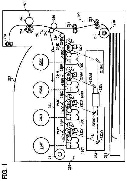
FIG. 1 is a diagram schematically showing an example of the configuration of an image forming apparatus according to an embodiment of the present invention.
Description of the preferred embodiments
Hereinafter, an embodiment of the present invention will be described with reference to the drawings. However, the scope of the invention is not limited to the illustrated examples.
The electrophotographic photoreceptor (photoreceptor) according to the present embodiment has a conductive support, a photosensitive layer disposed on the conductive support, and a protective layer disposed on the photosensitive layer.
The conductive support is a member which can support the photosensitive layer and exhibits conductivity. Examples of the conductive support may include a metal drum or sheet, a plastic film having a laminated metal foil, a plastic film having a deposited film of a conductive material, a metal member or a plastic film having a conductive layer formed by applying a coating material composed of a conductive material or the conductive material and a binder resin, and paper. Examples of the metal may include aluminum, copper, chromium, nickel, zinc, and stainless steel, and examples of the conductive material may include the metals, indium oxide, and tin oxide.
The photosensitive layer is a layer for forming an electrostatic latent image of a desired image on the surface of the photoreceptor by exposure to be described later. The photosensitive layer may be a single layer or may be constituted by a plurality of layers laminated. Examples of the photosensitive layer may include a single layer containing a charge transporting compound and a charge generating compound and a laminate of a charge transport layer containing a charge transporting compound and a charge generating layer containing a charge generating compound.
The protective layer is a layer which protects the photosensitive layer and constitutes the surface of the photoreceptor while being disposed on the photosensitive layer. The protective layer is formed of a polymerized and cured product of a radically polymerizable composition containing a radically polymerizable monomer, a perfluoropolyether compound having a radically polymerizable group, and metal oxide fine particles having a radically polymerizable group. In other words, the protective layer is constituted by an integral polymer obtained through radical polymerization of a radically polymerizable monomer, and a perfluoropolyether compound and metal oxide fine particles are dispersed in the protective layer. The perfluoropolyether compound and the metal oxide fine particles are both bonded to the polymer by a covalent bond through radical polymerization.
In addition, the photoreceptor may further include another configuration other than the conductive support and the photosensitive layer in a range in which the effect according to the present embodiment is obtained. Examples of another configuration may include an intermediate layer. The intermediate layer is, for example, a layer that is disposed between the conductive support and the photosensitive layer and has a barrier function and an adhesion function.
The photoreceptor can be configured in the same manner as a known organic photoreceptor except the layer constituting the surface thereof, and for example, it can be configured so that the portions other than the protective layer are the same as those in the photoreceptor described in JP 2012-078620 A. In addition, the protective layer can also be configured as described in JP 2012-078620 A except that the material is different.
The protective layer is a polymerized and cured product of a radically polymerizable composition as described above, and the radically polymerizable composition contains a radically polymerizable monomer, a perfluoropolyether compound having a radically polymerizable group, and metal oxide fine particles having a radically polymerizable group. These may all be one kind or more kinds.
[Radically Polymerizable Monomer]
The radically polymerizable monomer is a compound which has a radically polymerizable group and forms a resin to be generally used as a binder resin of a photoreceptor through radical polymerization (curing) as the radically polymerizable monomer is irradiated with an active ray such as ultraviolet light, visible light, or an electron beam or energy is applied thereto by heating or the like. Examples of the radically polymerizable monomer may include a styrene-based monomer, an acrylic monomer, a methacrylic monomer, a vinyl toluene-based monomer, a vinyl acetate-based monomer, and an N-vinyl pyrrolidone-based monomer, and examples of the binder resin may include polystyrene and polyacrylate.
The radically polymerizable group is a group which has a carbon-carbon double bond and is radically polymerizable. The radically polymerizable group is even more preferably an acryloyl group (CH.sub.2═CHCO—) or a methacryloyl group (CH.sub.2═C(CH.sub.3)CO—) from the viewpoint of being curable with a small amount of light or in a short time.
Specific examples of the radically polymerizable monomer may include the following compounds M1 to M15. In the following formulas, R represents an acryloyl group, R′ represents a methacryloyl group.
##str00001## ##str00002##
The radically polymerizable monomer compounds are known and can be available as commercial products as well. The radically polymerizable monomer is preferably a compound having 3 or more radically polymerizable groups from the viewpoint of forming a highly hard protective layer having a high crosslinking density.
[Perfluoropolyether Compound Having Radically Polymerizable Group]
The perfluoropolyether compound (hereinafter, also referred to as “PFPE”) in the perfluoropolyether compound having a radically polymerizable group (hereinafter, also referred to as the “radically polymerizable PFPE”) is an oligomer or polymer having perfluoroalkylene ether as a repeating unit. Examples of the structure of the perfluoroalkylene ether repeating unit may include structures of perfluoromethylene ether, perfluoroethylene ether, and perfluoropropylene ether repeating units. Among them, it is preferable that the perfluoropolyether has a repeating structural unit 1 represented by the following formula (a) or a repeating structural unit 2 represented by the following formula (b).
##str00003##
In a case in which the PFPE has the repeating structural unit 1 or the repeating structural unit 2 , the number of repetitions m of the repeating structural unit 1 and the number of repetitions n of the repeating structural unit 2 are each an integer 0 or more, and they are m+n≥1.
In addition, in a case in which the PFPE has both of the repeating structural unit 1 and the repeating structural unit 2 , the repeating structural unit 1 and the repeating structural unit 2 may form a block copolymer structure or a random copolymer structure.
The weight average molecular weight Mw of the PFPE is preferably 100 or more and 8,000 or less and more preferably 500 or more and 5,000 or less.
The number of the radically polymerizable groups belonging to the radically polymerizable PFPE is 1 or more and preferably 2 or more. In a case in which the radically polymerizable PFPE has two or more radically polymerizable groups, the position of the radically polymerizable groups in the PFPE may be one terminal or both terminals and the two or more radically polymerizable groups may be bonded to one terminal or both terminals.
Among them, the radically polymerizable PFPE having 4 or more radically polymerizable groups has more reactive sites with the radically polymerizable monomer and radically polymerizable metal oxide fine particles to be described later. Hence, the radically polymerizable PFPE having 4 or more radically polymerizable groups is even more preferable from the viewpoint of enhancing the wear resistance and cleaning property of the photoreceptor.
The radically polymerizable group is a group which has a carbon-carbon double bond and is radically polymerizable as that of the radically polymerizable monomer. The radically polymerizable group of the radically polymerizable PFPE may be the same as or different from that of the radically polymerizable monomer. In addition, a plurality of radically polymerizable groups belonging to the radically polymerizable PFPE may also be the same as or different from one another. The radically polymerizable functional group is even more preferably an acryloyl group or a methacryloyl group.
Examples of the PFPE having an acryloyl group or a methacryloyl group may include the Fluorolink AD1700, MD500, MD700, 5101X, and 5113X and the Fomblin MT70 (“FLUOROLINK” and “FOMBLIN” are both registered trademarks of the company) manufactured by Solvay Specialty Polymers, the OPTOOL DAC manufactured by DAIKIN INDUSTRIES, LTD., and the KY-1203 manufactured by Shin-Etsu Chemical Co., Ltd.
In addition, the radically polymerizable PFPE can be appropriately synthesized by using a PFPE having a hydroxyl group or a carboxyl group at the terminal as a starting material and substituting these substituents or deriving from these substituents, or such synthetic products may be used.
Examples of the PFPE having a hydroxyl group at the terminal may include the Fomblin D2, Fluorolink D4000, Fluorolink EtOH, 5158X, and 5147X, and Fomblin Z-tetraol manufactured by Solvay Specialty Polymers and the Demnum-SA manufactured by DAIKIN INDUSTRIES, LTD. Examples of the PFPE having a carboxyl group at the terminal may include the Fomblin ZDIZAC4000 manufactured by Solvay Specialty Polymers and the Demnum-SH manufactured by DAIKIN INDUSTRIES, LTD.
Specific examples of the PFPE having an acryloyl group or a methacryloyl group may include the following compounds P-1 to P-9. In the following formulas, X represents an acryloyl group (A) or a methacryloyl group (M). In addition, the term “p” in the compound P-2 independently represents from 1 to 10.
Incidentally, the following compounds may be more specifically indicated by adding A in a case in which X is an acryloyl group and M in a case in which X is a methacryloyl group to the symbol of the compounds. For example, the following compound P-1 in which X is an acryloyl group is denoted as “P-1A” and the following compound P-1 in which X is a methacryloyl group is denoted as “P-1M”.
##str00004##
Hereinafter, a specific example of the method for synthesizing the radically polymerizable PFPE is presented. Synthetic Example 1: Synthesis of P-2M
Mixed are 17 parts by mass of the Fluorolink E10H (manufactured by Solvay Specialty Polymers, average molecular weight: 1700) that is a perfluoropolyether compound having a hydroxyl group at both terminals and is represented by the following formula P-S1, 3 parts by mass of triethylamine, 10 parts by mass of diisopropyl ether, and 0.006 part by mass of p-methoxyphenol of a polymerization inhibitor, stirring of the mixture is started in an air stream. While keeping the temperature of the mixture at 10° C., 3.1 parts by mass of methacryloyl chloride is added thereto dropwise over 2 hours. After the dropwise addition is completed, the mixture thus obtained is stirred for 1 hour while keeping it at 10° C., subsequently the reaction mixture is heated to 30° C., stirred for 1 hour at 30° C., further heated to 50° C., and stirred for 10 hours at 50° C. to conduct the reaction. Subsequently, 72 parts by mass of diisopropyl ether is added to the reaction mixture thus obtained, and the diisopropyl ether phase is washed with water three times. Subsequently, the diisopropyl ether phase is dried over magnesium sulfate, and the solvent is distilled off therefrom. P-2M of a radically polymerizable PFPE is obtained in this manner (yield: 17.1 parts by mass).
##STR00005## Synthetic Example 2: Synthesis of P-3M
Synthesis of Intermediate (I)
Mixed are 18.5 parts by mass of the Fomblin ZDIAC4000 (manufactured by Solvay Specialty Polymers, average molecular weight: 3700) that is a perfluoropolyether compound having a carboxyl group at both terminals and represented by the following formula P-S2, 20 parts by mass of thionyl chloride, and 2 drops of N,N-dimethylformamide, the mixture is heated and refluxed for 4 hours. Excess thionyl chloride is distilled off from the reaction mixture thus obtained, thereby obtaining 18.6 parts by mass of an intermediate (I).
Synthesis of P-3M
In 50 parts by mass of dichloroethane, 2.3 parts by mass of glycerol dimethacrylate, 0.8 part by mass of pyridine, and 0.006 part by mass of p-methoxyphenol of a polymerization inhibitor are dissolved, 18.6 parts by mass of the intermediate (I) is added to the solution thus obtained. The mixture thus obtained is stirred for the night at room temperature as it is, subsequently water is added thereto to separate the dichloroethane phase. Thereafter, the dichloroethane phase is washed with water, and the solvent is distilled off therefrom. P-3M of a radically polymerizable PFPE is obtained in this manner (yield: 20.2 parts by mass).
##STR00006## Synthetic Example 3: Synthesis of P-6A
Mixed are 20 parts by mass of the Fomblin Z-tetraol (manufactured by Solvay Specialty Polymers) that is a perfluoropolyether compound having a hydroxyl group at both terminals and represented by the following formula P-S3, 0.01 part by mass of p-methoxyphenol of a polymerization inhibitor, 0.01 part by mass of dibutyltin dilaurate of a urethanated catalyst, and 20 parts by mass of methyl ethyl ketone, the mixture is stirred in an air stream and heated to 80° C. Subsequently, 5.7 parts by mass of 2-(acryloyloxy)ethyl isocyanate is added to the mixture in a divided manner while paying attention to heat generation. Subsequently, the mixture is stirred for 10 hours at 80° to conduct the reaction. The solvent is distilled off from the mixture after the disappearance of the absorption peak in the vicinity of 2360 cm.sup.−1 attributed to the isocyanate group is confirmed through the IR spectrum measurement. P-6A of a radically polymerizable PFPE is obtained in this manner (yield: 25.6 parts by mass).
##str00007##
The other exemplified compounds among P-1 to P-9 above can be synthesized in the same manner by any of the following methods.
1) A method to subject (meth)acryloyl chloride to an esterification reaction with a perfluoropolyether having a hydroxyl group at the terminal by dehydrochlorination.
2) A method to subject an isocyanate compound having a (meth)acryloyl group to an urethanization reaction with a perfluoropolyether having a hydroxyl group at the terminal.
3) A method to obtain an acid halide of a perfluoropolyether compound having a carboxyl group at the terminal by an ordinary method and to subject a compound having a (meth)acryloyl group and a hydroxyl group to an esterification reaction with the acid halide.
With regard to the content of the radically polymerizable PFPE in the radically polymerizable composition, the cleaning property of the photoreceptor is insufficient when it is too low and the wear resistance and scratch resistance of the photoreceptor are insufficient in some cases when it is too high. The content of the radically polymerizable PFPE in the radically polymerizable composition is preferably 10 parts by mass or more and more preferably 20 parts by mass or more with respect to 100 parts by mass of the radically polymerizable monomer from the viewpoint of sufficiently exerting the cleaning property. In addition, the content is preferably 100 parts by mass or less and more preferably 70 parts by mass or less from the viewpoint of sufficiently exerting the wear resistance and the scratch resistance.
[Metal Oxide Fine Particles Having Radically Polymerizable Group]
The metal oxide fine particles having a radically polymerizable group (hereinafter, also referred to as the “radically polymerizable metal oxide fine particles”) are metal oxide fine particles supporting a component containing a radically polymerizable group on the surface. Supporting of a component containing a radically polymerizable group on the surface of the metal oxide fine particles may be physical supporting or supporting by a chemical bond. The radically polymerizable group may be one kind or more kinds and a plurality of radically polymerizable groups may be the same as or different from one another. The radically polymerizable metal oxide fine particles have, for example, metal oxide fine particles, a surface treatment agent residue that is chemically bonded to the surface thereof, and the radically polymerizable group contained in the surface treatment agent residue, and in the protective layer, the metal oxide fine particles are present in a state of being chemically bonded to the integral polymer constituting the protective layer via the surface treatment agent residue on the surface thereof. Incidentally, the surface treatment agent residue is, for example, a molecular structure that is chemically bonded to the surface of the metal oxide fine particles and a moiety derived from the surface treatment agent.
The metal in the metal oxide fine particles includes a transition metal as well. The metal oxide fine particles may also be one kind or more kinds, and they may be the same kind as or different kinds from one another. Examples of the metal oxide in the metal oxide fine particles may include silica (silicon oxide), magnesium oxide, zinc oxide, lead oxide, alumina (aluminum oxide), tin oxide, tantalum oxide, indium oxide, bismuth oxide, yttrium oxide, cobalt oxide, copper oxide, manganese oxide, selenium oxide, iron oxide, zirconium oxide, germanium oxide, titanium dioxide, niobium oxide, molybdenum oxide, vanadium oxide, and copper aluminum oxide. Among them, the metal oxide is preferably alumina (Al.sub.2O.sub.3), tin oxide (SnO.sub.2), titanium dioxide (TiO.sub.2), and copper aluminum composite oxide (CuAlO.sub.2).
The number average primary particle size of the metal oxide fine particles is preferably in a range of from 1 to 300 nm. It is even more preferably from 3 to 100 nm. The number average primary particle size of the metal oxide fine particles may be the catalog value or can be determined as follows. In other words, a photograph that is enlarged by 10000-fold and taken by a scanning electron microscope (manufactured by JEOL Ltd.) is scanned by a scanner, the images of 300 particles taken from the photographic image thus obtained except the aggregated particles are randomly subjected to the binarization processing using the automatic image processing and analysis system “Luzex AP” (developed by Nireco Corporation, “LUZEX” is a registered trademark of the company, software Ver. 1.32), the Feret's diameters in the horizontal direction of the respective particle images are calculated, and the average value thereof is calculated and adopted as the number average primary particle size. Here, the Feret's diameter in the horizontal direction refers to the length of a side parallel to the x axis of the bounding rectangle when the particle image is subjected to the binarization processing.
Supporting of the component containing a radically polymerizable group on the surface of the metal oxide fine particles can be conducted by a known surface treatment technique for metal oxide fine particles. For example, the supporting can be conducted by a known surface treatment method using a surface treatment agent for metal oxide fine particles as described in JP 2012-078620 A.
The surface treating agent has a radically polymerizable group and a surface treating group. The surface treatment agent may be one kind or more kinds. The surface treating group is a functional group exhibiting reactivity to a polar group such as a hydroxyl group present on the surface of the metal oxide fine particles. The radically polymerizable group is a group which has a carbon-carbon double bond and is radically polymerizable as that of the radically polymerizable monomer or radically polymerizable PFPE, and examples thereof may include a vinyl group, an acrylic group, and a methacrylic group.
The surface treatment agent is preferably a silane coupling agent having the radically polymerizable group, and examples thereof may include the following compounds S-1 to S-36. CH.sub.2═CHSi(CH.sub.3)(OCH.sub.3).sub.2 S-1: CH.sub.2═CHSi(OCH.sub.3).sub.3 S-2: CH.sub.2═CHSiCl.sub.3 S-3: CH.sub.2═CHCOO(CH.sub.2).sub.2Si(CH.sub.3)(OCH.sub.3).sub.2 S-4: CH.sub.2═CHCOO(CH.sub.2).sub.2Si(OCH.sub.3).sub.3 S-5: CH.sub.2═CHCOO(CH.sub.2).sub.2Si(OC.sub.2H.sub.5)(OCH.sub.3).sub.2 S-6: CH.sub.2═CHCOO(CH.sub.2).sub.3Si(OCH.sub.3).sub.3 S-7: CH.sub.2═CHCOO(CH.sub.2).sub.2Si(CH.sub.3)Cl.sub.2 S-8: CH.sub.2═CHCOO(CH.sub.2).sub.2SiCl.sub.3 S-9: CH.sub.2═CHCOO(CH.sub.2).sub.3Si(CH.sub.3)Cl.sub.2 S-10: CH.sub.2═CHCOO(CH.sub.2).sub.3SiCl.sub.3 S-11: CH.sub.2═C(CH.sub.3)COO(CH.sub.2).sub.2Si(CH.sub.3)(OCH.sub.3).sub.2 S-12: CH.sub.2═C(CH.sub.3)COO(CH.sub.2).sub.2Si(OCH.sub.3).sub.3 S-13: CH.sub.2═C(CH.sub.3)COO(CH.sub.2).sub.3Si(CH.sub.3)(OCH.sub.3).sub.2 S-14: CH.sub.2═C(CH.sub.3)COO(CH.sub.2).sub.3Si(OCH.sub.3).sub.3 S-15: CH.sub.2═C(CH.sub.3)COO(CH.sub.2).sub.2Si(CH.sub.3)Cl.sub.2 S-16: CH.sub.2═C(CH.sub.3)COO(CH.sub.2).sub.2SiCl.sub.3 S-17: CH.sub.2═C(CH.sub.3)COO(CH.sub.2).sub.3Si(CH.sub.3)Cl.sub.2 S-18: CH.sub.2═C(CH.sub.3)COO(CH.sub.2).sub.3SiCl.sub.3 S-19: CH.sub.2═CHSi(C.sub.2H.sub.5)(OCH.sub.3).sub.2 S-20: CH.sub.2═C(CH.sub.3)Si(OCH.sub.3).sub.3 S-21: CH.sub.2═C(CH.sub.3)Si(OC.sub.2H.sub.5).sub.3 S-22: CH.sub.2═CHSi(OCH.sub.3).sub.3 S-23: CH.sub.2═C(CH.sub.3)Si(CH.sub.3)(OCH.sub.3).sub.2 S-24: CH.sub.2═CHSi(CH.sub.3)Cl.sub.2 S-25: CH.sub.2═CHCOOSi(OCH.sub.3).sub.3 S-26: CH.sub.2═CHCOOSi(OC.sub.2H.sub.5).sub.3 S-27: CH.sub.2═C(CH.sub.3)COOSi(OCH.sub.3).sub.3 S-28: CH.sub.2═C(CH.sub.3)COOSi(OC.sub.2H.sub.5).sub.3 S-29: CH.sub.2═C(CH.sub.3)COO(CH.sub.2).sub.3Si(OC.sub.2H.sub.5).sub.3 S-30: CH.sub.2═CHCOO(CH.sub.2).sub.2Si(CH.sub.3).sub.2(OCH.sub.3) S-31: CH.sub.2═CHCOO(CH.sub.2).sub.2Si(CH.sub.3)(OCOCH.sub.3).sub.2 S-32: CH.sub.2═CHCOO(CH.sub.2).sub.2Si(CH.sub.3)(ONHCH.sub.3).sub.2 S-33: CH.sub.2═CHCOO(CH.sub.2).sub.2Si(CH.sub.3)(OC.sub.6H.sub.5).sub.2 S-34: CH.sub.2═CHCOO(CH.sub.2).sub.2Si(C.sub.10H.sub.21)(OCH.sub.3).sub.2 S-35: CH.sub.2═CHCOO(CH.sub.2).sub.2Si(CH.sub.2C.sub.6H.sub.5)(OCH.sub.3).sub.2 S-36:
With regard to the content of the radically polymerizable metal oxide fine particles in the radically polymerizable composition, the wear resistance and scratch resistance of the photoreceptor are insufficient in some cases when the content is too low. In addition, the content of PFPE in the protective layer is relatively low when the content is too high, and as a result, the cleaning property of the photoreceptor is insufficient in some cases. The content of the radically polymerizable metal oxide fine particles in the radically polymerizable composition is preferably 30 parts by mass or more with respect to 100 parts by mass of the sum of the radically polymerizable monomer and the radically polymerizable PFPE from the viewpoint of sufficiently exerting the mechanical strength of the protective layer and also realizing a proper electric resistance. In addition, the content of the radically polymerizable metal oxide fine particles in the radically polymerizable composition is preferably 100 parts by mass or less from the viewpoint of sufficiently exerting the cleaning property.
The photoreceptor can be manufactured by a known method for manufacturing a photoreceptor except that the radically polymerizable composition is used in the coating material for protective layer. For example, the photoreceptor can be manufactured by a method including a step of applying a coating material for protective layer containing the radically polymerizable composition on the surface of a photosensitive layer formed on a conductive support and a step of radically polymerizing the radically polymerizable group in the coating material for protective layer by irradiating the applied coating material for protective layer with an active ray or heating the applied coating material for protective layer.
The coating material for protective layer may further contain other components other than the radically polymerizable composition in a range in which the effect of the present embodiment is obtained. Examples of such other components may include a solvent and a polymerization initiator.
The solvents may be one kind or more kinds. Examples of such a solvent may include methanol, ethanol, n-propyl alcohol, isopropyl alcohol, n-butanol, t-butanol, sec-butanol, benzyl alcohol, toluene, xylene, methyl ethyl ketone, cyclohexane, ethyl acetate, butyl acetate, methyl cellosolve, ethyl cellosolve, tetrahydrofuran, 1,3-dioxane, 1,3-dioxolane, pyridine, and diethylamine.
The polymerization initiator may be one kind or more kinds. The polymerization initiator can be appropriately selected from known polymerization initiators depending on the manufacturing process of the protective layer. Examples of the polymerization initiator may include a photopolymerization initiator, a thermal polymerization initiator, and a polymerization initiator capable of initiating polymerization by both of light and heat.
Examples of the polymerization initiator may include an azo compound such as 2,2′-azobisisobutyronitrile, 2,2′-azobis(2,4-dimethylazobisvaleronitrile), or 2,2′-azobis(2-methylbutyronitrile) and a peroxide such as benzoyl peroxide (BPO), di-tert-butyl hydroperoxide, tert-butyl hydroperoxide, chlorobenzoyl peroxide, dichlorobenzoyl peroxide, bromomethylbenzoyl peroxide, or lauroyl peroxide.
In addition, examples of the polymerization initiator may include an acetophenone-based or ketal-based photopolymerization initiator, and examples thereof may include diethoxyacetophenone, 2,2-dimethoxy-1,2-diphenylethane-1-one, 1-hydroxycyclohexyl phenyl ketone, 4-(2-hydroxyethoxy)phenyl-(2-hydroxy-2-propyl) ketone (12), 2-benzyl-2-dimethylamino-1-(4-morpholinophenyl)butanone-1 (Irgacure 369: manufactured by BASF Japan, “IRGACURE” is a registered trademark of BASF), 2-hydroxy-2-methyl-1-phenylpropan-1-one, 2-methyl-2-morpholino(4-methylthiophenyl)propan-1-one, and 1-phenyl-1,2-propanedione-2-(o-ethoxycarbonyl)oxime.
In addition, examples of the polymerization initiator may include a benzoin ether-based photopolymerization initiator such as benzoin, benzoin methyl ether, benzoin ethyl ether, benzoin isobutyl ether, or benzoin isopropyl ether, and a benzophenone-based photopolymerization initiator such as benzophenone, 4-hydroxybenzophenone, methyl o-benzoylbenzoate, 2-benzoylnaphthalene, 4-benzoylbiphenyl, 4-benzoyl phenyl ether, acrylated benzophenone, or 1,4-benzoylbenzene.
In addition, examples of the polymerization initiator may include a thioxanthone-based photopolymerization initiator such as 2-isopropylthioxanthone, 2-chlorothioxanthone, 2,4-dimethylthioxanthone, 2,4-diethylthioxanthone, or 2,4-dichlorothioxanthone.
In addition, examples of the polymerization initiator may include ethyl anthraquinone, 2,4,6-trimethylbenzoyldiphenylphosphine oxide, 2,4,6-trimethylbenzoylphenylethoxyphosphine oxide, bis(2,4,6-trimethylbenzoyl)phenylphosphine oxide, bis(2,4-dimethoxybenzoyl)-2,4,4-trimethylpentylphosphine oxide, methylphenyl glyoxylate, 9,10-phenanthrene, an acridine compound, a triazine compound, and an imidazole compound.
In addition, the photopolymerization initiator may be concurrently used with a photopolymerization promoter having a photopolymerization promoting effect. Examples of the photopolymerization promoter may include triethanolamine, methyldiethanolamine, ethyl 4-dimethylaminobenzoate, isoamyl 4-dimethylaminobenzoate, (2-dimethylamino)ethyl benzoate, and 4,4-dimethylaminobenzophenone.
The polymerization initiator is preferably a photopolymerization initiator, and for example, an alkylphenone-based compound and a phosphine oxide-based compound are preferable, a polymerization initiator having an α-hydroxyacetophenone structure or a polymerization initiator having an acylphosphine oxide structure is more preferable.
The content of the polymerization initiator in the radically polymerizable composition is preferably from 0.1 to 40 parts by mass and more preferably from 0.5 to 20 parts by mass with respect to 100 parts by mass of the radically polymerizable monomer.
In the protective layer, the radically polymerizable monomer, the radically polymerizable PFPE, and the radically polymerizable metal oxide fine particles constitute an integral polymer (polymerized and cured product) which forms the protective layer. It is possible to confirm that the polymerized and cured product is a polymer of the radically polymerizable monomer, the radically polymerizable PFPE, and the radically polymerizable metal oxide fine particles by analyzing the polymerized and cured product by a by known instrumental analysis technique such as pyrolysis GC-MS, nuclear magnetic resonance (NMR), Fourier transform infrared spectroscopy (FT-IR), or elemental analysis.
The radically polymerizable monomer, the radically polymerizable PFPE, and the radically polymerizable metal oxide fine particles all have a radically polymerizable group. Hence, these components exhibit high compatibility with one another in the radically polymerizable composition. Consequently, the radically polymerizable PFPE and the radically polymerizable metal oxide fine particles are both uniformly dispersed in the radically polymerizable composition. As a result, the PFPE and the metal oxide fine particles are present in the protective layer to be uniformly dispersed in both the plane direction and the thickness direction thereof as well.
In the protective layer, the respective radically polymerizable groups of the radically polymerizable monomer, the radically polymerizable PFPE, and the radically polymerizable metal oxide fine particles react with one another to form a crosslinked structure. Hence, a highly strong protective layer exhibiting sufficient wear resistance is obtained even when the content of PFPE is high to some extent.
Furthermore, high cleaning property of the protective layer is maintained over a long period of time. This is believed to be due to the following reasons. In other words, the PFPE is present in the protective layer in a state of being bonded with the metal oxide fine particles as well. Hence, the PFPE is likely to exist by being dispersed throughout the protective layer. In this manner, the PFPE and the metal oxide fine particles are present in the protective layer by being dispersed in both directions of the plane direction and the thickness direction of the protective layer, and thus the PFPE is present on the surface of the protective layer in an amount enough to maintain the cleaning property even when the protective layer is worn away.
Furthermore, the bonding sites of the radically polymerizable monomer and the radically polymerizable metal oxide particles with the PFPE increase when the radically polymerizable PFPE has 4 or more radically polymerizable groups. Hence, a protective layer of which even higher wear resistance and higher cleaning property last is obtained.
The photoreceptor is used as an organic photoreceptor in an electrophotographic image forming apparatus. For example, the image forming apparatus includes the photoreceptor, a charging device for charging the surface of the photoreceptor, an exposure device for forming an electrostatic latent image by irradiating the charged surface of the photoreceptor with light, a developing device for forming a toner image by supplying toner to the photoreceptor on which an electrostatic latent image is formed, a transfer device for transferring the toner image on the surface of the photoreceptor to a recording medium, and a cleaning device for removing the toner remaining on the surface of the photoreceptor from which the toner image has been transferred to the recording medium.
In addition, the photoreceptor is applied to an image forming method in which a toner image corresponding to an electrostatic latent image is formed on the surface of the photoreceptor by supplying the toner to the surface of the photoreceptor on which the electrostatic latent image is formed, the toner image is transferred from the surface of the photoreceptor to a recording medium, and the toner remaining on the surface of the photoreceptor is removed by using a cleaning device. The image forming method is performed, for example, by using the image forming apparatus described above.
FIG. 1 is a diagram schematically showing an example of the configuration of an image forming apparatus having the photoreceptor. An image forming apparatus 100 shown in FIG. 1 includes an image reading section 110 , an image processing section 30 , an image forming section 40 , a sheet conveying section 50 , and a fixing device 60 .
The image forming section 40 includes image forming units 41 Y, 41 M, 41 C, and 41 K which form an image with the respective color toners Y (yellow), M (magenta), C (cyan), and K (black). These all have the same configuration except the toner to be accommodated, and hereinafter, the symbol representing the color is omitted in some cases. The image forming section 40 further includes an intermediate transfer unit 42 and a secondary transfer unit 43 . These correspond to a transfer device.
The image forming unit 41 includes an exposure device 411 , a developing device 412 , the photoreceptor described above 413 , a charging device 414 , and a drum cleaning device 415 . The charging device 414 is, for example, a corona charger. The charging device 414 may be a contact charging device which charges the photoreceptor 413 by bringing a contact charging member such as a charging roller, a charging brush, or a charging blade into contact with the photoreceptor 413 . The exposure device 411 includes, for example, a semiconductor laser as a light source and a light deflecting device (polygon motor) to irradiate the photoreceptor 413 with the laser beam corresponding to an image to be formed.
The developing device 412 is a developing device of a two-component developing system. The developing device 412 includes, for example, a developer container for accommodating a two-component developer, a developing roller (magnetic roller) that is rotatably disposed to the opening of the developer container, a partition wall which partitions the inside of the developer container so that the two-component developer is communicable, a conveying roller for conveying the two-component developer on the opening side of the developer container toward the developing roller, and a stirring roller for stirring the two-component developer in the developer container. In the developer container describe above, for example, a two-component developer to be described later is accommodated.
The description continues in the full USPTO document.
 Lapsed, fee not paid1 drawing