Lapsed, fee not paid8 drawings
Consumer Products · US 9,963,285 B1
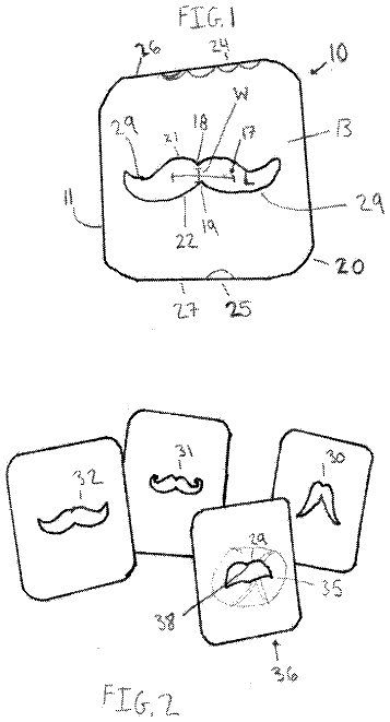
Flexible bucket-type disposable container
A flexible elastic container having a configuration matching an internal configuration of a standard bucket is provided.
US 9,963,814 B2 · Assignee: LG ELECTRONICS INC. · Inventors: Kim; Youngjun et al.
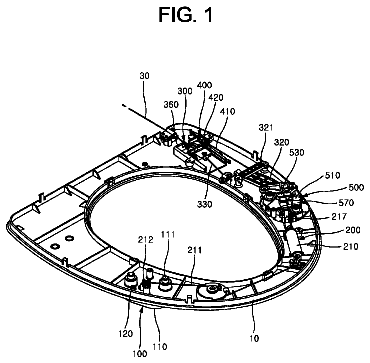
Sheet 1 of 12 from the published document. All sheets in the USPTO PDF
A washing machine including a casing, an outer tub, a support rod having one end connected to the casing and the other end having a support prop, first and second friction units movable along the support rod and applying frictional force between the friction units and the support rod, a receiving body movable along the support rod, the receiving body retaining the first and second friction units, the receiving body is integrally moved with the first friction unit and is displaceable relative to the second friction unit, an outer tub supporter movable along the support rod and formed independently of the receiving body to support the outer tub above the receiving body, and an elastic member supported by the support prop and elastically supporting the receiving body.
1.
8 of 12 drawing sheets so far from the published document, cropped to the drawing. Every sheet is in the USPTO PDF.
What the patent claimed, word for word. All of it is now free to use.
This application claims the priority benefit of Korean Patent Application Nos. 10-2014-0087718 and 10-2014-0087720 each filed on Jul. 11, 2014 in the Korean Intellectual Property Office, the disclosure of each is incorporated herein by reference.
1.
The present disclosure relates to a washing machine and, more particularly, to a washing machine which is capable of effectively attenuating vibrations.
Generally, a washing machine is an apparatus that washes laundry using, for example, emulsified detergent, water streams generated by the rotation of a wash tub or a pulsator, and shocks applied by the pulsator. The washing machine implements washing, rinsing, and/or dehydration to remove contaminants attached to the laundry (hereinafter referred to as “clothing”) using the action of detergent and water.
A conventional washing machine includes a casing defining the external appearance of the washing machine, an outer tub disposed inside the casing in a suspended form, and an inner tub rotatably provided inside the outer tub. Additionally, the washing machine further includes a suspension to prevent the outer tub from vibrating due to the rotation of the inner tub and/or the pulsator.
The suspension is typically configured to attenuate vibrations generated from the outer tub using, for example, the elasticity/restoration of springs or the viscosity of fluid. However, although this suspension may effectively attenuate vibrations in the normal vibration state, in which the outer tub vibrates within a given amplitude range, it is limited in the attenuation of vibrations in the excessive vibration state, in which the outer tub vibrates at a greater amplitude than that of the normal vibration state.
That is, in the case where the typical suspension is designed to be optimized for the excessive vibration state exhibiting a greater amplitude, the ability to attenuate normal vibrations, having a relatively small amplitude, is deteriorated. In contrast, in the case where the typical suspension is designed to be optimized for the normal vibration state, vibration attenuation sufficient to attenuate excessive vibrations cannot be expected. Therefore, there is a need to find a method for effectively attenuating vibrations both in the normal vibration state and the excessive vibration state.
In addition, although the typical suspension functions to attenuate vibrations by converting vibration into heat via friction between a support rod and a friction member moving along the support rod, this may problematically cause thermal degeneration of the friction member due to frictional heat or also cause deterioration of friction as the friction member sticks to the support rod. In particular, lubricant is applied to the support rod, in order to maintain a constant viscosity between the support rod and the friction member and to prevent overheating caused by friction. In the conventional washing machine, it is difficult to supplement the lubricant during the process of maintenance and repair.
In addition, although most constituent components of the suspension are formed by injection molding a synthetic resin, such molding becomes difficult as the structure in which the friction member is to be received becomes complicated. The constituent components of the suspension must have sufficient durability because they are operated in connection with elastic members such as springs during the vibration of the outer tub, and some portions, which need a great material thickness for durability, may be constricted during injection molding.
Therefore, the present disclosure is made to solve the problems as described above and it is a first object to provide a washing machine having a suspension which enables easy lubricant supplementation.
It is another object to provide a washing machine in which a receiving body, which receives a friction unit to generate frictional force along with a support rod, is separable from an outer tub supporter which supports an outer tub at the upper side of the receiving body.
It is still another object to provide a washing machine which exhibits different aspects of vibration attenuation in the normal vibration state, in which the amplitude of vibration of an outer tub is within a prescribed range, and in the excessive vibration state, in which the amplitude of vibration of the outer tub is relatively great.
It is yet another object to provide a washing machine which is capable of attenuating vibrations of an outer tub, thereby achieving the improved utility of space inside a casing and, especially, the increased capacity of the outer tub compared with the related art.
It is another object to provide a washing machine which is capable of achieving enhanced durability and stability and reducing the generation of noise due to vibrations.
It is another object to provide a washing machine which enables simplified supplementation of lubricant in a suspension.
It is a further object to provide a washing machine in which an injection molded component constituting a suspension is reduced in thickness, thereby restricting constriction during injection molding while achieving sufficient durability.
In accordance with one embodiment of the present invention, the above and other objects can be accomplished by the provision of a washing machine including a casing, an outer tub disposed within the casing to receive wash water therein, a support rod having one end connected to the casing, the other end of the support rod having a support prop, a first friction unit and a second friction unit movable along the support rod applying a frictional force between the first and second friction units and the support rod, a receiving body movable along the support rod, the receiving body retaining the first friction unit and the second friction unit and being integrally moved with the first friction unit and displaceable relative to the second friction unit, an outer tub supporter movable along the support rod, the outer tub supporter being formed independently of the receiving body to support the outer tub at the upper side of the receiving body, and an elastic member supported by the support prop and elastically supporting the receiving body.
The embodiments will be described in detail with reference to the following drawings in which like reference numerals refer to like elements wherein:
FIG. 1 is a side sectional view of a washing machine according to one embodiment of the present invention;
FIG. 2 is a partial perspective view illustrating a configuration in which a suspension is mounted to an outer tub illustrated in FIG. 1 ;
FIG. 3 is a partial enlarged view of portion A illustrated in FIG. 2 ;
FIG. 4 is a view illustrating a suspension according to a first embodiment of the present invention;
FIG. 5 is a view illustrating a receiving body illustrated in FIG. 4 ;
FIG. 6 is a cross sectional view illustrating a coupling portion of an outer tub supporter and the receiving body;
FIG. 7 is a view illustrating a suspension according to a second embodiment of the present invention;
FIG. 8( a ) is a view illustrating a suspension according to a third embodiment of the present invention, and FIGS. 8( b ) and 8( c ) are views respectively illustrating a friction member and a receiving body applied to the suspension;
FIG. 9 is an exploded perspective view illustrating a suspension according to a fourth embodiment of the present invention;
FIG. 10 is a front view of the suspension illustrated in FIG. 9 ;
FIG. 11 is a longitudinal sectional view of a suspension according to a fifth embodiment of the present invention; and
FIG. 12 is a view illustrating a coupling structure of a receiving body and a first friction unit of the suspension illustrated in FIG. 11 .
Advantages, features, and methods for achieving those of embodiments may become apparent upon referring to the embodiments described later in detail together with attached drawings. However, embodiments are not limited to the embodiments disclosed hereinafter, but may be embodied in different modes. The same reference numerals may refer to the same elements throughout the specification.
A washing machine according to the embodiments of the present invention that will be described below include a casing, an outer tub to receive wash water therein, a support rod having one end connected to the casing and the other end having a support prop, a first friction unit and a second friction unit configured to be movable along the support rod so as to apply frictional force between the first and second friction units and the support rod, a receiving body configured to be movable along the support rod, the receiving body retaining the first friction unit and the second friction unit and being integrally moved with the first friction unit and displaceable relative to the second friction unit, an outer tub supporter movable along the support rod, the outer tub supporter being formed independently of the receiving body to support the outer tub at the upper side of the receiving body, and an elastic member supported by the support prop and to elastically support the receiving body.
Hereinafter, the embodiments will be described in detail with reference to the drawings.
FIG. 1 is a side sectional view of a washing machine according to one embodiment of the present invention. FIG. 2 is a partial perspective view illustrating a configuration in which a suspension is mounted to an outer tub illustrated in FIG. 1 . FIG. 3 is a partial enlarged view of portion A illustrated in FIG. 2 .
Referring to FIGS. 1 to 3 , the washing machine according to one embodiment of the present invention includes a casing 1 which defines the external appearance of the washing machine, a control panel 11 which includes, for example, operating keys to receive various control instructions input by a user and a display unit to display information regarding the operating state of the washing machine, thereby constituting a user interface, and a door 7 which is rotatably coupled to casing 1 to open or close an introduction/removal hole (not illustrated) for the introduction and removal of laundry.
An outer tub 2 , in which wash water is received, is suspended inside casing 1 by a support rod 15 , and an inner tub 3 , in which laundry is received, is provided inside outer tub 2 so as to be rotatable about a vertical axis. A pulsator 4 is rotatably installed at bottom of inner tub 3 . Inner tub 3 has a plurality of holes for the passage of wash water.
Although the casing defined in the present invention is sufficient so long as it forms the external appearance of the washing machine, in particular, the casing may be a stationary body which is immovable so that one end of support rod 15 , which suspends outer tub 2 inside the casing, may be fixed by the casing. Casing 1 as described below is merely one example of a structure forming the external appearance of the washing machine and it is specified that the range of the casing described in the claims of the present application should not be limited thereto.
Casing 1 includes a cabinet 12 having an open upper side and a top cover 14 provided at the upper side of cabinet 12 , top cover 14 being formed at an approximately central portion thereof with an introduction/removal hole for the introduction and removal of laundry.
Support rod 15 extends by a long length in the longitudinal direction thereof and has one end connected to casing 1 and the other end connected to outer tub 2 via a suspension 100 . One end of support rod 15 may be connected to any one of cabinet 12 and top cover 14 , and cabinet 12 or top cover 14 may include a connector (not illustrated) which is pivotally connected to support rod 15 .
Support rod 15 may include a support prop 160 provided at the other end thereof. Support prop 160 serves to support an elastic member 150 fitted around support rod 15 so as not to be separated from support rod 15 . Support prop 160 has a support surface to support a lower end of elastic member 150 so as to prevent elastic member 150 from being separated from support rod 15 , and the support surface may have a greater area than the cross section of elastic member 150 .
Rotation of elastic member 150 about support rod 15 may be restricted by support prop 160 . In some embodiments, support prop 160 may be formed with a coupling portion to be coupled to the lower end of elastic member 150 , or may be formed with a raised portion to limit the rotation of the lower end of elastic member 150 .
A water supply flow path 5 is connected to an external water source such as, for example, a water tap to supply water into outer tub 2 and/or inner tub 3 . A water supply valve 6 is provided to control water supply flow path 5 . A drive unit 13 serves to drive inner tub 3 and/or pulsator 4 . A drain flow path 9 is connected to outer tub 2 to discharge wash water from outer tub 2 . A drain valve 8 is provided to control drain flow path 9 . A drain pump 10 is installed to drain flow path 9 to pump the discharged wash water to the outside of the washing machine.
Suspension 100 serves to attenuate vibrations of outer tub 2 attributable to the rotation of inner tub 3 or pulsator 4 . Suspension 100 is coupled to a lower end of outer tub 2 . This coupling may be separable coupling to ensure easy installation and separation of suspension 100 . For example, FIG. 3 illustrates a mount 2 a which protrudes from the outer circumferential surface of a lower portion of outer tub 2 for the installation of suspension 100 , and mount 2 a may be formed with a slit 2 b which extends in the vertical direction and is open in the lateral direction.
To couple suspension 100 and outer tub 2 to each other, once suspension 100 has been installed to support rod 15 , support rod 15 is inserted into mount 2 a through a lateral opening of slit 2 b and mount 2 a is seated on an outer tub supporter 110 that will be described below. Since the weight of outer tub 2 is continuously applied to outer tub supporter 110 , outer tub 2 and outer tub supporter 110 are integrally moved without separation. Meanwhile, separation of suspension 100 for maintenance and repair is easily implemented by pulling suspension 100 slightly downward and removing support rod 15 through the lateral opening of slit 2 b.
In the following description of the embodiments of the suspension with reference to the drawings, common components of the washing machine to which the suspension is applied will refer to FIGS. 1 to 3 .
FIG. 4 is a view illustrating a suspension according to a first embodiment of the present invention. FIG. 5 is a view illustrating a receiving body illustrated in FIG. 4 . FIG. 6 is a cross sectional view illustrating a coupling portion of an outer tub supporter and the receiving body.
Referring to FIGS. 4 to 6 , suspension 100 includes outer tub supporter 110 , a receiving body 120 , elastic member 150 , a first friction unit 130 , and a second friction unit 140 .
Outer tub supporter 110 is configured to support outer tub 2 and is movable along support rod 15 . Outer tub supporter 110 may include a tubular slider 111 for the penetration of support rod 15 and a seating portion 112 expanding outward from slider 111 to form a seating surface 112 a on which outer tub 2 is seated. Seating portion 112 may be caught by mount 2 a of outer tub 2 and an upper end of slider 111 may protrude upward from mount 2 a.
Receiving body 120 is movable along support rod 15 and elastically supported by elastic member 150 . A lower end of elastic member 150 is supported by support prop 160 and an upper end of elastic member 150 supports receiving body 120 .
Outer tub supporter 110 supports outer tub 2 at the upper side of receiving body 120 . Outer tub supporter 110 may be formed as a unit separated from receiving body 120 . This configuration ensures easy injection of lubricant. It is necessary to inject or supplement lubricant during the process of manufacturing the washing machine as well as when performing maintenance and repair during the useful lifetime thereof. At this time, outer tub supporter 110 , separated from receiving body 120 , is pushed upward to expose support rod 15 covered with outer tub supporter 110 , and the lubricant may be directly applied to the exposed portion. In addition, the lubricant may also be injected to first friction unit 130 or second friction unit 140 , which are arranged inside receiving body 120 . This lubricant injection is very convenient because it can be performed even without separating suspension 100 from support rod 15 .
Meanwhile, even if outer tub supporter 110 and receiving body 120 are not firmly coupled to each other, outer tub supporter 110 and receiving body 120 may be integrated with each other, i.e. they may be moved together along support rod 15 by the weight of outer tub 2 applied to outer tub supporter 110 and the restoration of elastic member 150 that supports receiving body 120 because outer tub supporter 110 supports outer tub 2 at the upper side of receiving body 120 .
First friction unit 130 and second friction unit 140 are movable along support rod 15 respectively such that frictional force (more particularly, kinetic friction during the vibration of outer tub 2 ) is generated between the respective friction units and support rod 15 . First friction unit 130 and second friction unit 140 are received in receiving body 120 . First friction unit 130 and second friction unit 140 may respectively include friction members to generate frictional force between the respective friction units 130 and 140 and the outer circumferential surface of support rod 15 .
Receiving body 120 may retain first friction unit 130 and second friction unit 140 . When being moved along support rod 15 , receiving body 120 may be moved integrally with first friction unit 130 , but may be displaceable relative to second friction unit 140 .
The friction members constituting first friction unit 130 and/or second friction unit 140 may be formed of a porous fiber material such as, for example, felt, or may be formed of an elastic material such as, for example, rubber. In addition, in terms of the shape, the friction members may have a tubular shape so as to be fitted around support rod 15 , or may take the form of a flexible sheet or band so as to be wound around the outer circumferential surface of support rod 15 . In particular, the fibrous friction member has excellent absorbency for a lubricant. Hereinafter, the friction member included in first friction unit 130 is referred to as a first friction member and the friction member included in second friction unit 140 is referred to as a second friction member.
In some embodiments, each of first friction unit 130 and second friction unit 140 may include a receptacle (for example, a second friction member housing 142 ) to receive the friction member therein. The receptacle is configured to firmly support the friction member and to maintain the outer appearance of the friction unit and is adapted to slide along the inner circumferential surface of receiving body 120 , thereby stably supporting the movement of friction units 130 and 140 . However, since first friction unit 130 is fixed to receiving body 120 and is sufficiently supported by a first receiving portion 121 of receiving body 120 , hereinafter, the case where first friction unit 130 is the friction member itself will be described by way of example.
Friction between the two friction units 130 and 140 and support rod 15 exhibits different aspects based on the amplitude of vibration of outer tub 2 . For example, when operating the washing machine, in the case where outer tub 2 resonates based on the physical properties of the entire vibration system, or for an excessive vibration period, during which excessive vibrations are generated due to the unbalanced arrangement of clothing inside inner tub 3 , first friction unit 130 and second friction unit 140 are moved integrally with outer tub supporter 110 (or receiving body 120 ), causing kinetic friction between friction units 130 and 140 and support rod 15 . Accordingly, for the excessive vibration period, vibration energy is positively dissipated by friction of both first and second friction units 130 and 140 .
On the other hand, for a period, during which the amplitude of vibration of outer tub 2 is sufficiently lower than that of the excessive vibration period (e.g., a normal vibration period), only first friction unit 130 performs vibration attenuation by friction. That is, second friction unit 140 may remain stationary at a prescribed position on support rod 15 while being separated from receiving body 120 when first friction unit 130 is moved along support rod 15 . Outer tub 2 can vibrate relatively freely while vibration attenuation by friction is implemented only by first friction unit 130 .
That is, when operating the washing machine, suspension 100 implements vibration attenuation using one friction unit 130 during the relatively stable period, but implements positive attenuation by friction using the two friction units 130 and 140 during the excessive vibration period. That is, the washing machine according to the present embodiment allows outer tub 2 to be moved relatively freely within a predetermined allowable amplitude range in consideration of, for example, the durability of the appliance and an allowable vibration displacement, but more positively attenuates vibrations to limit the amplitude of vibration when vibrations are generated beyond a given level. As such, the washing machine shows different aspects of vibration attenuation based on the amplitude of vibration.
To allow vibration attenuation by first friction unit 130 and second friction unit 140 to be implemented in different aspects depending on the amplitude of vibration of outer tub 2 , first, the maximum displacement of second friction unit 140 must be greater than the maximum displacement of first friction unit 130 which is permitted due to their relationships with respect to receiving body 120 . Preferably, first friction unit 130 is fixed to receiving body 120 and second friction unit 140 is permitted to be displaced relative to receiving body 120 within the space delimited by receiving body 120 .
In this sense, receiving body 120 includes first receiving portion 121 in which first friction unit 130 is received, and a second receiving portion 126 in which second friction unit 140 is received. First friction unit 130 is fixed to receiving body 120 inside first receiving portion 121 . Second receiving portion 126 provides a space for reception of second friction unit 140 , which is longer than the longitudinal length of second friction unit 140 , so as to permit relative movement between receiving body 120 and second friction unit 140 .
Second receiving portion 126 may be located below first receiving portion 121 , and receiving body 120 may include a partition 121 c to separate first receiving portion 121 and second receiving portion 126 from each other. Support rod 15 passes through the central portion of partition 121 c . On the basis of partition 121 c , first receiving portion 121 is defined as an upper portion of receiving body 120 and second receiving portion 126 is defined as a lower portion of receiving body 120 .
First receiving portion 121 may include a tubular upper side portion 121 b , through the center of which support rod 15 passes. Upper side portion 121 b extends upward from partition 121 c . Lubricant may be received in the space delimited by upper side portion 121 b and partition 121 c . First friction member 130 may be submerged in the lubricant depending on the materials thereof, and some of the lubricant may permeate through a gap between first friction member 130 and partition 121 c to reach support rod 15 .
Meanwhile, first receiving portion 121 may include a plurality of ribs 121 d which extend from the inner circumferential surface of upper side portion 121 b toward the center at which support rod 15 is located. Ribs 121 d have outer ends connected to the inner circumferential surface of upper side portion 121 b and lower ends connected to upper surface of partition 121 c . First friction member 130 is interposed between inner ends of ribs 121 d and support rod 15 . First friction member 130 is disposed in a space 127 which is delimited by the inner ends of ribs 121 d . First friction member 130 , which has been compressed to a given level, may be fitted into space 127 such that the outer circumferential surface of first friction member 130 continuously remains in contact with the inner ends of ribs 121 d . In addition, the inner ends of ribs 121 d may radially extend to converge toward the center of upper side portion 121 b . Ribs 121 d may be symmetrically arranged about the center.
Since the space is formed around the periphery of first friction member 130 and the lubricant or air is received in the space, heat generated by the friction between first friction member 130 and support rod 15 may be easily dissipated. This may prevent first friction member 130 from being degenerated by high temperature heat, or may prevent first friction member 130 from sticking to support rod 15 .
Meanwhile, to achieve more positive heat dissipation, as exemplarily illustrated in FIG. 5 , first receiving portion 121 may be configured such that the space in which first friction member 130 is received is open.
Second receiving portion 126 may include lower side portions 123 a and 123 b which extend downward from first receiving portion 121 to form a space for the reception of second friction unit 140 . Although the lower side portions may be configured as a tubular portion extending throughout the periphery of upper side portion 121 b , as exemplarily illustrated in FIG. 5 , second friction unit 140 may have openings 126 h which are open in the transverse direction for ventilation of the space for the reception of second friction unit 140 . This has the effect of radiating frictional heat generated by second friction unit 140 through openings 126 h.
More specifically, second receiving portion 126 may include a bottom portion 124 which delimits a lower end of the space for the reception of second friction unit 140 and lower side portions 123 a and 123 b which connect bottom portion 124 and first receiving portion 121 to each other. Although a first lower side portion 123 a and a second lower side portion 123 b are provided with openings 126 h interposed therebetween in the present embodiment, the present invention should not be limited thereto and an opening may be formed in the lower side portion.
Second friction unit 140 is moved by being pushed by receiving body 120 when the amplitude of vibration of outer tub 2 reaches a given level or higher. In the embodiment, second friction unit 140 is moved downward by being pushed by partition 121 c and is moved upward by being pushed by bottom portion 124 .
Second friction unit 140 may further include friction member housing 142 in which second friction members 141 are received at upper and lower positions. Friction member housing 142 may include a tubular housing side portion 142 a and a division plate 142 b which divides a space inside housing side portion 142 a into upper and lower spaces, support rod 15 penetrating division plate 142 b . Friction member housing 142 may receive second receiving members 141 respectively in the upper and lower spaces divided by division plate 142 b.
Partition 121 c may include at least one protrusion 128 a which protrudes downward from the lower surface thereof. Protrusion 128 a may be formed around an aperture, through which support rod 15 passes. When receiving body 120 is moved downward, protrusion 128 a comes into contact with an upper end of second friction unit 140 . Protrusion 128 a may be located to come into contact with second friction member 141 .
Bottom portion 124 may include at least one protrusion 128 b which protrudes upward from the upper surface thereof. Protrusion 128 b may be formed around an aperture, through which support rod 15 passes. When receiving body 120 is moved upward, protrusion 128 b comes into contact with a lower end of second friction unit 140 . Protrusion 128 b may be located to come into contact with second friction member 141 .
This configuration in which protrusions 128 a and 128 b are formed at partition 121 c or bottom portion 124 has the effect of reducing the collision area between receiving body 120 and second friction members 141 , thereby reducing collision noise.
Meanwhile, receiving body 120 is supported by elastic member 150 . Receiving body 120 may include an outer circumferential protruding portion 121 a which protrudes further outward than does lower side portions 123 a and 123 b so as to be supported at a lower end thereof by an upper end of elastic member 150 . In the present embodiment, outer circumferential protruding portion 121 a extends from first receiving portion 121 to the outside of lower side portions 123 a and 123 b.
Only a small clearance may be present between outer tub supporter 110 and receiving body 120 during the vibration of outer tub 2 . For example, in the case where outer tub 2 is moved upward a considerably great height during the vibration thereof or in the case where the speed of upward movement of outer tub 2 is greater than the restoration speed of elastic member 150 , outer tub supporter 110 and receiving body 120 may be very close to each other. Outer tub supporter 110 and receiving body 120 , separated from each other as described above, may cause collision noise when outer tub 2 is moved downward and may have a bad effect on durability. To solve this problem, suspension 100 may further include a damping member 180 interposed between outer tub supporter 110 and receiving body 120 . Damping member 180 may be formed of a porous fiber material or an elastic material such as, for example, rubber.
Damping member 180 may have openings 181 which communicate with the interior of first receiving portion 121 . In this case, heat generated by first friction member 130 is radiated through openings 181 . Openings 181 may be located to correspond to gaps between neighboring ribs 121 d.
FIG. 7 is a view illustrating a suspension according to a second embodiment of the present invention. FIG. 8 illustrates the partially disassembled state of the suspension illustrated in FIG. 7 . More particularly, FIG. 8 illustrates a first receiving portion 221 without first friction member 130 .
Referring to FIGS. 7 and 8 , suspension 200 may include an outer tub supporter 210 , a receiving body 220 and 270 , first friction unit ( 130 , see FIG. 6 ), second friction unit 140 , and elastic member ( 150 , see FIG. 3 ). Outer tub supporter 210 has substantially the same configuration as outer tub supporter 110 according to the previously described embodiment and a detailed description thereof follows the above description and thus will be omitted below.
Receiving body 220 and 270 may retain first friction unit 130 and second friction unit 140 and may be integrally moved with first friction unit 130 , but may be displaceable relative to second friction unit 140 when being moved along support rod 15 .
More specifically, the receiving body includes a first receiving portion forming part 220 which forms first receiving portion 221 and a second receiving portion forming part 270 which forms a space for the reception of second friction unit 140 along with first receiving portion forming part 220 inserted thereinto. That is, in the present embodiment, a second receiving portion 226 for the reception of second friction unit 140 is constituted of first receiving portion forming part 220 and second receiving portion forming part 270 . A partition 224 is formed at first receiving portion forming part 220 , and first receiving portion 221 , which corresponds to a portion above partition 224 , is substantially identical to first receiving portion 121 of the previously described embodiment.
An upward indentation 223 is formed in the lower surface of first receiving portion forming part 220 , and second friction unit 140 may be inserted upward into indentation 223 during vibration. Of course, indentation 223 may not be formed in first receiving portion forming part 220 , and the space for the reception of second friction unit 140 may be formed only in second receiving portion forming part 270 .
Second receiving portion forming part 270 includes an upper side portion 271 which protrudes further outward than does a lower side portion 273 . A stepped portion 272 , which corresponds to the difference between the outer diameters of upper side portion 271 and lower side portion 273 , is supported by elastic member 150 . In addition, partition 224 is formed at first receiving portion forming part 220 such that first friction member 130 is seated on partition 224 . A protrusion 228 may protrude downward from the lower surface of partition 224 toward the space for the reception of second friction unit 140 . In addition, a protrusion 278 may be formed at a bottom portion 274 of second receiving portion forming part 270 so as to protrude upward toward the space for the reception of second friction unit 140 . These protrusions 228 and 278 may come into contact with second friction members 141 in the same manner as protrusions 128 a and 128 b of the previously described embodiment.
Meanwhile, in the same manner as the previously described embodiment, first receiving portion 221 may be formed with a plurality of radial ribs 121 d having inner ends which converge toward the center, through which support rod 15 passes. First receiving portion 121 has substantially the same configuration as first receiving portion 121 of the previously described embodiment, but has a difference in that it is included in first receiving portion forming part 220 independently of second receiving portion forming part 270 in the present embodiment.
FIG. 8( a ) is a view illustrating a suspension according to a third embodiment of the present invention, and FIGS. 8( b ) and 8( c ) are views respectively illustrating a friction member and a receiving body applied to the suspension. Referring to FIG. 8 , suspension 300 according to the third embodiment of the present invention has a configuration similar to that of suspension 100 according to the previously described embodiment and includes an outer tub supporter 310 , a receiving body 320 , elastic member 150 , first friction unit 130 (see, FIG. 6 ), and a second friction unit 340 . The first and second friction unit 130 , 340 may have friction member 341 , respectively.
Receiving body 320 may retain first friction unit 130 and second friction unit 340 . When being moved along support rod 15 , receiving body 320 may be moved integrally with the first friction unit or the first friction member 130 , but may be displaceable relative to second friction unit 340 .
More specifically, receiving body 320 may include a first receiving portion 321 and a second receiving portion 326 . Although not illustrated in FIG. 8 , first friction member ( 130 ) is received in first receiving portion 321 .
First receiving portion 321 may include a plurality of first ribs 321 b which extend from an inner circumferential surface 321 a , delimiting the space for the reception of first friction member 130 , toward the center at which support rod 15 is located, and a plurality of second ribs 321 d which protrude from the upper surface of a partition 321 c , configured to separate first receiving portion 321 and second receiving portion 326 from each other, i.e. from the bottom surface of first receiving portion 321 so as to support first friction member 130 . First ribs 321 b come into contact with the outer circumferential surface of first friction member 130 , and second ribs 321 d come into contact with a lower end of first friction member 130 .
Second ribs 321 d may extend toward the center by a longer length than first ribs 321 b . An annular rib 321 e may protrude along the periphery of an aperture formed in partition 321 c for the passage of support rod 15 . In this case, second ribs 321 d may extend to annular rib 321 e.
A prescribed gap is formed between the bottom surface of first receiving portion 321 and first friction member 130 by second ribs 321 d . Thus, lubricant injected into first receiving portion 321 may move downward through spaces between first ribs 321 d to thereby gather between second ribs 321 d . First friction member 130 may be formed of a porous fiber material for excellent absorbency.
Second friction unit 340 may include a cylindrical friction member 341 , into which support rod 15 is inserted, and a tubular friction member housing 342 in which friction member 341 is received. Upper and lower ends of friction member 341 protrude outward from friction member housing 342 so as to respectively come into contact with protrusion 128 a formed at the lower surface of partition 321 c and protrusion 128 b protruding upward from bottom portion 324 of second receiving portion 326 during movement thereof.
The washing machine as described above has the effect of enabling simple supplementation of the lubricant in the suspension. In particular, the lubricant may be directly injected to the friction unit, which applies frictional force between the friction unit and the support rod.
In addition, the receiving body, in which the friction unit, which applies frictional force between the friction unit and the support rod, is received, is separable from the outer tub supporter which supports the outer tub at the upper side of the receiving body, which enables the lubricant to be directly injected to the receiving body in the state in which the outer tub supporter is lifted, resulting in simplified supplementation and maintenance of the lubricant.
In addition, the washing machine may effectively attenuate vibrations not only in the normal vibration state, in which the amplitude of vibration of the outer tub is within a prescribed range, but also in the excessive vibration state, in which the amplitude of vibration of the outer tub deviates from the prescribed range.
Additionally, by attenuating vibrations of the outer tub, the washing machine has the effect of improving the utility of space inside the casing and, especially, increasing the capacity of the outer tub compared with the related art.
The washing machine has the effect of achieving enhanced durability and stability and reducing the generation of noise due to vibrations.
FIG. 9 is an exploded perspective view illustrating a suspension according to a fourth embodiment of the present invention. FIG. 10 is a front view of the suspension illustrated in FIG. 9 .
Referring to FIGS. 9 and 10 , suspension 400 according to the fourth embodiment of the present invention includes an outer tub supporter 410 , a receiving body 420 , elastic member ( 150 , see FIG. 3 ), a first friction unit 440 , and a second friction unit 470 .
Outer tub supporter 410 is configured to support outer tub 2 and is movable along support rod 15 . Outer tub supporter 410 may include a tubular slider 411 for the penetration of support rod 15 and a seating portion 412 expanding outward from slider 411 to form a seating surface 412 a on which outer tub 2 is seated. Seating portion 412 may be caught by mount 2 a of outer tub 2 and at least a portion of slider 411 may protrude upward from mount 2 a . A lubricant such as, for example, grease may be applied to a portion of slider 411 coming into contact with support rod 15 (i.e., the inner circumferential surface of an inner elongated bore).
The description continues in the full USPTO document.
About 6,842 words. The USPTO PDF has it with every drawing.
Fees are due 3.5, 7.5 and 11.5 years after grant. This patent expired on May 8, 2026, so the fee marked "not paid" was the one that went unpaid.
WASHING MACHINE
Filed Jul 2015 · published Jan 2016Washing machine
Filed Jul 2015 · granted May 2018Earlier publications, parents and continuations. None of them can still be enforced, or this patent would not be listed.
Prior art cited by the examiner or applicant. Useful when you check your own idea for novelty.
Everything on this page comes from the documents linked above.