 Lapsed, fee not paid1 drawing
Medical Devices · US 9,962,256 B2
Buttressed haptic
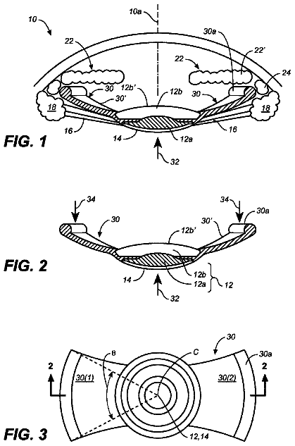
A haptic supporting an intraocular lens (IOL) in the eye permits radial tension from ciliary muscle relaxation rather than contraction to alter the lens power.
US 9,962,259 B2 · Assignee: National University of Singapore · Inventors: Leo; Hwa Liang et al.
Sheet 1 of 27 from the published document. All sheets in the USPTO PDF
In various embodiments, a stent member is provided. The stent member may include a self-expanding stent frame defining in its expanded position a central annular opening along a longitudinal axis, the opening extending from a first end to a second end of the stent frame. The stent member may include at least one anchoring structure extending radially outwards from the second end of the stent frame. The stent member may further include a biocompatible coating on the stent frame.
Mitral regurgitation (MR) makes up 35% of the observed cases of native valve diseases. The treatment for mitral regurgitation is controversial and depends on the extent of the diseased tissue and the expertise of the surgeon. Even though mitral valve repair is preferable to replacement in many patients because it brings better heart functions with less risk of infection, blood clots and stroke, the surgical procedure may take longer, has steeper learning curve and often requires extensive surgical skill on the part of the surgeon. As a result, only high volume heart centers have the necessary skills to routinely perform mitral valve repairs. Heart valve replacement remains a ‘gold standard’ in the treatment of many heart valve diseases but suffers from the risks of open chest surgery complications such as infections and blood clot, which could severely compromise the recovery and surviva
1 of 27 drawing sheets so far from the published document, cropped to the drawing. Every sheet is in the USPTO PDF.
What the patent claimed, word for word. All of it is now free to use.
This application claims the benefit of priority of SG application No. 201304925-9 filed Jun. 25, 2013, the contents of it being hereby incorporated by reference in its entirety for all purposes.
Various aspects of this disclosure relate to stent members, artificial valves and methods of implanting the same.
Mitral regurgitation (MR) makes up 35% of the observed cases of native valve diseases. The treatment for mitral regurgitation is controversial and depends on the extent of the diseased tissue and the expertise of the surgeon. Even though mitral valve repair is preferable to replacement in many patients because it brings better heart functions with less risk of infection, blood clots and stroke, the surgical procedure may take longer, has steeper learning curve and often requires extensive surgical skill on the part of the surgeon. As a result, only high volume heart centers have the necessary skills to routinely perform mitral valve repairs. Heart valve replacement remains a ‘gold standard’ in the treatment of many heart valve diseases but suffers from the risks of open chest surgery complications such as infections and blood clot, which could severely compromise the recovery and survival rates of patients.
In summary, for most patients suffering from valvular heart diseases such as mitral regurgitation (MR) and and other heart diseases such as stenosis, heart valve replacement remains the only option for the alleviation of symptoms. However, the surgical approach is associated with substantial operative mortality rates in high risk patients. As a result, a less invasive and a safer approach to heart valve replacements may be required.
In various embodiments, a stent member is provided. The stent member may include a self-expanding stent frame defining in its expanded position a central annular opening along a longitudinal axis, the opening extending from a first end to a second end of the stent frame. The stent member may include at least one anchoring structure extending radially outwards from the second end of the stent frame. The stent member may further include a biocompatible coating on the stent frame.
The invention will be better understood with reference to the detailed description when considered in conjunction with the non-limiting examples and the accompanying drawings, in which:
FIG. 1 shows a schematic of a stent member according to various embodiments.
FIG. 2A shows a perspective view of a stent member according to various embodiments; FIG. 2B shows a side view of a stent member similar to the stent member illustrated in FIG. 2A according to various embodiments; FIG. 2C shows a top view of a stent member similar to the stent member illustrated in FIG. 2A according to various embodiments; FIG. 2D shows a perspective view of a stent member similar to the stent member illustrated in FIG. 2A in a collapsed state according to various embodiments; and FIG. 2E shows a side view of a stent member similar to the stent member illustrated in FIG. 2A according to various embodiments being deployed as part of a percutaneous mitral valve replacement device in the heart.
FIG. 3A shows a perspective view of a stent member according to various embodiments; FIG. 3B shows a side view of a stent member similar to the stent member illustrated in FIG. 3A according to various embodiments; FIG. 3C shows a top view of a stent member similar to the stent member illustrated in FIG. 3A according to various embodiments; FIG. 3D shows a perspective view of a stent member similar to the stent member illustrated in FIG. 3A in a collapsed state according to various embodiments; and FIG. 3E shows a side view of a stent member similar to the stent member illustrated in FIG. 3A according to various embodiments being deployed as part of a percutaneous mitral valve replacement device in the heart.
FIG. 4A shows a perspective view of a stent member according to various embodiments; FIG. 4B shows a side view of a stent member similar to the stent member illustrated in FIG. 4A according to various embodiments; FIG. 4C shows a top view of a stent member similar to the stent member illustrated in FIG. 4A according to various embodiments; FIG. 4D shows a perspective view of a stent member similar to the stent member illustrated in FIG. 4A in a collapsed state according to various embodiments; and FIG. 4E shows a side view of a stent member similar to the stent member illustrated in FIG. 4A according to various embodiments being deployed as part of a percutaneous mitral valve replacement device in the heart.
FIG. 5A shows a perspective view of a stent member according to various embodiments; FIG. 5B shows a side view of a stent member similar to the stent member illustrated in FIG. 5A according to various embodiments; FIG. 5C shows a top view of a stent member similar to the stent member illustrated in FIG. 5A according to various embodiments; FIG. 5D shows a perspective view of a stent member similar to the stent member illustrated in FIG. 5A in a collapsed state according to various embodiments; and FIG. 5E shows a side view of a stent member similar to the stent member illustrated in FIG. 5A according to various embodiments being deployed as part of a percutaneous mitral valve replacement device in the heart.
FIG. 6 shows a perspective view of a stent member according to various embodiments.
FIG. 7 shows a perspective view of a stent member according to various embodiments.
FIG. 8A shows a perspective view of a stent member according to various embodiments; FIG. 8B shows a side view of a stent member similar to the stent member illustrated in FIG. 8A according to various embodiments; FIG. 8C shows a top view of a stent member similar to the stent member illustrated in FIG. 8A according to various embodiments; FIG. 8D shows a perspective view of a stent member similar to the stent member illustrated in FIG. 8A in a collapsed state according to various embodiments; and FIG. 8E shows a side view of a stent member similar to the stent member illustrated in FIG. 8A according to various embodiments being deployed as part of a percutaneous mitral valve replacement device in the heart.
FIG. 9 shows a perspective view of a stent member according to various embodiments.
FIG. 10 shows a perspective view of a stent member according to various embodiments.
FIG. 11 shows a perspective view of a stent member according to various embodiments.
FIG. 12 shows a perspective view of a stent member according to various embodiments.
FIG. 13 shows a perspective view of a stent member according to various embodiments.
FIG. 14A shows a perspective view of a stent member according to various embodiments; FIG. 14B shows a side view of a stent member similar to the stent member illustrated in FIG. 14A according to various embodiments; FIG. 14C shows a top view of a stent member similar to the stent member illustrated in FIG. 14A according to various embodiments; FIG. 14D shows a perspective view of a stent member similar to the stent member illustrated in FIG. 14A in a collapsed state according to various embodiments; and FIG. 14E shows a side view of a stent member similar to the stent member illustrated in FIG. 14A according to various embodiments being deployed as part of a percutaneous mitral valve replacement device in the heart.
FIG. 15 is a schematic illustrating a method of implanting an artificial valve.
The following detailed description refers to the accompanying drawings that show, by way of illustration, specific details and embodiments in which the invention may be practiced. These embodiments are described in sufficient detail to enable those skilled in the art to practice the invention. Other embodiments may be utilized and structural, and logical changes may be made without departing from the scope of the invention. The various embodiments are not necessarily mutually exclusive, as some embodiments can be combined with one or more other embodiments to form new embodiments.
In order that the invention may be readily understood and put into practical effect, particular embodiments will now be described by way of examples and not limitations, and with reference to the figures.
Features have been labeled wherever appropriate. However, for the sake of clarity and in order to avoid clutter, not all features in some of the figures have been labeled.
It should be understood that the terms “top”, “bottom”, “upper”, “lower”, “side” etc., when used in the following description are used for convenience and to aid understanding of relative positions or directions, and not intended to limit the orientation of the stent member or artificial valve, either before or after deployment.
Minimally-invasive replacement of diseased heart valve is an attractive option in addressing the risks of open heart surgery. Percutaneous valve replacement constitutes one of the latest directions in heart valve engineering in which the prosthetic heart valve is delivered and deployed in place of the diseased valve through a delivery device such as a catheter. Currently, there are basically two approaches to the implantation of the valve; 1) transfemorally, via an incision in the femoral vein and transseptally to the valve (as in the mitral valve replacement), and 2) transapical, i.e. via a small incision between the ribs and up through the apex of the heart. This surgical procedure may typically take 1-2 hours (sometime even less) and recovery may be measured in days, not months as in the case of a traditional surgical procedure.
Transcatheter aortic valves currently dominate the research and media communities. Both Edward Life Sciences (Edwards Sapien) and Medtronic, Inc (CoreValve) have established transcatheter programs and have aortic valves already in clinical trials. Edwards Sapien's transcatheter aortic valve has received approval from the United States Food Drug Administration (FDA). The next-generation transcatheter aortic valves currently in clinical trials are Direct Flow Medical, Inc Direct Flow valve, and Sadra Medical, Inc Lotus valve (both are for aortic replacement). Several companies in recent years have also developed their own transcatheter aortic valve programs. These include Heart Leaflet Technologies, Advanced Bioprosthetic Surfaces, Hansen Medical (HNSN) AorTx, JenaValve Technology and the Symetis. None of these aortic valve prostheses are currently in clinical trials. Due to the anatomical and location differences in the aortic and mitral valves, the technical requirements for transcatheter aortic valve may be less demanding than that of the mitral valve. The latter position in the heart may be constrained by relatively restrictive mitral annulus which imposes a strain on the anchoring mechanism design. In contrast, the aortic valve is connected to the aortic arch, which could potentially provide ample space for anchoring of the valve. Indeed, most current transcatheter aortic valve designs (such as CoreValve) may make use of an extended distal frame segment for anchorage.
The advance of transcatheter mitral valve research is generally not as well established as its aortic counterpart. Several conceptual percutaneous mitral valve designs have been proposed and patented, however at present, the documentation on percutaneous replacement of diseased mitral heart valve experiments is still limited. Ma et al. (Eur J Cardiothorac Surg 28(2): 194-8; discussion 198-9) reported in 2005 the first percutaneous mitral valve replacement experiment performed on eight pigs. The percutaneous mitral valve has a shape that resembles a double opposite crown. Two glutaraldehyde preserved aortic and six glutaraldehyde-preserved pulmonary valvular homografts are sutured to the 20 mm diameter Dacron tube, which is attached to the middle stent of the eight valves. The valve prostheses are introduced into the left atrium and deployed at the mitral position. No significant hemodynamic episode was reported 30 mins after stent deployment. The total deployment time took 15-20 s. One animal died of occlusion of the Left Ventricular Outflow Obstruction (LVOT) attributed to the dislodgement of the implant as a result of valve-annulus size mismatch 40 mins after the implantation. The remaining seven survived beyond the 40 mins (survival range 40-180 mins). The study demonstrated the feasibility of the transluminal deployment of mitral valve. Lozonschi et al. (Ann Thorac Surg 86(3): 745-8) reported in 2008 the implantation of the similar mitral valve prototype on 10 pigs through trans-apical insertion. All pigs survived the 60 mins postdeployment with no report of abnormal hemodynamic episode. A year before in 2007, Endovalve, Inc presented their first prototype with small preclinical trial with sheep, however there has not been a follow-up since. The Endovalve percutaneous mitral valve, after deployment, has a gripping mechanism that holds the valve prosthesis in place, and a three-point supporting stmt, which lies across the flow orifice upstream of the leaflets to help maintain the annulus geometry of the valve. However, the strut may hinder the orifice flow and compromise the hemodynamic performance of the valve. Even though early experiences with these valve types, are limited, the initial success with the deployment of these valve prostheses are encouraging, highlighting the fact that transcatheter approach to heart valve replacement is increasingly recognized as a more effective alternative to the more invasive surgical valve replacement. Percutaneous mitral valve prostheses may offer the potential to circumvent many of the problems currently faced by open chest surgery.
FIG. 1 shows a schematic 100 of a stent member according to various embodiments. The stent member may include a self-expanding stent frame 102 defining in its expanded position a central annular opening 104 along a longitudinal axis 106 . The annular opening may extend from a first end 108 a to a second end 108 b of the stent frame 102 . The stent member may include at least one anchoring structure 110 extending radially outwards from the second end of the stent frame 102 . The stent member may further include a biocompatible coating 112 on the stent frame 102 .
In other words, a stent member including a stent frame 102 and at least least one anchoring structure 110 extending from the stent frame 102 may be provided. The anchoring structure 110 may protrude outwards from the stent frame 102 . The stent frame 102 may expand by itself in the absence of a restraining force. The stent frame 102 may be tubular (in an expanded state) and may include an opening 104 extending axially, i.e. along axis 106 , from a first end 108 a of the stent frame 102 to a second end 108 b of the stent frame 102 . The stent member may further include a biocompatible coating 112 on the stent frame 102 .
Various embodiments may hold the promise for less surgical-associated complications, with improved patient's survival rate and shorter recovery time. Various embodiments may present a transcatheter approach to the replacement of diseased heart valves, especially mitral heart valves.
In various embodiments, the stent frame 102 may also be referred to as a band mid section or mid section of the valve prosthesis. The stent frame 102 may be a tubular structure. A valve member such as a porcine or bovine pericardial heart valve may be attached or sutured to the stent frame 102 . The anchoring structure 110 may also be referred to as a lower supporting frame. The anchoring structure 110 may also be self-expanding.
The anchoring structure 110 may be configured to expand and anchor on biological tissue such as the inflow or outflow annulus of a mitral valve upon release of the stent member from a catheter.
In various embodiments, the artificial valve (including the stent member and the valve member attached or sutured to the stent frame 102 ) may be referred to as a percutaneous mitral valve or a percutaneous mitral valve replacement device and be configured to replace at least some functions of a biological human mitral valve. The artificial valve may be configured to be deployed between the left atrium and the left ventricle. The artificial valve may be configured to help restore normal physiological flow of blood from the left atrium to the left ventricle. The stent frame 102 may be configured so that the artificial valve may be re-positionable and retrieveable before final deployment, i.e. before the artificial valve is anchored. The percutaneous mitral valve may have a geometry that conform to the three dimensional saddle shape of the human mitral annulus, and may have an elliptical flow orifice akin to the human mitral valve. In other words, the stent frame 102 may be configured so that when a valve member is attached or sutured to the stent frame 102 , the resulting artificial valve has a structure that is similar to the human mitral valve, such as having a three dimensional saddle shape and/or elliptical flow orifice.
In various alternate embodiments, the artificial valve may be configured to be deployed between the right atrium and the right ventricle and be configured to replace at least some functions of the tricuspid valve. In various other embodiments, the artificial valve may be configured to be deployed between the aorta and the left ventricle and be configured to replace at least some functions of the aortic valve. The artificial valve may also be generally referred to as a valve prosthesis.
The stent frame 102 may include a looped arrangement along a circumference of the stent frame 102 . The looped arrangement may include a plurality of stent struts. Each stent strut may have a first end joined to a first neighbouring stent strut and a second end joined to a second neighbouring stent strut. Each stent strut may be joined to the first neighbouring stent strut at a first angle (e.g. acute angle or obtuse angle). Further, each stent strut may be joined to the second neighbouring stent strut at a second angle (e.g. acute angle or obtuse angle).
In other words, the loop arrangement may include a plurality of stent struts joined to one another to define a circumference of the stent frame 102 when the stent frame 102 is in an expanded state. The loop arrangement may form a closed zig-zag pattern along the circumference. The loop arrangement may zig-zag in a direction substantially parallel to the longitudinal axis 106 .
The stent frame 102 may further include a further looped arrangement along the circumference of the stent frame. The further looped arrangement may include a plurality of further stent struts. Each further stent strut may have a first end joined to a further first neighbouring stent strut and a second end joined to a further second neighbouring stent strut. The looped arrangement and the further looped arrangement may be parallel to each other. The looped arrangement and the further looped arrangement may be at a predetermined distance from each other. The further loop arrangement may include a plurality of further stent struts joined to one another to define a circumference of the stent frame 102 when the stent frame 102 is in an expanded state. The further loop arrangement may also form a closed zig-zag pattern along the circumference. The further loop arrangement may also zig-zag in a direction substantially parallel to the longitudinal axis 106 .
The stent struts of the looped arrangement may, be joined to the further stent struts of the further looped arrangement (either directly or indirectly) to form a plurality of cells. Cells may also be referred to as interstices. The cells may be in multiples of three. The stent member may include at least three cells. Increasing the number of struts making up the stent frame 102 may increase the strength of the stent frame. However, a high number of stent struts make also make the stent member less flexible for implantation.
The stent frame 102 may further include axial struts aligned substantially parallel to the longitudinal axis 106 of the stent member 102 . The stent struts of the looped arrangement may be joined to the further stent struts of the further looped arrangement via the axial struts to form the plurality of cells. In other words, the stent struts of the looped arrangement may be joined indirectly to the stent struts of the further looped arrangement via the axial struts. In various alternate embodiments, the stent struts of the looped arrangement may be joined directly to the further looped arrangement.
In various embodiments, the stent frame 102 may include at least one further anchoring structure extending radially outwards from the first end 108 a of the stent frame 102 . The further anchoring structure may be configured to expand and anchor on biological tissue such as the inflow or outflow annulus of a valve such as a mitral valve upon release of the stent member from a catheter. In various embodiments, the anchoring structure 110 may be configured to anchor to the inflow annulus of the valve while the further anchoring structure may be configured to anchor to the outflow annulus of the valve. In various alternate embodiments, the further anchoring structure may be configured to anchor to the inflow annulus of the valve while the anchoring structure 110 may be configured to anchor to the outflow annulus of the valve. The further anchoring structure may be referred to as an upper supporting frame. In various embodiments with only the anchoring structure 110 , the anchoring structure may be configured to anchor to either the inflow annulus or outflow annulus of the valve. Various embodiments with anchoring structures at one end and further anchoring structures at the other end of the stent may advantageously prevent migration in both directions, and not just in one direction.
In various embodiments, the stent member may include a plurality of further anchoring structures extending radially outwards from the first end 108 a of the stent frame 102 . Each further anchoring structure may include an elongated member extending radially outwards. Each further anchoring structure may also extend backwards towards to a plane formed by the second end 108 b of the stent member 102 .
Each further anchoring structure may further include a hook member, the hook member having a first elongate portion and a second elongate portion. The first elongate portion may extend backwards from the first end 108 a of the stent frame 102 towards the plane formed by the second end 108 b . The second elongate portion may extend from the first elongate portion radially outwards away from the stent frame 102 . An artificial valve including the stent member may be delivered to into a human or animal for operation by a valve delivery system such as a catheter. In various embodiments, the stent member may be hooked (e.g. via the hook member) to the release mechanism of the valve delivery system to allow the ease of valve deployment and improve maneuverability that permits the valve to be re-positionable and retrievable before final deployment.
In various other embodiments, the further anchoring structure may instead be or include a skirt frame. An outer diameter of the further anchoring structure may be greater than an outer diameter of the stent frame 102 .
The stent member may include a plurality of anchoring structures 110 extending radially outwards from the second end 108 b of the stent frame 102 . Each anchoring structure 110 may include an elongated member extending radially outwards. The elongated member may also extend backwards towards to a plane formed by the first end 108 a of the stent member. In various alternate embodiments, the elongated member may extend away from the plane formed by the first ends 108 a of the stent member. Each anchoring structure 110 may further include a plurality of protrusions extending from the elongated member.
In various other embodiments, the anchoring structure 110 may instead be or include a skirt frame. An outer diameter of the anchoring structure 110 is greater than an outer diameter of the stent frame 102 .
In various embodiments, the stent frame 102 may further include anchoring protrusions extending from the stent frame 102 .
In various embodiments, the stent member may be collapsible. When the stent member is in the collapsed state, the stent struts and/or the further stent struts may be aligned parallel to the longitudinal axis 106 . The diameter of the stent frame 102 when the stent member is in the collapsed state may be smaller than the diameter of the stent frame when the stent member is in the expanded state. The stent member may be configured to be deployed by a catheter in a human or animal body when the stent member is in the collapsed state.
In various embodiments, the stent member may include a shape memory alloy such as nitinol (nickel-titanium alloy). The stent frame 102 may be a nitinol frame. The anchoring structure 110 and/or the further anchoring structure may include nitinol.
The stent frame 102 may be self-expanding due to the shape memory alloy such as nitinol. Shape memory alloys may be deformed at temperatures below a predetermined temperature. The anchoring structure 110 and/or further anchoring structure may be configured to expand upon heating due the property of the shape memory alloy such as nitinol. Upon insertion into the human or animal body, the increase in temperature (due to body temperature) may cause the shape memory alloy to recover its original, undeformed shape, thus causing the stent frame 102 and/or anchoring structures and/or further anchoring structures to self-expand.
In various embodiments, the biocompatible coating 112 may include any of polyethylene terephthalate, silicone, polyurethane, or any other suitable materials. The biocompatible coating may improve sealing and reduce or help address paravalvular leakages. Paravalvular leakage refers to blood flowing through a channel between the structure of the implanted valve and cardiac tissue as a result of a lack of appropriate sealing. The biocompatible coating 112 may alternatively or additionally be coated on the at least one anchoring structure 110 and/or at least one further anchoring structure.
In various embodiments, an artificial valve may be provided. The artificial valve may include a stent member according to various embodiments. The artificial valve may further include a valve member attached or sutured to the stent member. The valve member may include or may be made of porcine or bovine pericardium. Alternatively, the valve member may include or be made of any other suitable biological material or any synthetic material such as a polymer. The valve member may include a plurality of leaflets. The leaflets may permit flow of blood through the artificial valve only in one direction. The valve member may be a tri-leaflet valve. In various embodiments, the valve member may be attached or sutured onto part of the upper supporting frame (for maintenance of sufficient valve profile height) and the stent frame.
The artificial valve may be a mitral valve prosthesis. When the artificial valve is positioned between the left ventricle and the left atrium, the stent frame 102 may occupy the mitral annulus. The stent frame 102 may have an outward radial force sufficient to maintain a predetermined size of the valve and to prevent the collapse of the valve. The anchoring structures and/or further anchoring structures once expanded may serve to anchor the heart valve.
In various embodiments, the anchoring structure 110 may be anchored against the outflow wall (ventricular side of the mitral valve annulus-ring) of the mitral valve, while the further anchoring structure may be anchored against the inflow wall (atrial side of the mitral valve annulus-ring) of the mitral valve. The deployment of the mitral valve prosthesis through a catheter may be such that the upper/lower supporting frame expands and anchors itself against the inflow/outflow wall of the valve. The expansion of the anchoring structure 110 and/or further anchoring structures may be followed by the expansion of the stent frame 102 . The stent frame 102 may push the diseased mitral valve against the mitral annulus, and then finally the expansion of the lower/upper supporting frames in the ventricular/atrial anchoring against the outflow/inflow side of the prosthesis. The upper supporting frame or further anchoring structure may extend several millimeters into the atrium and conform to the atrium geometry to provide a more secured anchoring of the valve. In addition, the valve may have elliptical flow orifice and three-dimensional saddle annulus geometry akin to the annulus shape of human mitral valve.
The tips of the anchoring structures 110 and/or further anchoring structures may be attached to the release mechanism of the valve delivery system to allow the ease of valve deployment and improve maneuverability of the valve that permits the valve to be re-positionable and retrievable before final deployment.
In various embodiments, the fully expanded lower frame (ventricular side) or anchoring structure 110 may have a radial length (measured radially from the outer circumference of the stent frame 102 outwards to the radially outermost tip of the anchoring structure 110 , denoted in FIG. 1 as l) of less than about 10 mm, which is the approximate distance between the edge of the annulus and the outer diameter of the expanded stent frame 102 , and may have a thickness (denoted in FIG. 1 as t) of about 10 mm to avoid obstructing outward flow at the aortic valve.
A stent frame 102 configured for deployment in the mitral valve annulus may have a height (measured parallel to axis 106 , denoted in FIG. 1 as H) of any value from about 20 mm to about 25 mm, e.g. 21 mm. The stent frame 102 may have to maintain a profile height necessary for the proper working of the leaflets without occluding the left ventricular outflow tract (LVOT). The stent frame 102 may need to have a sufficient height to allow space for movement of the device within the annulus without being dislodged. On the other hand, the height stent frame 102 may not be too great to cause obstruction to blood flow. During deployment, the device may be shifted further into the atrial side so that less than about 10 mm height of the device may be in the ventricle.
Dimensions of the stent frame are such that they can be used for deployment in other parts of the human or animal body, such as to help replace other valves like the tricuspid valve or the aortic valve. The stent frame 102 may have an axial height (H), measured parallel to the longitudinal axis 106 , of any value between about 15 to about 30 mm, e.g. about 20 mm to about 25 mm. The stent frame 102 may have an inner diameter (denoted in FIG. 1 by d) of any value of about 20 to about 40 mm, e.g. about 28 to about 36 mm. The stent member may have a diameter, the diameter extending between radially outermost tips from the stent frame 102 (denoted in FIG. 1 by D), of any value between about 30 to about 50 mm, e.g. between about 40 mm to about 44 mm e,g, about 42 mm. The anchoring structure 110 may have a radial length (l) of any value between about 1 mm to about 20 mm, e.g. between about 1 mm to about 10 mm, e.g. about 10 mm. The anchoring structure 110 may have a thickness (t) of any value between about 1 mm to about 20 mm, e.g. about 5 to about 15 mm, e.g. about 10 mm.
In general, the dimensions of the stent member or artificial valve may be dependent on the location the artificial valve is configured to be implanted at. As highlighted earlier, the stent frame 102 of a mitral valve prosthesis may have an axial height less than the stent frame 102 of an aortic valve prosthesis due to the relative lack of space near the annulus of the biological mitral valve. The dimension of the stent member or artificial valve may also be dependent on the organism the stent member or artificial valve is designed for. In addition, the dimensions of the stent member or artificial valve required may also vary from person to person.
FIG. 2A shows a perspective view 200 a of a stent member according to various embodiments. FIG. 2B shows a side view 200 b of a stent member similar to the stent member illustrated in FIG. 2A according to various embodiments. FIG. 2C shows a top view 200 c of a stent member similar to the stent member illustrated in FIG. 2A according to various embodiments. The stent members shown in FIGS. 2A-C are in the expanded state. A stent member may include a self-expanding stent frame 202 defining in its expanded position a central annular opening 204 along a longitudinal axis 206 . The annular opening may extend from a first end 208 a to a second end 208 b of the stent frame 202 . The stent member may include a plurality of anchoring structures 210 extending radially outwards from the second end of the stent frame 202 . The stent member may further include a biocompatible coating 212 on the stent frame 202 . In other words, the stent frame 202 may be reinforced or insulated with the biocompatible coating 212 .
The stent frame 202 may include a looped arrangement 214 a along a circumference of the stent frame 202 , the looped arrangement 214 a including a plurality of stent struts, e.g. 216 a , 216 b , 216 c , each stent strut having a first end joined to a first neighbouring stent strut and a second end joined to a second neighbouring stent strut. For instance, stent strut 216 a may have a first end joined to a first neighbouring stent strut 216 b and a second end joined to a second neighbouring stent strut 216 c . Each stent strut may be joined to the first neighbouring stent strut at a first acute angle, and each stent strut may be joined to the second neighbouring stent strut at a second acute angle. For instance, stent strut 216 a may be joined to the first neighbouring stent strut 216 b at a first acute angle to form a top crown. Stent strut 216 a may be joined to the second neighbouring stent strut 216 c to form a bottom crown. The first acute angle may be the same as the second acute angle. The loop arrangement 214 a may include a plurality of stent struts joined to one another to define a circumference of the stent frame 202 . As shown in FIGS. 2A and 2B , the loop arrangement 214 a may form a closed zig-zag pattern along the circumference.
The stent frame may also include a further looped arrangement 214 b along the circumference of the stent frame 202 . The further looped arrangement 214 b may include a plurality of further stent struts 216 d , 216 e , 216 f Each further stent strut having a first end joined to a further first neighbouring stent strut and a second end joined to a further second neighbouring stent strut. For instance, further stent strut 216 d may have a first end joined to a further first neighbouring stent strut 216 e and a second end joined to a further second neighbouring stent strut 216 f . Each further stent strut may be joined to the further first neighbouring stent strut at a first acute angle, and each stent strut may be joined to the further second neighbouring stent strut at a second acute angle. Similarly, the further stent strut 216 d may be joined to the further first neighbouring stent strut 216 e to form a top crown and the further stent strut 216 d may be joined to the further second neighbouring stent strut 216 f to form a bottom crown. The further loop arrangement 214 b may include a plurality of further stent struts joined to one another to define a circumference of the stent frame 202 . As shown in FIGS. 2A and 2B , the further loop arrangement 214 b may form a closed zig-zag pattern along the circumference similar to that for the looped arrangement 214 a.
The stent struts of the looped arrangement 214 a may be joined directly to the further stent struts of the further looped arrangement 214 b to form a plurality of cells or interstices.
The stent frame may further include additional looped arrangements. The stent frame in FIG. 2A includes two looped arrangements 214 a , 214 b while the stent frame in FIG. 2B includes additional looped arrangements.
A plurality of top crowns may form the first end 208 a . A plurality of bottom crowns may form the second end 208 b . As shown in FIG. 2A , the stent frame 202 may have 9 top crowns and 9 bottom crowns. A valve member may be attached or sutured on the top crowns. The valve member may additionally or alternatively be attached or sutured on the stent frame 202 .
Each anchoring structure 210 may be or may include an individual strut extending or originating from each bottom crown. As seen in FIG. 2A , each anchoring structure 210 may extend or originate from the second end 208 b (distal end) radially outwards and backwards towards a plane formed by the first end 208 a of the stent frame 202 . The anchoring structures 210 may form a conical structure. The anchoring structures 210 may be coated with a biocompatible material.
The stent member may further include a plurality of further anchoring structures 218 extending radially outwards from the first end 208 a (proximal end) of the stent frame 202 . Each further anchoring structure may include an elongated member or strut 220 extending radially outwards and backwards in a direction towards a plane formed by the second end 208 b of the stent member 202 . The elongated member or strut 220 may form an acute angle with the stent frame 202 .
Each further anchoring structure 218 may alternatively or additionally include a hook member 222 . The hook member 222 may include a first elongate portion 224 a and a second elongate portion 224 b . The first elongate portion 224 a may extend backwards from the first end 208 a of the stent frame 202 in a direction towards the plane formed by the second end 208 b . The second elongate portion 224 b may extend from the first elongate portion 224 a in a direction outwards away from the stent frame 202 . The first elongate portion 224 a may form an acute angle with the stent frame 202 . The acute angle formed by the first elongate portion 224 a with the stent frame may be smaller than the acute angle formed by the elongated member or strut 220 with the stent frame 202 so that the first elongate portion 224 a bend backwards closer to the body of the stent frame 202 compared to the elongated member or strut 220 . The elongated member or strut 220 may form a pincer with the second elongate portion 224 b as shown in FIGS. 2A and 2B . The further anchoring structures 218 may be coated with a biocompatible material.
As shown in FIGS. 2A-C , the anchoring structures 210 and further anchoring structures 218 of a stent member in an expanded state may form cone structures which help to reduce or prevent paravalvular leakages between the mitral annulus and the device. In other words, flow of fluids outside the circumference of the stent frame 202 when the stent member is implanted in a human or animal body may be reduced by the design of the anchoring structures 210 , 218 as well as the biocompatible material.
For a typical percutaneous mitral valve replacement device in an expanded state, the diameter of the opening 204 may typically in the range of about 28 mm to about 36 mm, depending on the mitral annulus diameter of the patient. The stent member may have a diameter (the distance extending between radially outermost tips of the anchoring structures or further anchoring structures) of about 42 mm. The stent member may have a height, measured parallel to the longitudinal axis 206 , of about 21 mm. However, the dimensions indicated in FIGS. 2B and 2C are not intended to be limiting and the stent member may be of any suitable dimensions.
The description continues in the full USPTO document.
About 6,717 words. The USPTO PDF has it with every drawing.
Fees are due 3.5, 7.5 and 11.5 years after grant. This patent expired on May 8, 2026, so the fee marked "not paid" was the one that went unpaid.
STENT MEMBER, ARTIFICIAL VALVE, AND METHOD OF IMPLANTING THE SAME
Filed Jun 2014 · published Mar 2016Stent member, artificial valve, and method of implanting the same
Filed Jun 2014 · granted May 2018Earlier publications, parents and continuations. None of them can still be enforced, or this patent would not be listed.
Prior art cited by the examiner or applicant. Useful when you check your own idea for novelty.
Everything on this page comes from the documents linked above.


