Incorporation by reference
This application is based on and claims the benefit of priority from Japanese Patent applications No. 2016-138160 filed on Jul. 13, 2016, and No. 2017-128350 filed on Jun. 30, 2017, the entire contents of which are incorporated herein by reference.
Background
The present disclosure relates to an image forming apparatus including a plurality of photosensitive drums along a transferring belt.
An image forming apparatus of a photographic manner includes a plurality of photosensitive drums along a transferring belt and includes a plurality of primary transferring parts with respect to the plurality of photosensitive drums, respectively. A surface of each photosensitive drum is electrically charged and exposed according to image data, and thereby, an electrostatic latent image is formed on the surface of each photosensitive drum. Further, a toner of each color is adhered to the electrostatic latent image, and accordingly, the electrostatic latent image is developed, and thereby, a toner image of each color is formed. The toner image of each color formed on each photosensitive drum is primarily transferred to the transferring belt by each primary transferring part to which a voltage of a reverse polarity of the toner has been applied, and thereby a full color toner image is formed.
In order to supply an optimal transfer current to each primary transferring part, it is necessary to apply a transfer voltage according to a resistance of a transferring member, such as a roller or a belt, constituting each primary transferring part. However, the transferring member, such as the roller or the belt, constituting each primary transferring part may be degraded due to a temperature change or a change with an elapse of time, and accordingly, a resistance value may be changed. Therefore, it is necessary to correct the transfer voltage in accordance with a change of the resistance value of each primary transferring part.
For example, an image forming apparatus includes: an image carrier having a surface on which a developer image is formed; an intermediate transferring body to which the developer image is transferred; and secondary transferring means transferring the developer image from the intermediate transferring body to a recording medium by applying a secondary transferring bias to a secondary transferring part. A volume resistance rate of the intermediate transferring body has a temperature dependency. Moreover, the image forming apparatus has temperature sensing means sensing a temperature of the intermediate transferring body. In addition, according to a temperature sensing result by the temperature sensing means, impedance (resistance value) of the secondary transferring part is sensed, and then, an applied voltage of the secondary transferring bias is controlled.
However, because detection of the resistance value of the transferring member takes time, a construction including a plurality of primary transferring parts for respective toner colors, such as a color printer, takes further time in order to measure the resistance value of each primary transferring part. In addition, if the transfer voltage is corrected in accordance with the change of the resistance value of each primary transferring part, furthermore time is taken. Thus, productivity of printing process utilizing the plurality of primary transferring parts may be impeded.
Summary
In accordance with the present disclosure, an image forming apparatus includes an annular transferring belt rotating in a predetermined direction, a plurality of photosensitive drums, a plurality of primary transferring parts, a transfer voltage applying part, a resistance value measuring part, a cleaning device, a pre-brush, a pre-brush current detecting part and a transfer voltage correcting part. The plurality of photosensitive drums are disposed along a rotation direction of the transferring belt. The plurality of primary transferring parts transfer images respectively formed on the plurality of photosensitive drums to the transferring belt. The transfer voltage applying part applies respectively voltages to the plurality of primary transferring parts. The resistance value measuring part measures a subject resistance value of the primary transferring part. The cleaning device collects a remained toner on the transferring belt. The pre-brush applies a cleaning charge voltage of the same polarity as the remained toner to the remained toner on the transferring belt at an upstream side from the cleaning device in the rotation direction of the transferring belt. The pre-brush current detecting part detects a pre-brush current flowing through the pre-brush. The transfer voltage correcting part, on the basis of a subject resistance value of the primary transferring part measured by the resistance value measuring part, corrects a transfer voltage with respect to the primary transferring part. A case where a change quantity of the pre-brush current detected by the pre-brush current detecting part from the last transfer voltage correction by the transfer voltage correcting part is equal to or more than a predetermined change threshold is set as a measurement condition. If the measurement condition is satisfied, the resistance value measuring part executes resistance value measurement measuring the subject resistance value of the primary transferring part and the transfer voltage correcting part executes the transfer voltage correction correcting the transfer voltage of the primary transferring part.
The above and other objects, features, and advantages of the present disclosure will become more apparent from the following description when taken in conjunction with the accompanying drawings in which a preferred embodiment of the present disclosure is shown by way of illustrative example.
Brief description of the drawings
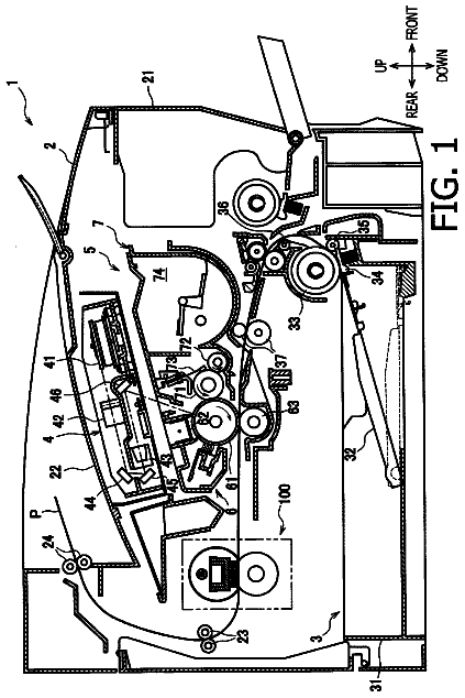
FIG. 1 is a sectional view showing a color printer according to an embodiment of the present disclosure.
FIG. 2 is a schematic view showing an electrical configuration in the color printer according to the embodiment of the present disclosure.
FIG. 3 is a flowchart showing operations of measurement condition decision in the color printer according to the embodiment of the present disclosure, and total current detection, resistance value measurement and transfer voltage correction of each primary transferring part of the color printer.
FIG. 4 is a flowchart showing operations of measurement condition decision in the color printer according to another embodiment of the present disclosure, and total current detection, resistance value measurement, and transfer voltage correction of each primary transferring part of the color printer.
FIG. 5 is a flowchart showing operations of measurement condition decision in the color printer according to a further embodiment of the present disclosure, and total current detection, resistance value measurement, and transfer voltage correction of each primary transferring part of the color printer.
FIG. 6 is a flowchart showing operations of measurement condition decision in the color printer according to a further embodiment of the present disclosure, and total current detection, resistance value measurement, and transfer voltage correction of each primary transferring part of the color printer.
Detailed description
First, an entire configuration of a color printer 1 (an image forming apparatus) according to an embodiment of the present disclosure will be described with reference to FIG. 1 . Hereinafter, for convenience of description, it will be described so that the front side of the color printer is positioned at the near side on a paper sheet of FIG. 1 .
The color printer 1 includes a roughly box-formed printer body 2 and, at a center part of the printer body 2 , an annular intermediate transferring belt 3 (a transferring belt) rotating in a predetermined direction is windingly stretched among a plurality of rollers. At a lower side of the intermediate transferring belt 3 , four image forming parts 4 ( 4 Y, 4 C, 4 M and 4 K) are provided for respective toner colors (e.g. four colors of yellow, cyan, magenta, black). The respective image forming parts 4 correspond to the respective colors of yellow (Y), cyan (C), magenta (M) and black (K) in sequential order from an upstream side in a rotation direction of the intermediate transferring belt 3 (a left side in the embodiment). Hereinafter, except a case of a description with specifying colors, reference codes “Y”, “C”, “M” and “K” are omitted with respect to the respective components corresponding to the toner colors. At a right end of the intermediate transferring belt 3 , a secondary transferring part 5 is provided and the secondary transferring part 5 is composed of a part of a right end side of the intermediate transferring belt 3 and a secondary transferring roller 6 .
In each image forming part 4 , a photosensitive drum 7 is rotatably provided, in other words, four photosensitive drums 7 ( 7 Y, 7 C, 7 M and 7 K) are disposed along the rotation direction of the intermediate transferring belt 3 . Around the photosensitive drum 7 , a primary transferring part 8 is disposed, in other words, four primary transferring parts 8 ( 8 Y, 8 C, 8 M and 8 K) are respectively provided with respect to the respective four photosensitive drums 7 ( 7 Y, 7 C, 7 M and 7 K). Each primary transferring part 8 is composed of a part of the intermediate transferring belt 3 and a primary transferring roller 9 . The primary transferring roller 9 is disposed to face to each photosensitive drum 7 across the intermediate transferring belt 3 . In other words, four primary transferring rollers 9 ( 9 Y, 9 C, 9 M and 9 K) of the four primary transferring parts 8 ( 8 Y, 8 C, 8 M and 8 K) are disposed to face to the respective four photosensitive drums 7 ( 7 Y, 7 C, 7 M and 7 K).
Moreover, at a left end of the intermediate transferring belt 3 , a cleaning device 10 cleaning the intermediate transferring belt 3 is provided and, at an upstream side from the cleaning device 10 in the rotation direction of the intermediate belt 3 , a pre-brush 11 is provided.
The cleaning device 10 consists of, for example, as shown in FIG. 2 , a cleaning roller 12 , such as a rotating brush, and a collecting roller 13 . The cleaning roller 12 is rotated while coming into contact with the intermediate transferring belt 3 to catch the remained toner on the intermediate transferring belt 3 . The collecting roller 13 collects the remained toner caught by the cleaning roller 12 . To the collecting roller 13 , a voltage of a reverse polarity (e.g. a negative polarity) of a polarity (e.g. a positive polarity) of the remained toner is applied.
The pre-brush 11 comes into contact with the intermediate transferring belt 3 to electrically charge and float the remained toner on the intermediate transferring belt 3 . To the pre-brush 11 , a voltage of the same polarity as the polarity (e.g. the positive polarity) of the remained toner is applied.
In an image forming process of the color printer 1 , an image of each color is formed by each image forming part 4 . At this time, in each image forming part 4 , first, the photosensitive drum 7 is electrically charged by a charger (not shown). Afterwards, on the basis of image data inputted from an external computer (not shown) or the like, the photosensitive drum 7 is exposed by an exposure device (not shown), and thereby, a electrostatic latent image is formed on the photosensitive drum 7 . The electrostatic latent image on the photosensitive drum 7 is developed for a toner image of each color by a development device (not shown). The toner image on the photosensitive drum 7 is primarily transferred to a surface of the intermediate transferring belt 3 by the primary transferring part 8 . The above-described operation is repeated by the four image forming parts 4 sequentially, and thereby, a toner image of full color (hereinafter, referred to as a color toner image) is formed on the intermediate transferring belt 3 .
In addition, in the image forming process of the color printer 1 , the color toner image is supplied to the secondary transferring part 5 by way of rotation of the intermediate transferring belt 3 . In the secondary transferring part 5 , a sheet is supplied from a sheet feeding cartridge (not shown) in accordance with a timing together with the color toner image and the color toner image on the intermediate transferring belt 3 is secondarily transferred to the sheet. Further, in the color printer 1 , the color toner image on the sheet is fixed by a fixing device (not shown) and the sheet having the fixed color toner image is ejected to an ejected sheet (not shown). Incidentally, the remained toner on the intermediate transferring belt 3 is cleaned and collected by the pre-brush 11 and the cleaning device 10 .
Next, an electrical configuration of the color printer 1 will be described with reference to FIG. 2 . The color printer 1 includes a controller 20 , a storage 21 , four transfer voltage applying parts 22 ( 22 Y, 22 C, 22 M and 22 K), a total current detecting part 23 , a current value comparing part 24 , a resistance value measuring part 25 , a transfer voltage correcting part 26 , a pre-brush voltage applying part 27 , a pre-brush current detecting part 28 , a measurement condition deciding part 29 , and a temperature sensing part 30 .
In the color printer 1 , as a measurement condition for carrying out total current detection by the four transfer voltage applying parts 22 and the total current detecting part 23 with respect to each primary transferring part 8 , for example, a case where a change quantity of the pre-brush current flowing through the pre-brush 11 from the last transfer voltage correction by the transfer voltage correcting part 26 to the present time (i.e. a time point of present detection of the pre-brush current) is equal to or more than a predetermined change threshold is defined. The measurement condition is also utilized, as shown in FIGS. 3 and 4 , as a measurement condition for carrying out resistance value measurement by the resistance value measuring part 25 and transfer voltage correction by the transfer voltage correcting part 26 . Incidentally, decision of the change quantity of a pre-brush current is carried out every time the pre-brush current detecting part 28 detects the pre-brush current. In a case where the transfer voltage correction is not yet carried out even once, such as a case of first detection of the pre-brush current, and the total current detection, the resistance value measurement and the transfer voltage correction may be carried out without deciding the change quantity of the pre-brush current, or alternatively, the resistance value measurement and the transfer voltage correction may be carried out without carrying out the total current detection. The four primary transferring parts 8 become detection subjects for the total current detection at the respectively different timings.
For example, the primary transferring part 8 of the detection subject may be switched every time images are sequentially transferred to the intermediate transferring belt 3 in accordance with a sequential order of disposition of the four primary transferring parts 8 , or alternatively, any one of the four primary transferring parts 8 may be specified or selected on the basis of a predetermined condition. A detection timing of the total current detection of the primary transferring part 8 of the detection subject is set to a timing while the primary transferring part 8 of the detection subject is over a space between sheets on the intermediate transferring belt 3 in a series of image forming operations employing the four primary transferring parts 8 (the four image forming parts 4 ), for example, is set to a timing immediately after transfer of the primary transferring part 8 .
The controller 20 consists of a CPU or the like. The controller 20 is connected to the storage 21 , the four transfer voltage applying parts 22 , the total current detecting part 23 , the current voltage comparing part 24 , the resistance value measuring part 25 , the transfer voltage correcting part 26 , the pre-brush voltage applying part 27 , the pre-brush current detecting part 28 , the measurement condition deciding part 29 , the temperature sensing part 30 , and other components included in the color printer 1 . The controller 20 is configured to be able to control each of these components.
The storage 21 consists of a ROM or a RAM or the like, and stores programs and data required to actualize the image forming process and a variety of other functions of the color printer 1 . Incidentally, although FIG. 2 illustrates the current value comparing part 24 , the resistance value measuring part 25 , the transfer voltage correcting part 26 and the measurement condition deciding part 29 separately from the storage 21 , these parts may be configured with the programs stored in the storage 21 and executed by the controller 20 .
The four transfer voltage applying parts 22 are provided to be associated with the four primary transferring parts 8 , respectively. Each transfer voltage applying part 22 is connected to each primary transferring roller 9 of each primary transferring part 8 to apply a voltage to each primary transferring roller 9 . For example, in a case of normal printing, in order to carry out primary transfer by each primary transferring part 8 , each transfer voltage applying part 22 applies a transfer voltage to each primary transferring roller 9 in a degree such that a predetermined target transfer current flows through each primary transferring roller 9 . The transfer voltage applied by each transfer voltage applying part 22 applies is a voltage value suitable for each primary transferring roller 9 and may be a voltage value different depending on each of the four transfer voltage applying parts 22 .
On the other hand, in a case of executing the total current detection with respect to the primary transferring part 8 of the detection subject, the four transfer voltage applying parts 22 apply a first measurement voltage to the primary transferring part 8 of the detection subject and apply a second measurement voltage different from the first measurement voltage to other primary transferring parts 8 . For example, the four transfer voltage applying parts 22 apply the transfer voltage (e.g. +1,000 V) as the first measurement voltage to the primary transferring part 8 of the detection subject and apply a zero voltage or a weak voltage (e.g. +50 V) of the same polarity as the transfer voltage as the second measurement voltage to the other primary transferring parts 8 at the detection timing when the primary transferring part 8 of the detection subject is over the space between sheets.
The total current detecting part 23 is connected to the four transfer voltage applying parts 22 .
The total current detecting part 23 is a detecting circuit of a current value configured to be common to the four primary transferring rollers 9 (the four primary transferring parts 8 ) to detect a total current value of the currents flowing through the four primary transferring rollers 9 . Incidentally, although the embodiment is described as to an example in which one total current detecting part 23 common to the four primary transferring rollers 9 is provided, the configuration of the total current detecting part 23 is not limited to this example. For example, two total current detecting parts 23 may be provided so that each total current detecting part 23 is connected to each two primary transferring rollers 9 and each current detecting part 23 detects a total current value of the currents flowing through each two primary transferring rollers 9 .
For example, in the case of executing the total current detection with respect to the primary transferring part 8 of the detection subject, the total current detecting part 23 detects the total current value of the currents flowing through the four primary transferring rollers 9 (the total current value associated with the primary transferring part 8 of the detection subject) at the detection timing associated with the primary transferring part 8 of the detection subject (the timing of applying the transfer voltage to the primary transferring roller 9 of the detection subject and applying the zero voltage or the weak current to other primary transferring rollers 9 ).
The current value comparing part 24 , with respect to each primary transferring part 8 (each primary transferring roller 9 ), inputs the total current value detected by the total current detection by the four voltage applying parts 22 and the total current detecting part 23 , calculates a current value difference between the total current value and a predetermined target current value and compares the current value difference and a predetermined differential threshold (e.g. the order of 2 μA). If the current value comparing part 24 , with respect to the primary transferring part 8 of the detection subject, decides that the current value difference between the total current value and the predetermined target current value is equal to or more than the predetermined differential threshold, the primary transferring part 8 is decided as a correction subject of the transfer voltage. The predetermined target current value of the primary transferring roller 9 (the primary transferring part 8 ) is determined in advance, for example, at a time of factory shipment or initial setting of the color printer 1 . If correction of the transfer voltage is carried out by the transfer voltage correcting part 26 , the target current value is updated and set by the total current value detected by the total current detecting part 23 at the time of the correction.
Incidentally, the current value comparing part 24 may store in the storage 21 or the like a correction execution trigger indicating whether or not correction of the transfer voltage is carried out, for each of the four primary transferring parts 8 (the four primary transferring rollers 9 ). With respect to each primary transferring part 8 (each primary transferring roller 9 ), the current value comparing part 24 sets the correction execution trigger to OFF in a case of deciding that the current value difference between the total current value and the predetermined target current value is less than the predetermined differential threshold. Alternatively, the current value comparing part 24 sets the correction execution trigger to ON in a case of deciding that the current value difference between the total current value and the predetermined target current value is equal to more than the predetermined differential threshold. After the current value comparing part 24 has set the correction execution trigger with respect to all of the four primary transferring rollers 9 , the resistance value measurement and the transfer voltage correction are carried out with respect to the primary transferring roller 9 corresponding to the correction execution trigger of ON.
The resistance value measuring part 25 measures a resistance value of each primary transferring roller 9 (each primary transferring part 8 ) on the basis of a voltage value applied by each transfer voltage applying part 22 , the total current value detected by the total current detecting part 23 and others. For example, the resistance value measuring part 25 executes the resistance value measurement measuring a subject resistance value of the primary transferring roller 9 (the primary transferring part 8 ) decided as the correction subject of the transfer voltage by the current value comparing part 24 on the basis of the total current value associated with the primary transferring part 8 of the correction subject detected by the total current detection.
Specifically, the resistance value measuring part 25 measures a subject current value (a transfer current) flowing through the primary transferring part 8 (the primary transferring roller 9 ) of the correction subject, on the basis of the total current value associated with the primary transferring part 8 of the correction subject, while the transfer voltage is applied. In addition, the resistance value measuring part 25 measures the subject resistance value of the primary transferring roller 9 of the correction subject on the basis of the transfer voltage and the subject current value, for example, by dividing the transfer voltage by the subject current value.
The transfer voltage correcting part 26 corrects the transfer voltage applied to each primary transferring roller 9 (each primary transferring part 8 ) by each transfer voltage applying part 22 to a voltage value in a degree such that the predetermined target transfer current flows. Specifically, the transfer voltage correcting part 26 calculates, with respect to the primary transferring part 8 of the correction subject, the corrected transfer voltage on the basis of the predetermined target transfer current and the subject resistance value, for example, by multiplying the predetermined target transfer current by the subject resistance value. Moreover, the transfer voltage correcting part 26 stores, in a case of carrying out the transfer voltage correction, the pre-brush current detected by the pre-brush current detecting part 28 , for subsequent decision of the measurement condition in the storage 21 or the like.
The pre-brush voltage applying part 27 is connected to the pre-brush 11 to apply a cleaning charge voltage of the same polarity as the polarity (e.g. the positive polarity) of the remained toner on the intermediate transferring belt 3 to the pre-brush 11 .
The pre-brush detecting part 28 is connected to the pre-brush voltage applying part 27 to detect the pre-brush current flowing through the pre-brush 11 at a predetermined timing. For example, as the predetermined timing, a timing, such as a time point after continuous printing of the order of 300 sheets has been carried out or a time point after the order of 12 hours has elapsed subsequent to use (activation) of the color printer 1 , may be set. In other words, as the predetermined timing, a timing when it is considered that a resistance value of the intermediate transferring belt 3 changes by a change of a temperature inside of the printer body 2 and a temperature of the intermediate transferring belt 3 may be set.
The measurement condition deciding part 29 decides in accordance with a predetermined measurement condition whether or not the total current detection by the four transfer voltage applying parts 22 and the total current detecting part 23 , the resistance value measurement by the resistance value measuring part 25 and the transfer voltage correction by the transfer voltage correcting part 26 should be carried out. For example, the measurement condition deciding part 29 decides a case where, after the transfer voltage of the primary transferring part 8 is corrected once or more by the transfer voltage correcting part 26 , the change quantity of the pre-brush current flowing through the pre-brush 11 detected by the pre-brush current detecting part 28 from the last transfer voltage correction by the transfer voltage correcting part 26 to the present time (i.e. a time point of present detection of the pre-brush current) is equal to or more than the predetermined change threshold (e.g. the order of 100 V), as the measurement condition for executing the total current detection, the resistance value measurement and the transfer voltage correction.
The temperature sensing part 30 senses a temperature in the vicinity of the intermediate transferring belt 3 or the four primary transferring parts 8 . Incidentally, although only one temperature sensing part 30 may be provided, temperature sensing parts 30 may be individually provided with respect to the intermediate transferring belt 3 and the respective four primary transferring parts 8 .
Next, the image forming operations (a printing operation) of the four image forming parts 4 and operations of the resistance value measurement and the transfer voltage correction of the primary transferring parts 8 in the embodiment will be described with reference to the flowchart of FIG. 3 .
Prior to the printing operation of the four image forming parts 4 , the cleaning charge voltage (e.g. the positive polarity) is applied to the pre-brush 11 by the pre-brush voltage applying part 27 . If the intermediate transferring belt 3 passes through the pre-brush 11 , the remained toner on the intermediate transferring belt 3 shifts to the same polarity as the cleaning charge voltage. Moreover, in the cleaning device 10 , the collecting roller 13 is electrically charged at the reverse polarity (e.g. the negative polarity) of the remained toner. If the intermediate transferring belt 3 passes through the cleaning device 10 , the remained toner on the intermediate transferring belt 3 is caught by the cleaning roller 12 and is efficiently collected by the collecting roller 13 of the reverse polarity of the remained toner.
At this time, by the pre-brush current detecting part 28 , the pre-brush current flowing through the pre-brush 11 is detected. Afterwards, in a case where the pre-brush current is equal to or more than the predetermined change threshold (step S 1 : YES), the total current detection by the four transfer voltage applying parts 22 and the total current detecting part 23 is executed. Incidentally, in a case where the pre-brush current is less than the predetermined change threshold (step S 1 : NO), normal printing is executed (step S 2 ).
In a case where the total current detection is executed, in the four image forming parts 4 , the image forming operation is first carried out at the yellow image forming part 4 Y and, at this time, the transfer voltage is applied from the yellow transfer voltage applying part 22 Y to the yellow primary transferring roller 9 Y (the yellow primary transferring part 8 Y), and then, primary transfer of the yellow toner image is carried out with respect to a predetermined printing position on the intermediate transferring belt 3 .
When the yellow primary transferring roller 9 Y is over the space between sheets after the primary transfer, the detection timing of the total current detection comes. At that time, the total current detection is executed with respect to the yellow primary transferring part 8 Y. Specifically, the transfer voltage is applied from the yellow transfer voltage applying part 22 Y to the yellow primary transferring roller 9 Y and the zero voltage or the weak current is applied from the respective transfer voltage applying parts 22 C, 22 M and 22 K to other primary transferring rollers 9 C, 9 M and 9 K. At this time, the total current value of the four primary transferring rollers 9 is detected by the total current detecting part 23 .
Subsequently, by the current value comparing part 24 , the current value difference between the total current value associated with the yellow primary transferring part 8 Y and the predetermined target current value is compared with the predetermined current threshold (step S 3 ). In a case where the current value difference is less than the predetermined current threshold (step S 3 : NO), the correction execution trigger of the yellow primary transferring roller 9 Y is set to OFF. On the other hand, in a case where the current value difference is equal to or more than the predetermined current threshold (step S 3 : YES), the yellow primary transferring roller 9 Y becomes the correction subject of the transfer voltage and the correction execution trigger of the yellow primary transferring roller 9 Y is set to ON (step S 4 ).
Next, the image forming operation is carried out at the cyan image forming part 4 C. At this time, the transfer voltage is applied from the cyan transfer voltage applying part 22 C to the cyan primary transferring roller 9 C (the cyan primary transferring part 8 C), and then, primary transfer of the cyan toner image is carried out with respect to the predetermined printing position on the intermediate transferring belt 3 .
When the cyan primary transferring roller 9 C is over the space between sheets after the primary transfer, the detection timing of the total current detection comes. At that time, the total current detection is executed with respect to the cyan primary transferring part 8 C. Specifically, the transfer voltage is applied from the cyan transfer voltage applying part 22 C to the cyan primary transferring roller 9 C and the zero voltage or the weak voltage is applied from the respective transfer voltage applying parts 22 Y, 22 M and 22 K to other primary transferring rollers 9 Y, 9 M and 9 K. At this time, the total current value of the four primary transferring rollers 9 is detected by the total current detecting part 23 .
Subsequently, by the current value comparing part 24 , the current value difference between the total current value associated with the cyan primary transferring part 8 C and the predetermined target current value is compared with the predetermined current threshold (step S 5 ). In a case where the current value difference is less than the predetermined current threshold (step S 5 : NO), the correction execution trigger of the cyan primary transferring roller 9 C is set to OFF. On the other hand, in a case where the current value difference is equal to or more than the predetermined current threshold (step S 5 : YES), the cyan primary transferring roller 9 C becomes the correction subject of the transfer voltage and the correction execution trigger of the cyan primary transferring roller 9 C is set to ON (step S 6 ).
With respect to the magenta image forming part 4 M and the black image forming part 4 K as well, similarly to the above-described yellow image forming part 4 Y and the cyan image forming part 4 C, the total current detection (steps S 7 to S 10 ) is carried out, and the correction execution trigger of the magenta primary transferring roller 9 M and the correction execution trigger of the black primary transferring roller 9 K are set.
Next, the resistance value measuring part 25 executes the resistance value measurement with respect to the primary transferring roller 9 of the correction subject of the transfer voltage (corresponding to the correction execution trigger of ON) (step S 11 ) and, on the basis of the total current value according to this primary transferring roller 9 , the subject resistance value of this primary transferring roller 9 is measured. In addition, the transfer voltage correcting part 26 executes the transfer voltage correction with respect to the primary transferring roller 9 of the correction subject of the transfer voltage (corresponding to the correction execution trigger of ON) (step S 11 ) and, on the basis of the subject resistance value measured as described above, the transfer voltage applied from the transfer voltage applying part 22 to this primary transferring roller 9 is corrected to a voltage value in a degree such that the predetermined target transfer current flows.
According to the embodiment, as described above, the color printer 1 (the image forming apparatus) includes: the annular intermediate transferring belt 3 (the transferring belt) rotating in the predetermined direction; a plurality of photosensitive drums 7 ; the plurality of primary transferring parts 8 (the plurality of primary transferring rollers 9 ); the transfer voltage applying parts 22 ; the resistance value measuring part 25 ; the cleaning device 10 ; the pre-brush 11 ; the pre-brush current detecting part 28 ; and the transfer voltage correcting part 26 . The photosensitive drums 7 are disposed along the rotation direction of the intermediate transferring belt 3 . The primary transferring parts 8 transfer the image formed on the respective photosensitive drums 7 to the intermediate transferring belt 3 . The transfer voltage applying parts 22 apply voltages to the respective primary transferring parts 8 . The resistance value measuring part 25 measures the subject resistance value of the primary transferring part 8 . The cleaning device 10 collects the remained toner on the intermediate transferring belt 3 . The pre-brush applies the cleaning charge voltage of the same polarity of the remained toner on the intermediate transferring belt 3 at the upstream side from the cleaning device 10 in the rotation direction of the intermediate transferring belt 3 . The pre-brush current detecting part 28 detects the pre-brush current flowing through the pre-brush 11 . The transfer voltage correcting part 26 corrects, on the basis of the subject resistance value of the primary transferring part 8 measured by the resistance value measuring part 25 , the transfer voltage with respect to the primary transferring part 8 . In addition, the case where the change quantity of the pre-brush current detected by the pre-brush current detecting part 28 from the last transfer voltage correction by the transfer voltage correcting part 26 to the present time (i.e. a time point of present detection of the pre-brush current) is equal to or more than the predetermined change threshold is set as the measurement condition. If the measurement condition is satisfied after the transfer voltage of the primary transferring part 8 is corrected regardless of the measurement condition (e.g. at the first time), the resistance value measuring part 25 executes the resistance value measurement measuring the subject resistance value of the primary transferring part 8 and the transfer voltage correcting part 26 executes the transfer voltage correction correcting the transfer voltage of the primary transferring part 8 .
Moreover, according to the embodiment, the color printer 1 includes: the total current detecting part 23 to detect the total current value of currents flowing through the plurality of primary transferring parts 8 . If the above-described measurement condition is satisfied, the total current detection is executed so that the transfer voltage applying part 22 applies the first measurement voltage to one primary transferring part 8 (the primary transferring part 8 of the detection subject) in the plurality of primary transferring parts 8 and applies the second measurement voltage to other primary transferring parts 8 and the total current detecting part 23 detects the total current value, and the resistance value measuring part 25 executes the resistance value measurement with respect to the one primary transferring part 8 (the primary transferring part 8 of the detection subject) on the basis of the total current value detected by the total current detection, and the transfer voltage correcting part 26 executes the transfer voltage correction with respect to the one primary transferring part 8 .
Further, according to the embodiment, the transfer voltage applying part 22 applies, when the total current detection is executed, the transfer voltage, as the first measurement voltage, to the primary transferring part 8 of the detection subject and applies the zero voltage or the weak voltage of the same polarity as the transfer voltage, as the second measurement voltage, to the other primary transferring parts 8 . In a case where it is decided that the current value difference between the total current value detected by the total current detection and the predetermined target current value is equal to or more than the predetermined differential threshold, the resistance value measuring part 25 executes the resistance value measurement and the transfer voltage correcting part 26 executes the transfer voltage correction.
The description continues in the full USPTO document.
 Lapsed, fee not paid11 drawings