 Lapsed, fee not paid4 drawings
Cameras, Displays & Optics · US 9,958,696 B2
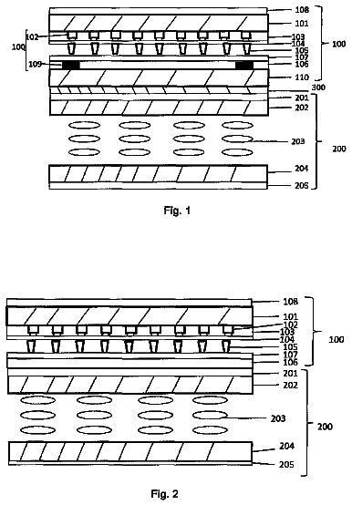
Stereo display device and method manufacturing the same
The present invention provides a stereo display device and a method for manufacturing the same.
US 9,958,700 B2 · Assignee: EASTMAN KODAK COMPANY · Inventors: Lofftus; Kevin D. et al.
Sheet 1 of 4 from the published document. All sheets in the USPTO PDF
An optical modulator ( 12 ) for speckle suppression in a laser projection system includes a first planar transparent conductor ( 20 ); a second optionally transparent planar conductor ( 26 ); a diffusing element ( 22 ) disposed between the first and second conductor; and an alternating voltage applied across the first and second conductors creates in-plane movement or distortion in the diffusing element to reduce laser speckle.
When laser light is reflected from a surface such as paper, a wall or a projection screen, a high contrast, fine scale granular pattern called laser speckle is seen by an observer looking at the illuminated spot. From the earliest days of lasers, the cause of speckle was recognized to be the fact that most materials are randomly rough on the scale of an optical wavelength, with the exception of highly polished surfaces such as mirrors. Upon reflection from a rough surface, different facets contribute elementary wavelets with slightly different optical path lengths that interfere with each other upon propagation, producing the high contrast, fine scale speckle pattern. The statistics of the light intensity in the speckle pattern can be related to the statistics of the rough surface, the size of the scattering spot, the wavelength of the light, and other parameters of the illuminating beam
All 4 drawing sheets from the published document, cropped to the drawing.
What the patent claimed, word for word. All of it is now free to use.
The invention relates in general to laser projection of digital images and in particular to reducing speckle in the projected image.
When laser light is reflected from a surface such as paper, a wall or a projection screen, a high contrast, fine scale granular pattern called laser speckle is seen by an observer looking at the illuminated spot. From the earliest days of lasers, the cause of speckle was recognized to be the fact that most materials are randomly rough on the scale of an optical wavelength, with the exception of highly polished surfaces such as mirrors. Upon reflection from a rough surface, different facets contribute elementary wavelets with slightly different optical path lengths that interfere with each other upon propagation, producing the high contrast, fine scale speckle pattern. The statistics of the light intensity in the speckle pattern can be related to the statistics of the rough surface, the size of the scattering spot, the wavelength of the light, and other parameters of the illuminating beam. The speckle phenomenon is not confined to visible light, and is well known in radar and other regions of the electromagnetic spectrum. In fact, speckle is a fundamental part of any wave or field phenomenon, and is also well known in applications such as ultrasound, and even in the study of gravitational fields in astrophysics.
Because of the sensitivity of laser imaging systems to speckle, it is useful in the metrology or characterization of rough surfaces, or other scattering objects such as small particles. In image formation, however, speckle is a noise source that interferes with the image or signal information, and must be reduced or eliminated. In particular, in laser projection systems used in near-to-eye, office or theatre environments, it is critical that speckle be minimized so that it does not interfere with the clarity or enjoyment of the image. Many methods have been suggested in the prior art to reduce speckle in projection imaging systems. They can be divided roughly into two classes: 1) methods pertaining to reduction of speckle at the projection source and 2) methods pertaining to reduction of speckle at the projection screen or surface where the final image is formed. All classic methods of speckle reduction involve an averaging process, as explained in the text “Speckle Phenomena in Optics”, by J. W. Goodman, Roberts and Co., Englewood Colo., 2007. That is, a number of statistically independent speckle patterns must be either simultaneously averaged, or averaged within a time period shorter than the response time of the human eye. Methods reviewed by Goodman include averaging over wavelength (increasing the bandwidth of the optical system), averaging over time (using a moving diffuser or changing phase mask in the projector) and overdesign of the projection optics relative to the eye (averaging many projector blur spots within a single eye blur spot).
A successful laser projection system can apply multiple methods of speckle reduction, at both source and screen, since most methods fail to eliminate speckle entirely in a single step. Speckle is characterized by the mean intensity <I> and standard deviation σ.sub.I of its intensity (I), which are combined into a single metric of speckle contrast C:
C = σ I .Math. I .Math. , ( 1 ) where 0≤C≤1. This can also be expressed as a percent. Each method of speckle reduction is as good as the effective number of statistically independent speckle patterns it generates. Here “effective” means the number of statistically independent patterns generated within the integration or response time of the eye, detector or camera used to observe them. If reduction method i generates N.sub.i independent patterns, it contributes a factor 1/√{square root over (N.sub.i)} to the overall speckle reduction. If M methods are used in total, the overall speckle reduction factor R is
R = [ .Math. i = 1 M N i ] 1 / 2 , ( 2 ) so that the reduced speckle contrast is C′=C/R.
As mentioned earlier, one method of generating multiple speckle patterns is to use a moving diffuser or changing phase screen in projector, or in the optical beam between the projector and screen. In a well-known method, a rotating diffuser or phase plate is placed in the beam of a projection system either in the projection optics, or between the projector and the screen, so that the imaging beam suffers random phase delays across its extent. A fixed diffuser would merely lead to a slightly different speckle pattern than if it were absent. However, by moving the diffuser plate or phase plate, a series of speckle patterns is created. If the plate is moved rapidly and through a sufficient distance, enough independent speckle patterns are generated to reduce the overall noise.
Other methods of speckle reduction between the projector and screen are directed towards reducing the bulk of the diffuser mechanism. For example, U.S. Pat. No. 8,500,287 (Moussa) describes a device based on a piezoelectric actuator, in which a diffuser is fixed inside a vibrating metallic frame. The frame moves the diffuser laterally, i.e. in the plane of the frame. In another example, U.S. Pat. Nos. 8,553,341 and 8,902,520 (both to Aschwanden) describe an electroactive optical device suitable for inclusion in the optical beam between the projector and the screen. The device is comprised of a pre-stretched polymer film with electrodes on both surfaces, and a rigid optical element (such as a diffuser) connected to either surface or the polymer film. The application of a voltage to the electrodes displaces the optical element along the plane of the polymer film, due to Coulomb forces. In-plane displacements of a diffuser or phase plate are used to create a series of independent speckle patterns. The in-plane displacements by be rotational or lateral in the x and y directions. Out-of-plane movements in the z direction are disclosed in U.S. Pat. No. 8,500,287 as bending the plate across the full width of the image beam causing image distortion and loss of image sharpness as the speckle reduction averaging process also averages the distortions. Problems with the placement of moving diffusers into the beam optics include scatter from the diffuser reducing the sharpness of the focused image, or creating haze in the image. Reduction of the diffusive properties of the diffuser to reduce haze in the image can render the diffuser ineffective in reducing speckle as demonstrated in comparative EXAMPLE 1. While the loss of image sharpness can be eliminated by positioning of the diffuser and optical modulator before the beam-shaping element of an imaging system and focusing the dispersed beam onto the beam-shaping element, the effect of the optical modulator is reduced or eliminated as demonstrated in comparative EXAMPLE 2. The loss of image sharpness and hazing cause by diffusers can be reduced by placing a diffuser closer to the screen, or nearly in contact, but then the diffuser becomes very large and hard to move laterally.
This leads to the second class of speckle reduction methods, directed towards improvements to the projection screen. In one example, U.S. Pat. No. 6,122,023 (Chen et. al.) describes a liquid crystal projection display screen constructed in a highly scattering state. The display includes a plurality of liquid crystal spheres. When no voltage is applied, the medium is highly scattering and the screen is opaque. When a voltage is applied, the liquid crystal molecules are aligned and the light is transmitted. When the voltage is varied with a 60 Hz signal, the spheres vibrate, causing a varying speckle pattern which the eye averages. In another example, U.S. Pat. No. 8,724,218 (Curtis et. al.) describes speckle reduction using mechanical vibration of the screen. Devices near, but not in contact with, the screen generate acoustic or electromagnetic waves that couple to the screen and produce mechanical vibrations, creating a changing speckle pattern. The screen vibration may occur in all of the x, y and z directions, that is to say movement in the x and y directions are lateral movements in the plane of the screen and movement in the z direction are axial movements perpendicular to the screen. Such mechanical vibration methods must be carefully tuned to avoid standing wave patterns and regions of uneven or zero vibration. None of the speckle reduction methods cited report quantitative performance results, or discuss their potential impact on image sharpness. There is still a need, therefore, for additional methods of laser speckle reduction in projection systems.
An active diffuser for laser projection systems comprising a separation layer between two planar conductors and a diffuser material disposed upon at least one of the surfaces of one of the conductors or dispersed throughout the separation layer whereby the separation layer is either compressible or causes axial deformation in one of the conductors when a voltage is applied across the two conductors. At least one of the planar conductors is transparent. Applying an alternating voltage across the conductors expands and compresses the separation layer, creating a “moving diffuser”. This action reduces undesirable static interference patterns that create multiple light paths known as laser speckle.
In a preferred embodiment of the present invention, the moving diffuser is placed close to, or nearly in contact with the screen thereby retaining a sharp image without haze. The screen may be front-lit when viewed from the same side as the projector or back-lit when viewed from the opposite side as the projector.
A feature of the present invention is movement of the diffuser along the axis of the projected image without lateral movement that may cause standing wave patterns with no speckle reduction.
The present invention may be combined with other methods of speckle reduction to increase the overall reduction of speckle.
These and other objects, features, and advantages of the present invention will become apparent to those skilled in the art upon a reading of the following detailed description when taken in conjunction with the drawings wherein there is shown and described an illustrative embodiment of the invention.
FIG. 1 is a perspective view of a laser projection system;
FIG. 2 is a schematic diagram of an active diffuser optical modulator;
FIG. 3 a is a side view of an active diffuser optical modulator when separation layer is compressed;
FIG. 3 b is a side view of an active diffuser optical modulator when separation layer is not compressed;
FIG. 4 is a schematic diagram of a system for the quantitative measurement of subjective laser speckle.
The present invention is described below in the environment of a laser projection system.
FIG. 1 represents a perspective view of a laser projection system according to one embodiment. A coherent light source such as a laser projector 10 projects an image through active diffuser optical modulator 12 placed between the projector and a projection screen 14 . FIG. 2 is a schematic diagram of one embodiment of the present invention whereby the diffuser element 22 is placed between the first transparent conductor 20 and the separation layer 24 . The second conductor 26 is placed between the separation layer 24 and the projection screen 14 . An alternating voltage is applied between transparent conductors 20 and 26 to create an attractive Coulomb force between the conductors. FIG. 3 a is a side view of an active diffuser optical modulator 12 when separation layer 24 is a compressible layer and is compressed by attractive Coulomb force between the conductors 20 and 26 when a voltage is applied. FIG. 3 b is a side view of an active diffuser optical modulator 12 when the compressible separation layer 24 is expanded to its original thickness when no voltage is applied between the conductors 20 and 26 .
The conductors 20 and 26 may comprise substantially transparent conductive layers such as metal mesh or transparent conductive layers made of such materials at tin doped indium oxide also known as indium tin oxide or ITO, aluminum zinc oxide also known as AZO, or a conductive polymer (e.g. PEDOT:PSS poly(3,4-ethylenedioxythiophene) polystyrene sulfonate) disposed upon a transparent support. The support for first conductor 20 must be flexible such as PET films, while that of second conductor 26 may be relatively rigid such as glass, polymer sheets, etc.
The diffuser element 22 may be disposed upon the outside of one of the conductors as well. The diffuser moves with the surface of one of the conductors that is free to move while the other conductor is rigid.
In one embodiment, the separator layer may be a micro-patterned elastomer to enhance compressibility of the separation layer. The force generated by the voltage is distributed over a smaller area resulting in greater movement in a compressible separation layer have the same Young's modulus.
In another embodiment, the compressibility of the separator layer is enhanced by random placement of isolated beads on the separation layer. Additionally, the compression of the separator layer is not constrained. Rather than compress uniformly, the separation layer deforms around the beads into the air gap created between the conductor and the separation layer by the beads resulting in greater movement at lower applied force.
In another embodiment, the separator layer is an air gap created by random placement of isolated spacer beads between the conductors. In this embodiment, the spacer beads act as tent-poles around which the support film of the transparent conductor elastically deforms when voltage is applied across the conductors. The diffuser elements are disposed on one or both of the surfaces of the conductor that deforms and are moved by the deformation of the conductor support.
In yet another embodiment, the separator layer is an air gap created by random placement of isolated spacer beads on both sides of a flexible support forming an interlayer that is placed between the transparent conductors. The diffuser elements are disposed on one or both of the surfaces of the conductor that deforms the spacer beads between it and the interlayer. Additional diffuser elements may be disposed on one or both of the surfaces of the flexible film which deforms around the spacer beads as the Coulomb forces press the two conductors together.
In yet another embodiment, the second transparent conductor 26 is integrated with the projection screen 14 . For example, a conductive polymer such as PEDOT:PSS may be coated over the reflector screen, or included within the reflective coating of the reflector screen.
In yet another embodiment, the second conductor is placed behind the reflective screen. It is desirable to have the reflective screen as thin as possible to minimize the separation between the conductors thus minimizing the voltage required to achieve the Coulomb force needed to move the diffuser sufficient for speckle reduction. One example is white ink coated over metalized polymer film. Another example is a reflective screen made of light scattering components like white pigments such as titanium dioxide and zinc oxide or structural pigments such as porous polymer particles or synthetic mica flakes and a conductive polymer with substantial resistance coated over a highly conductive surface such as a metalized polymer film thereby bringing the second conductor closer to the first while minimizing the resistance and resulting in lower voltages needed to achieve high Coulomb forces.
In yet another embodiment, the projection screen is a rear or back-lit projection screen with the active diffuser element facing the projector. In yet another embodiment, the projection screen is a back-lit projection screen with the active diffuser element facing the observer.
A reflector screen in FIG. 1 or 2 demonstrates an embodiment wherein light scattering particles or voids filled with liquid or gas are placed within the compressible layer and move independently as the layer is compressed to provide additional independent speckle patterns to be average over the cyclic compression further reducing speckle.
A diffuser element may be any element that changes the path of light transmitted through the element and may include randomly patterned and micro patterned transparent films that refract light, coatings of isolated beads on transparent film that act as planoconvex lenses, and coatings of white pigments with high refractive indices such as titanium dioxide and zinc oxide or white structural pigments such as porous polymer particles or synthetic mica flakes that scatter light. Movement of the diffuser results in different paths for the light from the projector to the reflector and to the observer.
Axial movement of the diffuser element as a plane in a direction parallel to the laser source requires a significant displacement to produce a change in the speckle pattern. Movement of the diffuser in this manner produces a change in the path length of the light on two sides of a highly acute triangle resulting in nearly the same overall path length to reach the observer. Movement of about 2 microns is needed to create a half wavelength change in the path length for the conditions cited in the examples below where the observer is placed at 20 degrees from the center line of the laser beam. The triangle becomes more acute as the observer is moved closer to the center light path and greater movement is needed to effect the same speckle reduction. For example, movement of about 3 microns is needed for an observer at 15 degrees and 7 microns for 10 degrees. The number of independent speckle patterns produced by movement of the diffuser should be proportional to the distance moved. Given this, Equation
predicts the speckle reduction factor R to be is linear with respect to the square root of the Columbic force applied. The Columbic force is proportional to the square of the applied voltage using a parallel plate geometry thus Equation
predicts that the speckle reduction factor R is linear with respect to applied voltage.
The diffuser movement needed to produce sufficient change in the light path length to affect the speckle pattern can be reduced by providing discrete regions through which the path of the projected and reflected light is not changed by the diffuser element in close proximity that is less than the blur spot size of the observer to regions where the light path is changed by the discrete active diffuser element. Micro patterned transparent films, coatings of isolated bead on transparent film, and half-tone printed ink with white pigments are particularly useful as such diffusers. In one embodiment, the isolated beads may occupy 10-70 area % of the transparent film. The area coverage of isolated diffuser beads in discrete active diffusers is estimated from the projected area of the surface weighted mean bead diameter.
For diffuser beads that scatter light in the Mie region, the disturbance of the light is approximately proportional to the projected area of the bead. Thus it is appropriate to characterize the ability of a bead coating to disturb the light path in a diffuser by the surface weighted mean diameter of the beads in the coating.
Surprisingly, the diffuser movement needed to produce a change in the speckle pattern may be also further reduced by distorting the diffuser. The distorted diffuser changes the angle of the light path projected from any point on the diffuser that changes the light path by refraction resulting in projection to a different observer. For areas of the diffuser through which the path of the projected and reflected light is not changed by refraction or scattering, no change in path light in generated by axial movement resulting projection of that light to the same observer. The combination of this light with the same path with light scattered or refracted from different paths as the distortion changes results in a different speckle pattern that reduces speckle when average over the response time of the observer.
There is no expectation of the number of independent speckle patterns produced by axial distortion of the diffuser. In fact, when the active diffuser comprises discrete areas of high reflectivity positioned on a regular pattern with high transparency in other area of the diffuser as is the case in invention EXAMPLES 2 and 6C, the speckle reduction factor R is linear with respect to the square root of the applied voltage. Surprisingly, when the discrete areas are randomly placed porous beads of moderate reflectivity, the value of R is directly linear with respect to the applied voltage. This is also the case for diffusers with either continuous or discrete areas of low reflectivity.
Distortion of the active diffuser may be achieved in a number of manners. Distortion may be provided by a conductor patterned with two or more inter-digitized conductive traces whereby the phasing and amplitude of the voltages applied to each trace are independent. Additionally, a solid compressible layer is more readily deformed in small scale if constant volume is maintained and volume from under the trace to which voltage is applied to may be displaced to under traces where voltage is not applied. The spacing of the conductive traces must be less than the resolution of the human eye to effect a reduction in speckle. The resolution of the human eye varies from individual to individual and with the lighting levels of the viewing environment. The angular resolution that constitutes 20/20 vision in a well lit room is about 1 arcminute at a gain of 10%. In a darkened theater, the pupil dilates and the modulation transfer function (MTF) the eye degrades by about a factor of 3 as the pupil dilates from 2 mm to 6 mm (Andrew B. Watson, “A formula for the mean human optical modulation transfer function as a function of pupil size,” Journal of Vision , May 2013, Vol. 13, 18). Spacing between conductive traces of 700 microns would result in two conductive traces within 1 arcminute for a viewer seated 5 meters from the projection screen.
Another method of distorting the moving diffuser is to provide hard domains within a compressible separation layer. The amount of movement in-plane of the diffuser will vary with the compressibility of the separation layer as voltage is applied across the two conductors to provide a compression by Coulomb forces.
A different form of distortion may be achieved by integrating the diffuser and the compressible layer. Regions of different refractive index within the compressible separation layer may act as the diffuser element by scattering light. As the layer is compressed, the spacing between these scattering regions throughout the layer changes resulting in different paths of light being projected to the observer. A compressible separation layer with diffuser properties may be obtained with single phase materials having density variations that scatter light such as translucent silicone elastomers. Another method is to provide diffuser properties in the compressible separation layer is with two phase materials where the phases have different refractive indices. The phases may both be continuously intertwined or vesicular or one phase may be discrete regions within the continuum of the other phase. Of particular use is discrete phases comprising a highly deformable material such as a liquid or gas that changes the light scattering properties arising from the shape of the discrete phase.
The compressible layer may be made of any elastomeric material that is transparent and include cross linked silicone, acrylates formulated to provide a high compressibility or low Young's Modulus. The compressibility may be enhanced by a foamed elastomeric material (U.S. Pat. No. 8,410,239 (Blanc et al.)) that also provide a diffuser component. Another method to enhance compressibility of a separation layer is to distribute the Coulomb force generated by the applied voltage across the conductors over a smaller area thereby producing a larger strain in the elastomer resulting in a greater movement of the diffuser element. The force may be concentrated through isolated tent poles of the elastomer by micro-patterning a continuous layer of the elastomer, placing a non-continuous application of elastomer on a support with discrete areas smaller than the required resolution, or distributing hard particles across the surface of the elastomer. The latter method provides both planar movement as well as distortion for flexible conductors and diffuser elements that are in contact with the particles.
The air gap surrounding the hard beads disposed upon the reflector and the second conductor may be considered a compressible separation layer provided the first conductor and diffuser elements are flexible and readily distort. The spacing between the beads may be adjusted to tune the movement and distortion of the diffuser element. Low area coverage of beads are preferred but must be sufficient to prevent the first conductor support from contacting the second conductor and reflector possibly resulting in a short circuit, arcing, or possible “freezing” of the optical modulator, wherein the van der Waals forces of the contact are greater than the restoring force provided by the flexible supports for the first conductor and diffuser elements.
For optical modulators where polydispersed spacer beads are used to form a separation layer, increasing the distortion of the first conductor and diffuser support caused the support to contact the smaller pacer beads and increases the contact area which may lead to localized freezing of the modulator. Beads with a small width index and preferably mondispersed will minimize this freezing effect.
A flexible interlayer of transparent polymer film may be disposed between two layers of hard beads to provide a compressible separation layer for rigid first conductor and diffuser elements. The beads must be randomly disposed on either side at low coverages so that few beads are near the same spot on opposite sides of the flexible interlayer. This flexible interlayer may also serve as a diffuser element to enhance speckle reduction by providing light path changes from refraction and scattering sites that move relative to both the primary diffuser and the reflector. Optimal speckle reduction performance occurs for more open areas in discrete active diffuser through which the path of the projected and reflected light is not changed by refraction or scattering are needed on both the primary diffuser and the flexible interlayer than would for a primary diffuser alone. The observed speckle reduction factor may have a second linear region of lower slope when the flexibility of the interlayer is greatly different than that of the outer diffuser support when applied force exceeds the limit movement or distortion of the more flexible layer. The uniformity of the speckle reduction may still be improved in these conditions when the interlayer is the more flexible material as well as preventing localized freezing of the active diffuser optical modulator due contact to too many areas as described above.
The invention has been described in detail with particular reference to certain preferred embodiments thereof, but it will be understood that variations and modifications can be effected within the scope of the invention.
In the characterization of speckle, some authors distinguish between objective and subjective speckle. Speckle patterns are said to be objective when no imaging is involved in their detection, for example, when measured by an optical sensor without a lens. (Even in this case, however, it must be pointed out that the result depends on the size of the sensor elements.) Speckle patterns are said to be subjective when an imaging system is involved in the formation of the final speckle pattern. Such imaging systems may include the human eye, or an electronic camera used for measurement purposes. The statistics of the speckle intensity are sensitive to the parameters of the imaging system used, such as the pupil size, focal length and area of the sensor elements. The perceived contrast of speckle as seen by the human eye is likewise sensitive to the same optical parameters of the human eye. As discussed by Roelandt et. al. in the journal article “Standardized speckle measurement method matched to human speckle perception in laser projection systems”, published in Optics Express Vol. 20, No. 8, 8770-8783 (2012), it is necessary to match the optical parameters of the measurement system to those of the human eye when correlating physical measurements to the judgements of observers. At a minimum, the parameters of the measurement system should be fixed and clearly stated, which is the approach taken here.
Following Roelandt et. al., the average size of the speckles in a lens-produced image is given by:
A c = 4 λ 2 ( f / # ) 2 π , ( 4 ) where λ is the wavelength and (f/#) is the f-number of the lens (focal length divided by clear aperture). The f-number of the measuring lens determines the observed speckle size relative to the sensor pixel area. If the speckle size is smaller than the sensor pixel size, averaging over speckles (and hence speckle reduction) will occur relative to the objective value of speckle contrast C. The speckle contrast is reduced by the ratio √{square root over (A.sub.p/A.sub.c)}, where A.sub.p is the area of a camera pixel, compared to the objective value. Therefore it is desirable that the speckle size in the image be larger than the sensor size, so that this ratio remains less than one.
FIG. 4 is a schematic diagram of a system 400 for the quantitative measurement of subjective laser speckle. Coherent light from a laser 405 is directed through a lens 410 , which brings the beam to a focus through a pinhole 415 . This is a standard technique for filtering a laser beam to remove spatial nonuniformities. The beam is then further directed through a collimating lens 420 , which produces a nearly parallel beam of light focused at infinity, and directed towards an optical modulator 430 and reflection screen 435 . Adjustable iris 425 controls the size of the scattering spot on the optical modulator 430 and screen 435 . The speckle pattern is recorded by an electronic camera 440 , placed at an angle to the optical axis of the illumination beam. The optical modulator 430 provides reduction of the objective speckle seen by the camera 440 when the modulator is activated.
The electronic camera 440 used in this work was a Point Grey Research GRAS-03K2M 640×480 pixel monochrome camera, operated at 60 frames per second (fps). It was fitted with an Edmund Optics machine vision lens with a focal length of 12 mm, set to f/16 at a working distance of approximately 180 mm at 20 degrees from the center line of the laser beam. The pixel size of the sensor in the Point Grey camera is 7.4 μm. The resulting resolution was 250 microns per pixel. Using Eq.
with λ=0.633 μm, the speckle reduction ratio for measurement is √{square root over (A.sub.p/A.sub.c)}=0.65. This compares favorably with the ratio of 0.6423 computed by Roelandt et. al. (here adjusted for the wavelength difference of 0.532 μm in their work vs 0.633 μm in our work) for human retinal mosaic pixel area and the typical speckle size in a cinema environment.
Optical modulators constructed from various components were evaluated at different applied peak-to-peak voltages using a sine waveform driven at 60 Hertz. The wave form had little effect on the speckle reduction provided the same peak-to-peak voltages were applied and the movement of the diffuser could respond at the frequency. A slight loss in performance was observed for square and triangle waveforms and for higher frequencies but not for saw tooth waveforms. Frequencies between 60 Hertz and that of the time resolution of the eye (about 40 Hertz caused aliasing with the imaging camera operated at 60 frames per second (fps).
One hundred frame video files were collected by the electronic camera 440 for each test condition. The resulting videos were processed using a 3 frame running average to reduce the impact dark noise and remove the effects of any shifts in the optical modulator on the speckle pattern. The 3 frame running averages were rescaled by the local beam intensity of the filtered image using a 30×30 pixel Gaussian filter having a standard deviation of 7 pixels. The first and second moments over the beam area were accumulated from which the mean C and standard deviation S of the speckle contrast were calculated.
It was found that the performance of an optical modulator could be characterized by a linear response of the static speckle contrast C divided by the active speckle contrast C, hereafter known as the speckle reduction factor R, to either the peak-to-peak voltage (p=1 in Table V) or the square root of the peak-to-peak voltage (p=½ in Table V). The slope of R versus the electric field (peak-to-peak voltage divided by the spacing) characterizes the compressibility of the separation layer giving rise to the movement of the diffuser. The intercept of R versus peak-to-peak voltage was found to be influenced by several factors such aliasing between applied voltage and camera frequency, easy movement and deformation at low applied voltage, particulate contamination or air gaps between layers or interaction from two or more refractions from flexible surfaces. The quality of the optical modulator to reduce speckle was characterized by S the standard deviation of the speckle contrast C. The results of example optical modulators are summarized in Table V below.
The resolution of an optical system may be expressed the frequency at a given gain for system MTF. It is customary to multiply the MTF gains of each optical element of an imaging system to derive the system MTF. While this applies to light collected on a detector passed through a series of lenses or other linear optical devices, it is not certain how the MTF of a non-linear device such as an active diffuser modulator could be separated from the MTF of the reflector screen. At best one can treat the screen as a resolution chart viewed by the camera and estimate the distance at which the screen resolution is greater than that of the human eye.
The impact of the active diffuser optical modulators on the image resolution were subjectively evaluated using a transmission square wave resolution target placed 360 mm from the modulator. While diffraction from the target prevented MTF analysis of the images, visual inspection showed improved edge sharpness resulting in a perceived image resolution improvement when the modulator was active. In some cases, the MTF was estimated using a method similar to ISO 12233, which uses a slanted edge, by placing a razor blade in the beam 60 mm from the optical modulator with the razor edge at an angle of 5.7 degrees to the camera pixels. The resulting MTF was fit with a second order polynomial of the frequency to estimate the frequencies at MTF gains of 50% (MTF50) and 20% (MTF20). Image speckle, spacer beads, and diffuser beads produced strong beat patterns that were interpreted as higher MTF values for some the higher frequencies and in some case a MTF20 could not be estimated. Resolution is typically cited at a gain of 10% but no estimate could be made of the frequency for MTF at 10% gain due to noise induced by speckle. Equivalent resolution of the human eye can be taken from Andrew B. Watson, “A formula for the mean human optical modulation transfer function as a function of pupil size,” Journal of Vision, May 2013, Vol. 13, 18 as MTF50's of 13 cycles/degree for pupil dilation of 2 mm and 3 cycles/degree at 6 mm pupil dilation and MTF20's of 40 cycles/degree for pupil dilation of 2 mm and 13 cycles/degree at 6 mm pupil dilation. From this, the distance from the screen can be estimated at a given limit of resolution of the human eye.
Components used to construct example optical modulators are classified as reflectors, conductors, separators, and diffusers and are described as follows:
Reflectors:
Reflectors that were illuminated from the front were either a polyurethane-coated fiberglass screen (VuliteMax), or coatings on nickel plated PET film with a wet thickness of 4 mils of a white ink mixture comprising consisting of equal parts of SunStrato WB MSquared white ink available from Sun Chemical, Extender DPQ-173 available from Sun Chemical, and a diluent comprising a water solution of 4% by weight isopropyl alcohol, 2% by weight 1-methyl-2-pyrrolidone, and 2% by weight N,N-dimethylthanolamine. Backlit reflectors were a wet thickness of 4 mils using the same white ink mixed at 1 part to 11 parts extender and 12 parts diluent coated on transparent support. The front-lit reflectors were held to a rigid steel frame with rare earth magnets providing an immobile reflector surface. The back-lit reflectors were held to a steel frame with a hole to pass the laser beam resulting in a flexible reflector that moved when the optical modulator was active.
Conductors:
Conductors consisting of both transparent and opaque nature were used. Transparent conductors used were PEDOT:PSS coated PET and copper gridded PET. The PEDOT:PSS conductor components consisted of 6 mil PET coated with PEDOT:PSS on one side available as Kodak HCF-150 (Cat. No. 190-7591) and 2.5 mil PET coated at 55 C with Heraeus Clevios PEDOT:PSS diluted by equal weight with water and have 0.05% fluorosurfactant using a 1 mil blade and once dry heat treating for 30 minutes at 125 C. Gridded conductor components consisted of 5 mil PET with 8 micron copper lines disposed on each side in a diamond pattern covering 2.5% of the surface. The leads of each side were connected to a contact of nickel-coated PET using conductive lacquer. The opaque conductor used behind reflectors was nickel-coated 4 mil PET.
Separators:
Separators of three forms tested can be categorized as compressible coatings, spacer beads, and flexible interlayers. Compressible coatings where made with Slygard 184 Silicone Elastomer Kit available from Dow Corning. Spacer beads were styrene divinyl benzene polymeric milling media disclosed in U.S. Pat. No. 5,902,711 (Smith et al.) made using the limited coalescence process, with the silica removed and coated in either a reflector, a conductor, or a flexible interlayer. Flexible interlayers were either 1 mil or 2.5 mil PET.
TABLE-US-00001 TABLE I Spacer Beads Volume Surface Spacer Diameter Diameter Width Bead (μm) (μm) Index 1 48 47 1.16 2 141 133 1.23 3 188 179 1.24 4 551 372 1.39 Diffusers:
Diffuser elements included Eastman Kodak diffusion sheet Cat 152 1012, a randomly patterned polymer film from EK, PET films coated with beads to refract or scatter light, and 1 mil PET printed with equal parts of SunStrato WB MSquared white ink and Extender DPQ-173 in a 20% half-tone pattern of 150 microns at 45 degree resulting in 80 micron dots and 22% area coverage. Porous beads were made using the method in U.S. Pat. No. 9,029,431 (Nair et al.). The coatings of beads could be disposed on separate films or directly on the transparent conductor or flexible inter layer.
TABLE-US-00002 TABLE II Diffuser Beads Surface Diffuser Diameter Bead (μm) Shape Porosity 1 3.5 Spherical 45% 2 2.1 Irregular 0% 3 17.8 Spherical 20% Example 1
The description continues in the full USPTO document.
About 6,454 words. The USPTO PDF has it with every drawing.
Fees are due 3.5, 7.5 and 11.5 years after grant. This patent expired on May 1, 2026, so the fee marked "not paid" was the one that went unpaid.
OPTICAL MODULATOR FOR LASER SPECKLE REDUCTION
Filed Jul 2015 · published Feb 2017Optical modulator for laser speckle reduction
Filed Jul 2015 · granted May 2018Earlier publications, parents and continuations. None of them can still be enforced, or this patent would not be listed.
Prior art cited by the examiner or applicant. Useful when you check your own idea for novelty.
Everything on this page comes from the documents linked above.


