Lapsed, fee not paid2 drawings
Consumer Products · US 9,958,149 B2
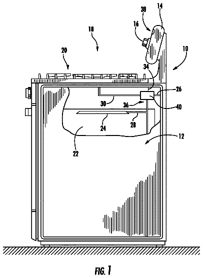
LED lamp with speaker
A light emitting diode (LED) lamp with at least one speaker is provided.
US 9,958,419 B2 · Assignee: FUJIFILM Corporation · Inventors: Irisawa; Kaku
Sheet 1 of 22 from the published document. All sheets in the USPTO PDF
It is desirable to more stably and efficiently transmit light in a housing of a light source unit. A light source unit 13 , which emits a laser beam L to a light guide part 40 , includes: a unit housing 13 b that includes a connector receiving portion 51 b detachably connected to a connector portion 51 a ; a light source 30 that is installed in the unit housing 13 b and outputs the laser beam L; a diffusion part 80 that diffuses the laser beam L output from the light source 30 ; a condensing lens system 81 that condenses the laser beam L diffused by the diffusion part 80 ; and an optical fiber 82 a that transmits the laser beam L, which is condensed by the condensing lens system 81 , to the connector receiving portion 51 b . The connector receiving portion 51 b optically connects the optical fiber 82 a to the light guide part 40.
Photoacoustic spectroscopy is a method that includes irradiating a subject with light having a predetermined wavelength (for example, the wavelength band of visible light, near infrared light, or middle infrared light) and detecting a photoacoustic wave, which is an elastic wave generated when a specific material contained in the subject absorbs the energy of this light, to measure the concentration or distribution of the specific material (for example, JP2010-12295A). The specific material contained in the subject is glucose, hemoglobin, or the like contained in blood when the subject is, for example, a human body. Further, a technique, which detects photoacoustic waves and generates a photoacoustic image on the basis of the detected signals, is called photoacoustic imaging (PAI) or photo-acoustic tomography (PAT). Since the intensity of a laser beam, which is applied to the subject, is
1 of 22 drawing sheets so far from the published document, cropped to the drawing. Every sheet is in the USPTO PDF.
What the patent claimed, word for word. All of it is now free to use.
The present invention relates to a light source unit that emits a laser beam and a photoacoustic measurement apparatus using the light source unit.
Photoacoustic spectroscopy is a method that includes irradiating a subject with light having a predetermined wavelength (for example, the wavelength band of visible light, near infrared light, or middle infrared light) and detecting a photoacoustic wave, which is an elastic wave generated when a specific material contained in the subject absorbs the energy of this light, to measure the concentration or distribution of the specific material (for example, JP2010-12295A). The specific material contained in the subject is glucose, hemoglobin, or the like contained in blood when the subject is, for example, a human body. Further, a technique, which detects photoacoustic waves and generates a photoacoustic image on the basis of the detected signals, is called photoacoustic imaging (PAI) or photo-acoustic tomography (PAT).
Since the intensity of a laser beam, which is applied to the subject, is significantly attenuated due to absorption or scattering while the laser beam is propagated through the subject, a laser beam having high light energy is generally used in the measurement (photoacoustic measurement) using the photoacoustic spectroscopy. As shown in, for example, FIG. 20 , a photoacoustic measurement apparatus 1 includes a probe 4 for photoacoustic measurement, a light source unit 3 that supplies a laser beam L to the probe 4 , and an acoustic signal processing unit 2 that processes signals of the photoacoustic waves detected by the probe 4 . Further, for convenience of use, the probe 4 and the acoustic signal processing unit 2 are detachably connected to each other by a first connector 5 a , and the probe 4 and the light source unit 3 are detachably connected to each other by a second connector 5 b . An acoustic detecting element array 4 a is provided in the probe 4 , and the acoustic detecting element array 4 a is connected to control means 2 a of the acoustic signal processing unit 2 by a control signal line 4 c . A laser beam L output from a light source 3 a is guided to an end of the probe 4 by an optical fiber 4 b , and a subject M is irradiated with the laser beam L.
Incidentally, when the probe and the light source unit are detachably connected to each other as described above, space transmission is frequently used without a light guide member such as an optical fiber as the transmission of a laser beam in a housing of the light source unit. The reason for this is that an optical fiber cannot withstand light energy and is broken when a laser beam is transmitted using an optical fiber in the housing. For example, the transmission of a laser beam L between the light source 3 a and the second connector 5 b in the light source unit 3 of FIG. 20 is performed by space transmission.
However, when space transmission is employed as the transmission of a laser beam in the housing as described above, the inside of the housing of the light source unit and a housing wall move in different manners with a temperature change and vibration. Accordingly, the incident position of a laser beam, which is incident on a connector receiving portion, is shifted. For this reason, there are problems in that the amount of energy to be transmitted may not be stable and transmission efficiency may be lowered. In this case, there may be a case in which transmission efficiency is lower than the efficiency of light transmission using the light guide member.
The invention has been made in consideration of the above-mentioned problems, and an object of the invention is to provide a light source unit that can more stably and efficiently transmit light in a housing of the light source unit and a photoacoustic measurement apparatus using the light source unit.
In order to solve the above-mentioned problems, a light source unit, which emits a laser beam to a light guide part of a probe, according to the invention includes a unit housing having a connector receiving portion detachably connected to a connector portion of the light guide part, a light source that is installed in the unit housing and outputs the laser beam, a diffusion part that diffuses the laser beam output from the light source, a condensing lens system that condenses the laser beam diffused by the diffusion part, and a light transmitting part that includes an optical fiber transmitting the laser beam, which is condensed by the condensing lens system, to the connector receiving portion. The connector receiving portion optically connects the optical fiber to the light guide part.
Meanwhile, a photoacoustic measurement apparatus according to the invention includes a probe that has a light guide part guiding a laser beam emitted toward a subject to generate a photoacoustic wave, and the light source unit.
Further, in the light source unit and the photoacoustic measurement apparatus according to the invention, the optical fiber may be a single fiber.
Further, when the optical fiber is a single fiber, the light transmitting part may have a light energy resistant structure at a light incident-side end portion of the optical fiber, the condensing lens system may condense the laser beam so that a minimum beam diameter D of the laser beam defined by the following expression 1 is d.sub.in/2 or more in a relationship between a diameter d.sub.in of a core of the optical fiber on a light incident side and the minimum beam diameter D, and a light incident-side end face of the core of the optical fiber may be disposed so that the laser beam is incident on the light incident-side end face of the core while the diameter of the laser beam is d.sub.in/2 or more. In this case, the light transmitting part may be an air gap-optical fiber cable having a covering member that covers the optical fiber so that a side surface of the optical fiber adjacent to an end face of the optical fiber is exposed to the outside.
D = A .Math. f .Math. tan ( ( ϕ 2 ) 2 + ( θ 2 ) 2 ) Expression 1
In Expression 1, A denotes a coefficient that is determined depending on the kind of the diffusion part, f denotes a focal length of the condensing lens system, φ denotes a spread angle of the laser beam when the laser beam is incident on the diffusion part, and θ denotes a diffusion angle of the diffusion part.
The “spread angle” means an angle where the diameter of a laser beam is increased with the propagation of the laser beam. Further, the “diffusion angle” of the diffusion part means a design diffusion angle, that is, an angle where the diameter of a laser beam as parallel light incident on and transmitted through the diffusion part is increased with the propagation of the laser beam. Meanwhile, the “spread angle” and the “diffusion angle” are represented by a total plane angle. When these angles are to be measured, it is preferable that a beam diameter be measured at about 10 points within a range of a propagation distance until a certain beam diameter is increased to double the beam diameter and the angles be obtained from the inclination of the change of the beam diameter at this time.
Furthermore, the “beam diameter” is set to the diameter of a circle which includes about 86.5% energy and of which the center is positioned on a beam center (generally, a position where the intensity of a beam is the maximum) in the energy profile of the laser beam L, that is, a so-called 1/e.sup.2 diameter. In this case, when it is difficult to obtain a beam center due to the irregular distribution of the intensity of a beam, or the like, circles in which energy is 86.5% in the vicinity of a position that is estimated as the beam center are exhaustively made and the diameter of a circle having the minimum area among these circles may be used as the beam diameter.
Alternatively, when the optical fiber is a single fiber, the condensing lens system may condense the laser beam so that a minimum beam diameter D of the laser beam defined by Expression 1 is in the range of d.sub.in/3 to 2d.sub.in/3 in a relationship between a diameter d.sub.in of a core of the optical fiber on a light incident side and the minimum beam diameter D, and a light incident-side end face of the core of the optical fiber may be disposed so that the laser beam is incident on the light incident-side end face of the core while the diameter of the laser beam is in the range of d.sub.in/3 to 2d.sub.in/3.
Further, in the light source unit and the photoacoustic measurement apparatus according to the invention, the diffusion part may be a lens diffuser in which small lenses are randomly disposed on a surface of a substrate.
Furthermore, in the light source unit and the photoacoustic measurement apparatus according to the invention, the diffusion part may make a top of the energy profile of the incident laser beam flat.
Moreover, in the light source unit and the photoacoustic measurement apparatus according to the invention, the diffusion part may be an engineered diffuser and the coefficient A may be 2.5.
Further, in the light source unit and the photoacoustic measurement apparatus according to the invention, the diffusion part may be a holographic diffuser and the coefficient A may be 2.4.
Furthermore, in the photoacoustic measurement apparatus according to the invention, the light guide part may be a bundle fiber, and a diameter d.sub.out of the core of the optical fiber on a light-emitting side and a bundle diameter B of the bundle fiber may satisfy the following expression 2. 0.8B≤d.sub.out≤1.2B Expression 2
Moreover, in the light source unit and the photoacoustic measurement apparatus according to the invention, the connector receiving portion may hold the optical fiber so that a direction of a first optical axis of the optical fiber on a light-emitting side has an inclination.
In addition, when the direction of the first optical axis has an inclination, an insertion passage of the connector receiving portion into which an insertion portion of the connector portion is inserted may have a guide structure guiding the insertion portion with the insertion of the insertion portion so that a second optical axis of the light guide part on a light incident side corresponds to the first optical axis. In this case, in the guide structure, an opening width of the insertion passage may be larger than the width of an inner portion of the insertion passage and an inner wall surface of the insertion passage may be curved from an opening side toward an inner portion side. Further, the inner wall surface of the insertion passage may be provided with rollers.
The light source unit and the photoacoustic measurement apparatus according to the invention transmit light to the connector receiving portion in the housing by using the optical fiber. Accordingly, even though the inside of the housing and the housing wall move in different manners with a temperature change and vibration, it is possible to prevent the incident position of light, which is incident on the connector receiving portion, from being shifted. In addition, the light source unit and the photoacoustic measurement apparatus according to the invention increase the distribution of a propagation angle of light flux, which is included in a laser beam, by allowing the laser beam to pass through the diffuser once, and control a beam diameter of the laser beam incident on the optical fiber, by using the focal length of the condensing lens system. Accordingly, when condensing a laser beam by the condensing lens system and allowing the laser beam to be incident on the optical fiber, the light source unit and the photoacoustic measurement apparatus can prevent the laser beam from being excessively narrowed. Therefore, it is possible to prevent damage to the optical fiber that is caused when local light energy exceeds the damage threshold energy of the optical fiber. As a result, it is possible to more stably and efficiently transmit light in the housing of the light source unit.
Moreover, while a laser beam is transmitted through the optical fiber, the energy profile of the laser beam is made uniform. Accordingly, an effect of uniformly transmitting light to the light guide part of the probe is also obtained.
FIG. 1 is a schematic view showing the configuration of a photoacoustic measurement apparatus of a first embodiment.
FIG. 2 is a block diagram showing the internal configuration of the photoacoustic measurement apparatus of the first embodiment.
FIG. 3 is a schematic view showing the configuration of the inside of a unit housing.
FIGS. 4A and 4B are schematic views showing examples of the configuration of an optical system that includes a diffusion part, a condensing lens system, and an optical fiber cable.
FIG. 5 is a schematic cross-sectional view showing an embodiment of an optical fiber that includes a light energy resistant structure at an end portion thereof.
FIG. 6 is a schematic cross-sectional view showing another embodiment of the optical fiber that includes the light energy resistant structure at the end portion thereof.
FIG. 7 is a schematic cross-sectional view showing another embodiment of the optical fiber that includes the light energy resistant structure at the end portion thereof.
FIG. 8 is a view showing the energy profile of a beam at a lens focus position when a laser beam diffused by a diffuser is condensed by the condensing lens system.
FIG. 9 is a view showing the energy profile of a beam at the lens focus position when the diffuser is not used and the laser beam is condensed by the condensing lens system.
FIG. 10A is a view showing the energy profile of a laser beam that is condensed by a lens after the top of the energy profile of the laser beam is made flat by an engineered diffuser, and FIG. 10B is a view showing the energy profile of a laser beam that is condensed by a lens after the laser beam is diffused by a holographic diffuser.
FIG. 11 is a graph showing a relationship between the optical characteristics of a lens diffuser and the condensing lens system and the minimum beam diameter.
FIG. 12 is a graph showing a correlationship between the diameter of a light condensing range and the minimum beam diameter when laser beam flux in which an angle between a travelling direction and an optical axis of the condensing lens system has a distribution is condensed by the condensing lens system (when the engineered diffuser is used).
FIG. 13 is a graph showing a correlationship between the diameter of a light condensing range and the minimum beam diameter when laser beam flux in which an angle between a travelling direction and an optical axis of the condensing lens system has a distribution is condensed on the condensing lens system (when the holographic diffuser is used).
FIG. 14 is a graph showing a relationship between a beam diameter at the lens focus position and the damage threshold energy of a core of a general optical fiber cable, as a result in experiments in which conditions of the diffuser and the condensing lens system are changed.
FIG. 15 is a graph showing a relationship between a beam diameter at the lens focus position and the damage threshold energy of a core of an air gap-optical fiber cable, as a result in experiments in which conditions of the diffuser and the condensing lens system are changed.
FIGS. 16A and 16B are schematic views showing another example of the structure of a connector.
FIGS. 17A, 17B, and 17C are schematic views showing another example of the structure of the connector.
FIG. 18 is a schematic view showing another example of the structure of the connector.
FIG. 19 is a block diagram showing the internal configuration of a photoacoustic measurement apparatus of a second embodiment.
FIG. 20 is a schematic view showing the configuration of a photoacoustic measurement apparatus in the related art.
Embodiments of the invention will be described below with reference to the drawings, but the invention is not limited thereto. Meanwhile, for the facilitation of visual recognition, the scale or the like of each component in the drawings may be appropriately different from the scale of an actual component.
[First Embodiment]
FIG. 1 is a schematic view showing the configuration of a photoacoustic measurement apparatus of a first embodiment, and FIG. 2 is a block diagram showing the internal configuration of the photoacoustic measurement apparatus of the first embodiment. Further, FIG. 3 is a schematic view showing the configuration of a part of the inside of a unit housing. Meanwhile, in this embodiment, the photoacoustic measurement apparatus is a photoacoustic image forming apparatus that forms photoacoustic images on the basis of photoacoustic signals.
As shown in FIG. 1 , the photoacoustic image forming apparatus 10 of this embodiment includes a probe 11 , an ultrasonic unit 12 , a laser unit 13 , and a personal computer (PC) 17 . Further, a subject M is irradiated with a beam L, which is emitted from the laser unit 13 , through the probe 11 and a photoacoustic wave, which is caused by the irradiation with the beam, is detected by the probe 11 .
<Probe>
As shown in FIGS. 1 and 2 , the probe 11 is mainly divided into a probe main body 11 a (a portion on which inherent functions of the probe are concentrated) and a cable portion 11 b . Further, the probe main body 11 a mainly includes light guide plates 41 , an acoustic detector 42 , and a housing 45 that houses the light guide plates 41 and the acoustic detector 42 . Meanwhile, an optical fiber 40 and an acoustic signal line 44 are mainly inserted into the cable portion 11 b . The probe 11 and the ultrasonic unit 12 are detachably connected to each other by a connector 50 , and the probe 11 and the laser unit 13 are detachably connected to each other by a connector 51 .
The optical fiber 40 is optically connected to the laser unit 13 , which outputs a laser beam L, through the connector 51 , and guides the laser beam L to the light guide plates 41 . The optical fiber 40 corresponds to a light guide part of the invention. The optical fiber 40 is not particularly limited, and a known fiber, such as a quartz fiber, can be used as the optical fiber 40 . A single fiber or a bundle fiber may be used as the optical fiber 40 , but a bundle fiber is more preferable. Further, when the optical fiber 40 is a bundle fiber, it is preferable that the bundle fiber be a fused bundle fiber of which a light incident-side end portion is fused. In the fused bundle fiber, clads of optical fibers are fused to one another so that the optical fibers are bundled in a hexagonal honeycomb shape. Accordingly, a clearance between the optical fibers is reduced in comparison with bundling using an adhesive. For this reason, there is an advantage of increasing an area, which is occupied by the core, per unit area. Furthermore, since a material, which is weak against light energy, does not appear at the light incident-side end portion of the bundle fiber, there also is an advantage of improving durability against light energy.
The light guide plate 41 is a plate that is obtained by performing special processing on the surface of, for example, an acrylic plate or a quartz plate and uniformly emits light, which has been incident on one end face thereof, from the other end face thereof. For example, in this embodiment, two light guide plates 41 are disposed so as to face each other with the acoustic detector 42 interposed therebetween. The optical fiber 40 is optically connected to the light guide plates 41 . For example, portions of the light guide plates 41 connected to the optical fiber 40 are formed in a tapered shape as shown in FIG. 1 . Accordingly, an area to be irradiated with light can be widened.
The acoustic detector 42 detects an acoustic wave from a subject, and generates electric signals (acoustic signals) corresponding to the intensity of the detected acoustic wave. Meanwhile, in this specification, the “acoustic wave” means a wave that includes an ultrasonic wave and a photoacoustic wave. Here, the “ultrasonic wave” means an elastic wave, which is generated in a subject by the vibration of an acoustic wave generator such as a piezoelectric element, and the reflected wave thereof, and the “photoacoustic wave” means an elastic wave that is generated in a subject due to a photo-acoustic effect caused by the irradiation with light. The acoustic detector 42 includes, for example, a backing material, an acoustic detecting element array, a control circuit for the acoustic detecting element array, an acoustic matching layer, and an acoustic lens. The acoustic detecting element array is an array in which a plurality of acoustic detecting elements are one-dimensionally or two-dimensionally arrayed, and converts an actually detected acoustic wave into an electric signal. The acoustic detecting element is a piezoelectric element that is formed of a film made of a polymer, such as piezoelectric ceramics or polyvinylidene fluoride (PVDF).
The acoustic signal line 44 is an electrical signal line that transmits acoustic signals generated by the acoustic detector 42 to the ultrasonic unit 12 or transmits signals transmitted from the ultrasonic unit 12 to the control circuit for the acoustic detecting element array.
<Ultrasonic Unit>
The ultrasonic unit 12 receives photoacoustic signals, which are transmitted from the probe 11 , through the connector 50 , and forms a photoacoustic image on the basis of the photoacoustic signals. The ultrasonic unit 12 and the laser unit 13 are connected to each other by a control signal line 62 . The details of the ultrasonic unit 12 will be described below.
The connector 50 is a connecting member that electrically connects the acoustic signal line 44 to a receiving circuit 21 of the ultrasonic unit 12 . For example, a known multi-core connector can be used as this connector. The connector 50 includes a plug 50 a and a receptacle 50 b that has a structure corresponding to the plug 50 a and is detachably connected to the plug 50 a.
The control signal line 62 is a signal line that connects control means 60 of the ultrasonic unit 12 to control means 61 of the laser unit 13 , and is, for example, an electrical signal line. The ultrasonic unit 12 and the laser unit 13 can communicate with each other by transmitting and receiving a control signal through the control signal line 62 . In this specification, the meaning of “transmitting and receiving” a control signal includes that a control signal is unidirectionally transmitted from one of the ultrasonic unit 12 and the laser unit 13 to the other thereof and both the units bidirectionally transmit or receive a control signal.
A control signal is, for example, a trigger signal that synchronizes an output timing of a laser beam with photoacoustic detection timing. The trigger signal may be a signal that is transmitted to the ultrasonic unit 12 by the laser unit 13 , and may be a signal indicating the output of a laser beam (that is, a trigger signal in the setting where the laser unit is a superordinate). Alternatively, the trigger signal may be a signal that is transmitted to the laser unit 13 by the ultrasonic unit 12 , and may be a signal instructing the output of a laser beam to be prepared or instructing a laser beam to be output (that is, a trigger signal in the setting where the ultrasonic unit is a superordinate).
<Laser Unit>
The laser unit 13 includes an oscillator 30 that oscillates a laser beam L, a diffusion part 80 , a condensing lens system 81 , an optical fiber cable 82 , and a unit housing 13 b that houses the oscillator 30 , the diffusion part 80 , the condensing lens system 81 , and the optical fiber cable 82 . The laser unit 13 emits a laser beam L as light with which the subject M is irradiated. The laser unit 13 corresponds to a light source unit of the invention. For example, the laser unit 13 is adapted to receive a trigger signal, which is transmitted from the control means 60 of the ultrasonic unit 12 , and to emit a laser beam L. The laser beams L, which is emitted from the laser unit 13 , is guided to the light guide plates 41 of the probe 11 by the light guide part such as the optical fiber 40 . Casters 13 a are provided on the bottom of the laser unit 13 so that the laser unit 13 can be easily moved. Further, the unit housing 13 b includes a receptacle 51 b that forms the connector 51 .
In this embodiment, an optical system provided in the laser unit 13 is formed so that a laser beam L is incident on an end portion of the optical fiber 40 connected by the connector 51 . That is, the laser beam L, which is incident on the diffusion part 80 after being output from the oscillator 30 , is incident on a light incident-side end portion 82 e of the optical fiber cable 82 through the condensing lens system 81 . After that, the laser beam L, which is transmitted by using the optical fiber cable 82 , is emitted to the optical fiber 40 of the probe 11 at the connector 51 . The optical system will be described in detail below.
The structure of the oscillator 30 is not particularly limited. However, as shown in FIG. 3 , the oscillator 30 includes a laser rod 70 , an excitation lamp 71 , a laser chamber 72 , an output mirror 73 , a total reflection mirror 74 , a Q-switch 32 , and a housing 78 that houses the laser rod 70 , the excitation lamp 71 , the laser chamber 72 , the output mirror 73 , the total reflection mirror 74 , and the Q-switch 32 . In this embodiment, the oscillator 30 corresponds to a light source of the invention. The laser rod 70 is a solid element including an active solid medium, and it is preferable that the laser rod 70 be alexandrite. The excitation lamp 71 is a light source that supplies energy for allowing the laser rod 70 to induce and emit light. For example, a rod-like flash lamp, which is filled with Xe gas, can be employed as the excitation lamp 71 . The laser chamber 72 includes the laser rod 70 and the excitation lamp 71 , and is a member for condensing light, which is emitted from the excitation lamp 71 , on the laser rod 70 . The laser chamber 72 is formed so that a coolant flowing in from a pipe 79 a passes through the laser chamber 72 and flows out of a pipe 79 b . The Q-switch 32 is disposed between the laser rod 70 and the total reflection mirror 74 on an optical axis of a beam Lo that is induced and emitted. The Q-switch 32 includes, for example, a λ/4 plate 75 , a Pockels cell 76 , and a polarizer 77 . The housing 78 includes an opening 78 a which is formed at the side wall of a portion thereof facing the output mirror 73 and through which the laser beam Lo is emitted. Meanwhile, the oscillator 30 may include other optical elements as necessary.
For example, the oscillator 30 is a Q-switch alexandrite laser in this embodiment. It is preferable that the oscillator 30 output pulse light having a pulse width of 1 to 150 nsec as a laser beam L. In this case, the pulse width of the laser beam L is controlled by, for example, the Q-switch. The wavelength of the laser beam is appropriately determined depending on the optical absorption property of a material present in a subject that is an object to be measured. For example, when an object to be measured is hemoglobin present in a living body (that is, when a blood vessel is imaged), it is preferable that the wavelength of a laser beam generally be a wavelength belonging to a near-infrared wavelength region. The near-infrared wavelength region means a wavelength region of about 700 to 850 nm. However, it is natural that the wavelength of a laser beam is not limited thereto. Further, laser beams L may have a short wavelength, and may have a plurality of wavelengths (for example, 750 nm and 800 nm). Furthermore, when the laser beams L have a plurality of wavelengths, the subject M may be simultaneously irradiated with the beams having these wavelengths and may be irradiated with the beams while the beams are alternately switched. The oscillator 30 may be a YAG-SHG-OPO laser or a Ti-Sapphire laser, which can output a laser beam corresponding to a near-infrared wavelength region likewise, other than the alexandrite laser.
The diffusion part 80 increases the diameter of the laser beam L by diffusing the laser beam L that is output from the oscillator 30 . That is, the diffusion part 80 functions to increase the distribution of a propagation angle of light flux, which is included in the laser beam L, by allowing the laser beam L to pass through the diffusion part once. Accordingly, since the light-emitting surface of the diffusion part 80 serves as a secondary light source of the laser beam L, it is possible to prevent the laser beam L from being excessively narrowed when the laser beam L is condensed by the condensing lens system 81 . The diffusion part 80 is disposed at a position where the laser beam L output from the oscillator 30 is received. Meanwhile, other optical elements can be provided between the oscillator 30 and the diffusion part 80 as necessary.
It is preferable that the diffusion part 80 be a diffuser, and it is particularly preferable that the diffusion part 80 be a lens diffuser. Further, a diffusion angle of the diffusion part 80 is preferably in the range of 0.2 to 5.0° and more preferably in the range of 0.4 to 3.0°. The reason for this is that diffusion efficiency is high. For example, a holographic diffuser, which is a lens diffuser in which small convex lenses are randomly disposed on the surface (for example, one surface) of a substrate, can be employed as the diffusion part 80 . For example, a holographic diffuser manufactured by Edmunds (Model No.: 48513-L, material: quartz, diffusion angle: 0.5°, and transmission efficiency: 93%) can be used as this holographic diffuser.
Furthermore, it is preferable that the diffusion part 80 be a homogenizer. The homogenizer is an optical element that makes the top of the energy profile (energy distribution) of the laser beam L, which is incident from the upstream side of the optical system, flat and diffuses the laser beam L. The laser beam L of which the top has been made flat is guided to the condensing lens system 81 , and is incident on the light incident-side end portion 82 e of the optical fiber cable 82 while having a flat-top energy profile. In other words, “making the top of the energy profile flat” is to form a laser beam, which is incident on the homogenizer, into a laser beam of which the central portion has a flat-top energy profile. In this specification, “flat-top” means a state in which, when a concentric circle in which the diameter of the energy profile of the laser beam emitted from the homogenizer is 80% of the beam diameter is taken and a standard deviation of the energy of each point in this concentric circle is within 25% of average energy in this concentric circle. In general, the structure of the homogenizer is designed so that light is made completely flat-top at infinity (that is, the standard deviation is substantially equal to 0). However, in the invention, an energy profile, when a laser beam is incident on the light incident-side end portion 82 e of the optical fiber cable 82 , does not necessarily need to be in a completely flat-top state, and is sufficient to be in a flat-top state substantially corresponding to the above-mentioned range. Since a local increase in the intensity of light is further prevented when the top of the energy profile of the laser beam L is made flat, damage to the optical fiber cable 82 is also further suppressed.
The homogenizer may be formed of a single optical element, and may be formed of a combination of a plurality of optical elements. When the homogenizer is formed of a single optical element, it is preferable that a lens diffuser in which small concave lenses or the like are randomly disposed on the surface (for example, one surface) of a substrate be used as the homogenizer. For example, an engineered diffuser manufactured by RPC Photonics, Inc. (Model No.: EDC-2.0-A and diffusion angle: 2.0°) can be used as this lens diffuser. It is possible to substantially arbitrarily change the energy profile and the shape of the laser beam L by using these elements. When the homogenizer is formed of a single optical element as described above, the configuration of the diffusion part can be simplified.
Meanwhile, even when the homogenizer is formed of a plurality of optical elements, an effect of adjusting a beam diameter, which is obtained after the condensation of light, to a predetermined value by the control of the distribution of an angle of a beam as in the diffuser only has to be obtained and, for example, the following configuration can be used. FIGS. 4A and 4B are schematic views showing examples of the configuration of an optical system of the diffusion part 80 . The homogenizer as the diffusion part 80 may have a configuration in which, for example, a microlens array 85 and a microlens array 86 are disposed as shown in FIG. 4A . Further, the homogenizer can be formed of a flat-top laser beam shaper 92 in which, for example, an aspherical lens for correcting the energy profile of a beam or the distribution of an angle of a beam is assembled as shown in FIG. 4B .
The condensing lens system 81 guides the laser beam L, which has passed through the diffusion part 80 , to the light incident-side end portion 82 e of the optical fiber cable 82 . The focal length of the condensing lens system 81 (a distance between a focal point and a main point on the optical fiber cable 82 ) is preferably in the range of 10 to 100 mm and more preferably in the range of 15 to 50 mm. The reason for this is that the size of the optical system can be reduced and a focal length is matched to the numerical aperture NA (about 0.22 at a maximum) of a general optical fiber of which a core is made of quartz and a clad is made of fluorine-doped quartz. Further, the condensing lens system 81 may be a coupled lens that includes a plurality of lenses. When the condensing lens system 81 is a coupled lens, the focal length of the condensing lens system 81 means the composite focal length of the coupled lens.
A distance between the diffusion part 80 and the condensing lens system 81 is appropriately adjusted so that the laser beam L diffused by the diffusion part 80 is efficiently coupled to the condensing lens system 81 . In this case, it is preferable that the diffusion part 80 be disposed on the upstream side of the condensing lens system 81 in the optical system and within a range corresponding to three times a focal length from the center of the condensing lens system 81 .
The optical fiber cable 82 transmits the laser beam L, which has been condensed by the condensing lens system 81 , to the receptacle 51 b to be described below. The optical fiber cable 82 corresponds to a light transmitting part of the invention. Meanwhile, the light transmitting part of the invention does not need to be an optical fiber cable that includes an optical fiber and a covering member for covering the optical fiber, and may be formed of only an optical fiber. The optical fiber cable 82 may be fixed to the receptacle 51 b , and may be detachably fixed to the receptacle 51 b . As long as the optical fiber cable 82 can be fixed to the receptacle 51 b at least when a laser beam L is emitted from the optical fiber cable 82 , an object of the invention can be achieved. The optical fiber cable 82 includes, for example, an optical fiber that includes a core and a clad, and covering members such as a ferrule and a sheath covering the periphery of the optical fiber. The optical fiber cable 82 may be a single fiber and may be a bundle fiber. However, since a coupling loss is large when the optical fiber cable 82 is a bundle fiber, it is preferable that the optical fiber cable 82 be a single fiber. When the optical fiber cable 82 is a single fiber, the diameter of a core of an optical fiber of the optical fiber cable is preferably in the range of 100 to 2000 μm and more preferably in the range of 200 to 1200 μm. The optical fiber of the optical fiber cable 82 is not particularly limited, but it is preferable that the optical fiber of the optical fiber cable 82 be a quartz fiber. An SMA-type optical fiber manufactured by Thorlabs Inc. can be used as the optical fiber cable 82 .
Further, it is preferable that the optical fiber cable 82 include a light energy resistant structure at a light incident-side end portion thereof. In this specification, the “light energy resistant structure” means a structure that suppresses damage caused by the energy of a laser beam. Specifically, a so-called air gap-optical fiber cable including an air gap 88 can be used as the optical fiber cable 82 including the light energy resistant structure. For example, an optical fiber cable 82 ( FIG. 5 ) that includes an optical fiber 82 a of which the damage threshold energy density of a clad 84 b (the intensity of energy per unit area when the structure of the clad 84 b starts to be damaged by the energy of a laser beam) is substantially equal to the damage threshold energy density of a core 84 a (for example, an optical fiber of which a core is made of quartz and a clad is made of fluorine-doped quartz, or the like) and a ferrule 87 a that covers the optical fiber 82 a so that the side surface of the clad 84 b near an end face of the clad 84 b is exposed to the outside; an optical fiber cable that includes an optical fiber of which a clad near an end face is removed and the side surface of a core near the end face is exposed to the outside, and a ferrule that covers the optical fiber so that the side surface of the core near the end face is exposed to the outside; and an optical fiber cable 82 ( FIG. 6 ) that includes an optical fiber 82 a having a structure (end cap structure) in which a member 88 a made of a material (quartz or the like) of which the damage threshold energy density is substantially equal to the damage threshold energy density of a core 84 a is connected to an end portion and a ferrule 87 a that covers the optical fiber 82 a so that the side surface of the member 88 a is exposed to the outside can be used as the air gap-optical fiber cable.
When the optical fiber cable 82 is an air gap-optical fiber cable having a structure in which the side surface of the core 84 a or the clad 84 b near the end face thereof is exposed to the outside, it is preferable that an exposed range of the core 84 a or the clad 84 b be set in the range of 1 to 3 mm from the end of the optical fiber cable. The reason why the exposed range of the core 84 a or the clad 84 b is set to 1 mm or more is that a distance between a material provided around the core 84 a or the clad 84 b and the end of the optical fiber cable 82 needs to be set so that the energy density of light emitted to the outside of the core is reduced and energy absorbed by the material provided around the core 84 a or the clad 84 b becomes smaller than the damage threshold energy of the material. Further, the reason why the exposed range of the core 84 a or the clad 84 b is set to 3 mm or less is to prevent the occurrence of damage to the optical fiber cable that is caused by bending and folding when a light incident surface of the end face of the optical fiber cable 82 is polished. The optical fiber 82 a of the optical fiber cable 82 is not particularly limited, but it is preferable that the optical fiber 82 a be a quartz fiber. It is possible to produce the air gap-optical fiber cable by, for example, polishing the end faces of a quartz fiber and a commercially available air gap-ferrule after inserting the quartz fiber into the commercially available air gap-ferrule and fixing the quartz fiber by adhesion.
The description continues in the full USPTO document.
About 7,110 words. The USPTO PDF has it with every drawing.
Fees are due 3.5, 7.5 and 11.5 years after grant. This patent expired on May 1, 2026, so the fee marked "not paid" was the one that went unpaid.
LIGHT SOURCE UNIT AND PHOTOACOUSTIC MEASUREMENT APPARATUS USING THE SAME
Filed Feb 2015 · published Jun 2015Light source unit and photoacoustic measurement apparatus using the same
Filed Feb 2015 · granted May 2018Earlier publications, parents and continuations. None of them can still be enforced, or this patent would not be listed.
Prior art cited by the examiner or applicant. Useful when you check your own idea for novelty.
Everything on this page comes from the documents linked above.