Lapsed, fee not paid2 drawings
Industrial Equipment · US 9,958,021 B2
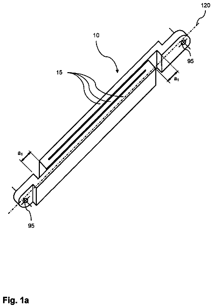
Brake pad retainer for a disc brake
A brake pad retainer is provided for a disc brake for a commercial vehicle.
US 9,958,026 B2 · Assignee: CANON KABUSHIKI KAISHA · Inventors: Endo; Rie et al.
Sheet 1 of 25 from the published document. All sheets in the USPTO PDF
A damping structure includes a first frame on which a driving portion is mounted, a second frame provided at a position facing the first frame in a state being connected with the first frame, a projecting portion provided projectively from one frame toward the other frame of the first and second frames, and a damping member compressively held between the projecting portion and the other frame. The damping member has rigidity lower than rigidities of the first and second frames and of the projecting portion and has a loss factor, measured by a mechanical impedance method in the state being compressed between the projecting portion and the other frame, of 0.05 or more.
1 of 25 drawing sheets so far from the published document, cropped to the drawing. Every sheet is in the USPTO PDF.
What the patent claimed, word for word. All of it is now free to use.
BACKGROUND OF THE INVENTION Field of the Invention
The present invention relates to a damping structure capable of reducing vibration transmitted from an exciter such as a motor to a frame. Description of the Related Art
Lately, frames, such as a casing, are formed of a thin metal plate or the like to lighten a weight of various products such as office equipment (e.g., a printer), home appliances (e.g., a refrigerator), automobiles and construction materials. Such frames may radiate sound when vibration generated by an exciter, such as a motor, is transmitted to the frames. Then, there is a demand to reduce the vibration of a vibrated member, such as the frame, to which the vibration is transmitted from the exciter. For instance, a method of reducing the vibration of the vibrated member by pasting a damping member on a surface of a part or a whole of the vibrated member is conventionally known as disclosed in Japanese Unexamined Patent Application Publication No. 2006-168652, for example. Still further, as another method of reducing the vibration of the vibrated member, there is known a method of pasting a damping steel plate in which a damping member is interposed and welded between two metal thin plates on a surface of the vibrated member.
Japanese Unexamined Patent Application Publication No. 9-125558 also proposes a metal thin plate structure using a metal thin plate as a panel and configured such that an echo damping sheet is interposed between and in contact with a beam reinforcing the metal thin plate and the metal thin plate to reduce an echo sound generated when the metal thin plates are knocked.
In the construction field, there are many apparatuses reducing vibration by absorbing vibration energy of a vibration whose amplitude is large and whose frequency is low, such as vibrations being generated by earthquake or the like. For instance, Japanese Unexamined Patent Application Publication No. 2007-278411 proposes a damper in which inner and outer cylindrical rigid members are attached to two relatively movable different objects, respectively. These inner and outer cylindrical rigid members are connected in a body through a viscoelastic energy absorbing member. Specifically, both members are bonded in a body by vulcanizing a non-vulcanized rubber while filling between the inner and outer cylindrical rigid members or by foaming a resin material filling between them. Then, vibration generated between the two members is reduced by the viscoelastic energy absorbing member interposed between these two members.
However, the methods of pasting the damping member and the damping steel plate to the vibrated member have a problem that a number of components increases because these method require a large amount of damping members. Still further, because the damping steel plate is hard to work, i.e., to bend or to draw, it is difficult to install the steel plate in a case when a pasting position is limited.
The metal thin plate structure disclosed in Japanese Unexamined Patent Application Publication No. 9-125558 discloses a beam installed between two sides of one thin metal plate (frame). Because this structure requires a wide area to install the beam, a position where the beam can be installed is limited and it becomes hard to install the beam if many components are disposed on the metal thin plate. Still further, because the wider the area of the thin metal plate, the more a large amount of echo sound reducing sheet is required, becoming costly.
The damper described in Japanese Unexamined Patent Application Publication No. 2007-278411 has a large vibration reducing effect on vibrations whose amplitude is large and whose frequency is low, such as earthquake. However, the viscoelastic energy absorbing member is considered to hardly distort and the vibration reducing effect is small to mechanical vibration whose amplitude is small and whose frequency is high as compared to earthquake. Still further, it takes time to manufacture the damper because the both members are bonded in a body by vulcanizing the non-vulcanized rubber while filling between the inner and outer cylindrical rigid members or by foaming a resin material while filling between them. For instance, it is conceivable to fill rubber between the both members by bringing both members, manufactured by a metalworking factory, to a mill for material such as rubber. In this case, it takes more time to manufacturing, as compared to a case of manufacturing both members and the viscoelastic energy absorbing member separately and combining them in an assembly plant. In particular, it is hard to manufacture the damper in a state in which the inner and outer cylindrical rigid members are assembled with an object whose vibration is to be reduced or in a case when these both members are formed integrally with the object.
The present invention provides a damping structure capable of damping a vibration of a frame with a simple configuration. According to an aspect of the present invention, a damping structure includes a first frame on which a driving portion is mounted, a second frame provided at a position facing the first frame in a state being connected with the first frame, a projecting portion provided projectively from one frame toward the other frame of the first and second frames, and a damping member compressively held between the projecting portion and the other frame. The damping member has rigidity lower than rigidities of the first and second frames and of the projecting portion and has a loss factor, measured by a mechanical impedance method in the state being compressed between the projecting portion and the other frame, of 0.05 or more.
Further features of the present invention will become apparent from the following description of exemplary embodiments with reference to the attached drawings.
FIG. 1 is a schematic section view illustrating a structure of an image forming apparatus to which a damping structure is applicable.
FIG. 2 is a section view illustrating a configuration of a drive unit seen from above.
FIG. 3 is a section view schematically illustrating a drive unit of a first embodiment.
FIG. 4A is a perspective view illustrating a damping pin including a press member.
FIG. 4B is a perspective view illustrating a damping pin including no press member.
FIG. 5A is a section view schematically illustrating a configuration of an experimental simplified drive unit composed of only a frame.
FIG. 5B illustrates a configuration of the experimental simplified drive unit in which a damping member is provided over an entire surface.
FIG. 5C illustrates a configuration of the experimental simplified drive unit in which only a pin member is provided.
FIG. 5D illustrates a configuration of the experimental simplified drive unit in which the damping pin is provided.
FIG. 6A is a graph indicating experimental results in terms of sound pressure levels of radiated sounds of the drive unit of the first embodiment and comparative examples.
FIG. 6B is a graph indicating overall values of the sound pressure levels shown in FIG. 6A .
FIG. 7A is a graph indicating experimental results in terms of sound pressure levels of radiated sounds in a case when the frames are coupled only by the pin member.
FIG. 7B is a graph indicating overall values of the sound pressure levels shown in FIG. 7A .
FIG. 8A is a graph indicating experimental results in terms of overall values of sound pressure levels of radiated sounds in a case when a compression amount of the damping member is varied.
FIG. 8B is a graph indicating experimental results in terms of overall values of vibration levels in the case when the compression amount of the damping member is varied.
FIG. 9A is a graph indicating experimental results in terms of sound pressure levels of radiated sounds in cases when the damping member and a vibration-proof member are used.
FIG. 9B is a graph indicating overall values of vibration levels shown in FIG. 9A .
FIG. 9C is a graph indicating experimental results in terms of overall values of vibration levels in cases when the damping member and a vibration-proof member are used.
FIG. 10 is a graph indicating sound pressure levels of radiated sounds and vibration levels per hardness when damping members and vibration-proof members are used.
FIG. 11A is a graph indicating experimental results in terms of sound pressure levels of radiated sounds when the damping pin and spring pin are used.
FIG. 11B is a graph indicating overall values of the vibration levels shown in FIG. 11A .
FIG. 11C is a graph indicating experimental results in terms of overall values of vibration levels when the damping pin and spring pin are used.
FIG. 12A is a chart indicating positions where the damping pins are disposed in the experiments when a number of the damping pins is varied.
FIG. 12B is a graph indicating sound pressure levels of radiated sounds.
FIG. 12C is a graph indicating overall values of the sound pressure levels shown in FIG. 12B .
FIG. 13 is a section view schematically illustrating a drive unit of a second embodiment.
FIG. 14 is a section view schematically illustrating a drive unit of a third embodiment.
FIG. 15 is a section view schematically illustrating a drive unit of a fourth embodiment.
FIG. 16 is a section view schematically illustrating a drive unit of a fifth embodiment.
FIG. 17 is a section view schematically illustrating a drive unit of a sixth embodiment.
FIG. 18 is a section view schematically illustrating a drive unit of a seventh embodiment.
FIG. 19 is a section view schematically illustrating a drive unit of an eighth embodiment.
FIG. 20 is a section view illustrating a damping pin.
FIG. 21A is an enlarged perspective view illustrating a connecting portion of the damping pin and the frame.
FIG. 21B is an enlarged perspective view illustrating another connecting portion of the damping pin and the frame.
FIG. 22 is a graph indicating experimental results of the drive unit of the eighth embodiment and comparative examples.
FIG. 23A is a perspective view schematically illustrating a drive unit of a ninth embodiment.
FIG. 23B is a section view of the drive unit shown in FIG. 23A .
FIG. 24A is a perspective view schematically illustrating a drive unit of a tenth embodiment.
FIG. 24B is a section view of the drive unit shown in FIG. 24A .
FIG. 25 is a section view schematically illustrating a drive unit of an eleventh embodiment. DESCRIPTION OF THE EMBODIMENTS First Embodiment
Embodiments of the present invention will be described below in detail with reference to the drawings. At first, an image forming apparatus to which a damping structure of the invention is applicable will be described with reference to FIG. 1 . The image forming apparatus shown in FIG. 1 is a tandem type direction transfer type full-color printer in which image forming portions PY, PM, PC, and PK are arrayed vertically along a transfer member conveying belt 5 .
In the image forming portion PY, a yellow toner image is formed on a photosensitive drum 1 Y and is transferred to a transfer member S, e.g., a recoding sheet, an OHP sheet, a sheet material such as cloth, to be borne and conveyed by the transfer member conveying belt 5 . In the image forming portion PM, a magenta toner image is formed on a photosensitive drum 1 M and is transferred to the transfer member S to be borne and conveyed by the transfer member conveying belt 5 . In the image forming portions PM and PK, cyan and black toner images are formed respectively on the phase differences 1 C and 1 K and are transferred to the transfer member S to be borne and conveyed by the transfer member conveying belt 5 . The transfer member S on which the four color toner images have been transferred is separated curvedly from the transfer member conveying belt 5 and is sent to a fixing unit 14 . The transfer member S undergoes heat and pressure in the fixing unit 14 to fix the toner image on a surface thereof. Then, the transfer member S is discharged out of an apparatus body.
The image forming portions PY, PM, PC and PK are configured in the same manner except that colors of toners used in developing units 4 Y, 4 M, 4 C, and 4 K are different as yellow, magenta, cyan, and black. Then, the yellow image forming portion PY will be typically described below and the other image forming portions PM, PC, and PK will be described by replacing Y at the end of the reference symbol PY with M, C, and K.
The image forming portion PY includes a charging roller 2 Y (primary charger), an exposure unit 3 Y, a developing unit 4 Y, and a transfer roller 12 Y around the photosensitive drum 1 Y, i.e., an image bearing member. The photosensitive drum 1 Y includes a photosensitive layer formed around an outer circumferential surface thereof and is rotated clockwise in FIG. 1 with a predetermined process speed.
The charging roller 2 Y electrifies the photosensitive drum 1 Y with a homogeneous negative dark potential. The exposure unit 3 Y scans a laser beam, in which scan line image data developing color separation image of each color, is ON-OFF modulated by a rotary mirror to form an electrostatic latent image on the surface of the photosensitive drum 1 Y. The developing unit 4 Y supplies the toner to the photosensitive drum 1 Y to develop the electrostatic latent image as a toner image.
The transfer roller 12 Y is in pressure contact with the transfer member conveying belt 5 to forma transfer portion of the toner image between the photosensitive drum 1 Y and the transfer member conveying belt 5 . Because a DC voltage of an opposite polarity from a charging polarity of the toner is applied to the transfer roller 12 Y, the toner image borne on the photosensitive drum 1 Y is transferred to the transfer member S on the transfer member conveying belt 5 . So-called transfer residual toner left while being borne on the photosensitive drum 1 Y after the transfer is removed by a drum cleaning unit not shown.
Drive Unit
In the present embodiment, the image forming portion PY does not operate alone and is configured as a process cartridge attached to the body of the image forming apparatus and operating by receiving a driving force and electric power transmitted/supplied from the apparatus body. Therefore, the body of the image forming apparatus is provided with a drive unit capable of removably attaching the process cartridge including the image forming portion PY. The image forming portion PY, i.e., the photosensitive drum 1 Y, the charging roller 2 Y, the developing unit 4 Y and others, is operated through the drive unit. FIG. 2 illustrates the drive unit.
As shown in FIG. 2 , the drive unit 100 is attached to a plate-like (plane) part of a main frame 102 of the apparatus body. The drive unit 100 includes a plate-like (plane) drive frame 101 facing the main frame 102 . The drive frame 101 is provided with a driving motor 103 (i.e., a driving source) generating a rotational driving force, a gear train 104 in which a plurality of gears (i.e., rotators is combined) and a connecting portion 20 connecting a rotary shaft not shown of the phase difference 1 Y or the like for example. The driving motor 103 is disposed on one surface side (back surface side) of the drive frame 101 , and the gear train 104 and the connecting portion 20 are disposed on another surface side (on a side on which the photosensitive drum 1 Y and others are mounted, front surface side) of the drive frame 101 opposite from the side on which the driving motor 103 is mounted. It is noted that in the specification of the present invention, the surface on which the photosensitive drum 1 Y and others are mounted will be referred to as the ‘front surface’ and the surface opposite to that will be referred to as the ‘back surface,’ hereinafter, in terms of the respective frame surfaces of the drive unit 100 for convenience of the description. In the case of FIG. 2 for example, a part below the drive frame 101 in FIG. 2 corresponds to the front surface side, and a part under the drive frame 101 in FIG. 2 corresponds to the back surface side.
A motor shaft M of the driving motor 103 penetrates through a through hole (not shown) provided through the drive frame 101 and projects out to the front surface side. A driving gear composing one of the gears of the gear train 104 is attached to the motor shaft M. The rotational driving force generated by the driving motor 103 is transmitted to the connecting portion 20 through the gear train 104 to thereby rotate the photosensitive drum 1 Y connected to the connecting portion 20 .
By the way, the driving motor 103 and the gear train 104 of the drive unit 100 can be exciters generating vibrations which can be transmitted to the drive frame 101 and the main frame 102 . The drive frame 101 may generate radiated sound when the vibrations are transmitted. In general, there is a case when the plate-like (plane) frame generates a keen solid propagation sound, i.e., a radiated sound, if irregular vibrations in a wide range are applied by exciting numerous resonances at once in a wide frequency range on the frame surface. In view of this point, it is necessary to reduce the vibration of the frame surface to reduce the radiated sound. Then, the present invention proposes a drive unit including a damping pin as a damping component capable of reducing the radiated sound caused by the vibration of the frame. This drive unit will be described in detail below. It is noted that for convenience of the drawings, a part of the drive unit such as the connecting portion 20 is not shown in the following drawings.
The drive unit of a first embodiment of the present invention will be described. At first, the drive unit will be described with reference to FIG. 3 . The drive unit 100 shown in FIG. 3 is provided with a driving motor 103 and a gear train 104 on a drive frame 101 . The drive frame 101 , i.e., a first frame, is connected with a main frame 102 , i.e., a second frame, at both end parts of one plate bent to the front surface side. The gear train 104 is stored within a space formed by the drive frame 101 and the main frame 102 . That is, a driving portion (a first driving portion) including the driving motor 103 and the gear train 104 is mounted on the drive frame 101 and the main frame 102 is provided at a position facing the drive frame 101 in a state being connected with the drive frame 101 . Because the drive frame 101 is connected with the main frame 102 , the vibration generated by the driving motor 103 vibrates the drive frame 101 . The vibration is transmitted to the main frame 102 through the drive frame 101 and vibrates the main frame 102 .
As shown in FIG. 3 , the drive unit 100 includes damping pins 110 extending from the main frame 102 toward the drive frame 101 . One end (first end) of the damping pin 110 (more specifically, a pin member 114 ) is connected with the main frame 102 by means of a screw, caulking, welding, bonding, a magnet, or the like. The damping pin 110 is rigidly connected with the main frame 102 such that the damping pin 110 vibrates almost with same phase and amplitude with the main frame 102 . One or a plurality of damping pins 110 is disposed at a spot where a vibration amplitude becomes large (more than an average vibration amplitude) or a spot where vibration amplitude becomes largest when the drive frame 101 vibrates. It is noted that the damping pin 110 may project from the drive frame 101 toward the main frame 102 . That is, the damping pin 110 , as a projecting portion may be provided to project from one frame toward the other frame among the first and second frames 101 and 102 .
Another end (second end) of the damping pin 110 is configured to be able to hold a damping member 112 with the drive frame 101 without being connected with the drive frame 101 . In other words, the damping member 112 is compressively held between the projecting portion 110 and the other frame of the first and second frames 101 and 102 . The drive frame 101 is provided with a press-contacted surface 30 , i.e., an opposed portion, at a position facing an end surface of the damping pin 110 . The damping pin 110 holds the damping member 112 between and in pressure contact with the pin member 114 and the press-contacted surface 30 which is a part of a surface of the drive frame 101 . That is, the damping member 112 is held while being compressed between the pin member 114 and the press-contacted surface 30 . For instance, the damping pin 110 can hold the damping member 112 in the state in which the damping member 112 of 3 mm in thickness is compressed by a compression amount of 500 μm (about 17%). Because the damping member 112 is used compressively, a damping member whose thickness before compression is thicker than a gap between the end surface of the damping pin 110 and the drive frame 101 is used as the damping member 112 . Still further, because the damping member which is soft, i.e., whose hardness is lower, can be readily compressed, the damping member whose hardness is lower is suitably used for the damping pin 110 . Specifically, the damping member 112 has rigidity lower than rigidities of the drive frame 101 , the main frame 102 and the damping pin 110 . Also, the damping member 112 has a loss factor, measured by a mechanical impedance method in the state being compressed between the damping pin 110 and drive frame 101 (one example of the other frame) of 0.05 or more. It is noted that the damping member 112 may be fixed to the drive frame 101 by means of a double-sided adhesive tape. The damping structure 100 a for damping the vibration is formed by including the drive frame 101 , the main frame 102 , the damping pin 110 and the damping member 112 in the preset embodiment.
The damping member 112 is formed of a special acrylic rubber for example and is a vibration energy absorbing member whose loss factor measured by a mechanical impedance method in a compressed state is 0.05 or more. The damping member 112 has rigidity which lower than rigidities of the driving frame 101 , the main frame 102 and the pin member 114 . As such damping member 112 , a damping material such as a high damping rubber sheet such as Lostomer manufactured by Kitagawa Industries Co., Ltd. may be cited. Damping is a technology of converting vibration energy around a resonant point of a structure into thermal energy, and the damping member reduces vibration of a vibrated member by converting vibration energy vibrating a surface of the vibrated member into thermal energy. The damping member also has such characteristics that its loss factor becomes higher than that before compression by being compressed, and the higher the loss factor of the damping member, the more the vibration of the vibrated member can be reduced. It is noted that the rigidity mentioned here is a concept expressing deformability and is specifically expressed by Young's modulus. The Young's modulus can be obtained by measuring by a tensile test.
There is a vibration-proof member that is similar, but different, from the damping member. Vibration proofing is a technology of suppressing vibration of a structure, such as a building, from transmitting vibration from a junction of a foundation to another structure or foundation, and the vibration-proof member is what blocks the vibration by reducing transmission rate of vibration between a vibration source generating the vibration and a vibrated member. If such vibration-proof member is used in the damping pin 110 described above, the vibration is only reflected at a spot where the vibration-proof member is provided by a vibration insulating effect of the vibration-proof member, and the vibration remains on a surface of the vibrated member and is not reduced. Therefore, radiated sound caused by vibration is barely reduced. Because it is almost unable to obtain an effect of reducing the vibration by the vibration-proof member as described above, the vibration-proof member is not suitable to be used in the damping pin 110 .
The loss factor measured by the mechanical impedance method can be obtained by the following method. That is, sheet metal frames formed into a size of 150 mm×100 mm are disposed so as to face with each other and a damping member 112 of 10 mm in diameter is interposed at a center part between these two frames. Then, vibration is applied to the center part of either one frame by an exciter from a side opposite from a side on which the damping member 1 is disposed. A burst random signal (F) of a wide frequency range from 50 Hz to 5 KHz is given to the exciter to vibrate one frame in an out-of-plane direction. The other frame is provided with a plurality of acceleration pickups to obtain acceleration based on measured values at these response points. The acceleration thus obtained is converted into velocity (V) to find amplitude (|Z|) of mechanical impedance (F/V). Based on the amplitude, the loss factor (η) is found by the following equation: loss factor(η)=| Z |/(2π f .sub.0 m ) where f.sub.0 is resonance frequency and m is amass of the damping member. The loss factor of the damping member 112 when it is compressed can be found by the method described above while compressing the damping member 112 after adjusting a distance between the two frames interposing the damping member 112 .
The damping pin 110 will be described with reference to FIGS. 4A and 4B . The damping pin 110 shown in FIG. 4A includes the damping member 112 and the pin member 114 . SUS304 is used, for example, as a material of the pin member 114 (i.e., a projecting portion), and the pin member 114 is formed into a columnar shape of 5 mm in diameter, for example. The material and the shape of the pin member 114 are not limited to those described above. However, the pin member 114 is desirable to have rigidity greater than rigidity of the main frame 102 so that the vibration in the out-of-plane direction of the drive frame 101 is transmitted to the damping member 112 through the main frame 102 . That is, the projecting portion 114 is formed such that its rigidity is greater than the rigidity of at least one frame among the first and second frames 101 and 102 .
The damping pin 110 is provided with a press member 111 integrally with the end surface of the pin member 114 . SUS304 for example is used as a material of the press member 111 and is formed into a shape of a disc of 15 mm in diameter and 5 mm in thickness. However, the material and the shape of the press member 111 are not limited to those described above as a matter of course. The damping member 112 is pasted to the press member 111 by means of a double-sided adhesive tape or the like. The press member 111 is provided in a case when an area of the end surface of the pin member 114 is extremely small. That is, if the area of the end face of the pin member 114 is small, it is difficult to uniformly compress and hold the damping member 112 of size required to reduce vibration. Then, in order to be able to hold the damping member 112 of the size required to reduce the vibration while uniformly compressing the damping member 112 , the press member 111 having an area larger than that of the end face of the pin member 114 is provided. Accordingly, if it is possible to uniformly compress and hold the damping member 112 of the size enough for reducing the vibration, it is possible to hold the damping member 112 by the end face of the pin member 114 without providing the press member 111 as shown in FIG. 4B .
Returning to FIG. 3 , if the driving motor 103 generates vibration, the drive frame 101 vibrates in the out-of-plane direction (in a direction of an arrow X in FIG. 3 ) in the drive unit 100 including the damping pin 110 described above. Because the drive frame 101 is connected with the main frame 102 , the vibration of the drive frame 101 is transmitted to the main frame 102 . In response to that, the main frame 102 also vibrates in the out-of-plane direction, and in accordance with the vibration, the pin member 114 also vibrates. However, the vibration of the drive frame 101 is hardly synchronized in terms of phase and amplitude with the vibration of the pin member 114 , and the press member 111 and the pin member 114 move while generating a phase difference. Therefore, the damping member 112 , compressed between the drive frame 101 and the press member 111 , generates shear stress and distorts in a compression direction (in the out-of-plane direction of the drive frame 101 or an axial direction of the pin member 114 ). Due to the distortion of the damping member 112 , friction is generated within the damping member, and vibration energy vibrating the drive frame 101 is converted into thermal energy. Because the damping member 112 is adhered tightly with the both of the drive frame 101 and the press member 111 , the friction is liable to be generated by the distortion, and vibration energy is efficiently converted into the thermal energy. As a result, the vibration of the drive frame 101 is reduced, and the sound pressure level of the radiated sound caused by the vibration is reduced.
The inventors conducted experimental study tests on the reducing effect of the radiated sound caused by vibration in a case when the drive unit 100 shown in FIG. 3 was used. Then, this experiment will be described with reference to FIGS. 5A through 12C .
FIG. 5A through 5D illustrate an experimental simplified drive unit 50 used in the experiment. The experimental simplified drive unit 50 is what simulates a drive unit that can be an exciter such as the motor 103 and the gear train 104 (see FIG. 3 ). FIG. 5 D simulates a drive unit having the two damping pins 110 , corresponding to the present embodiment. For comparison, the experiments were conducted also on each drive unit shown in FIGS. 5A through 5C . FIG. 5A is what simulates a drive unit including only the drive frame 101 on which an exciter 105 is mounted and the main frame 102 . FIG. 5B is what simulates a drive unit in which the damping member 112 is pasted on an entire surface of the drive frame 101 . FIG. 5C is what simulates a drive unit in which the drive frame 101 is connected with the main frame 102 by the pin members 114 . It is noted that the damping member 112 used in the drive unit shown in FIG. 5D had an area (area in contact with the drive frame 101 ) of about a fifteenth part as compared to the damping member 112 used in the drive unit shown in FIG. 5B .
The frame of the experimental simplified drive unit 50 was formed of a zinc-coated steel plate of 1 mm in thickness, and two frames corresponding to the drive frame 101 and the main frame 102 were disposed in two stages of up and down and were connected. An exciter 105 was mounted at a center part of the drive frame 101 . In this experiment, the burst random signal (F) of the wide frequency range from 50 Hz to 4 KHz was given to the exciter 105 to vibrate the drive frame 101 in the out-of-plane direction (in the direction of an arrow X in FIG. 5D ). Then, sound pressure levels Pa (dB) of radiated sounds were measured by a microphone 106 by using Test.Lab (not shown) manufactured by LMS Co. The microphone 106 was installed at a position distant by 50 cm above the center part of the drive frame 101 .
When irregular vibrations in a wide angle are applied to the frame, numerous resonances are excited at once in a wide frequency range on the surface of the frame, and the frame generates the radiated sound. If the vibration of the frame increases, sound pressure level of the radiated sound also increases. Then, it is possible to compare magnitude of the vibrations of the frame and hence to confirm a degree of reduction of the vibration by measuring the sound pressure level of the radiated sound. Still further, experimental vibration pickups (not shown) are installed on the drive frame to measure vibration level (m/s.sup.2) of the drive frame 101 . It is noted that because A weighting is applied to all of the sound pressure levels Pa (dB) in the present specification, frequency axes of the sound pressure levels indicated in the graphs are represented by ⅓ octave.
FIGS. 6A and 6B indicate results of the experiments of the cases of only the frames (only sheet metals) as shown in FIG. 5A , when the damping member 112 is pasted to the entire surface (the entire surface damping member) as shown in FIG. 5B , and when the damping pins 110 are included (the damping pin) as shown in FIG. 5D .
As is apparent from FIG. 6A , it is possible to reduce the sound pressure level of the radiated sound in a wide frequency band when the damping pins are included, as compared to the cases of only frames and when the damping member is pasted to the entire surface. It is also apparent by comparing overall values (dB) of the sound pressure levels (Pa) shown in FIG. 6B that it is possible to reduce the sound pressure level by about 2 dB when the damping member is pasted to the entire surface as compared to the case of only the frames. Meanwhile, it is possible to reduce the sound pressure level by about 6 dB when the damping pin is included, as compared to the case of only the frames. Even though only a small amount of damping member 112 is used, as compared to the case when the damping member is pasted to the entire back surface of the driving frame 101 (about fifteenth part in terms of the area for example), it is thus possible to obtain a large vibration reducing effect by the damping pin, as compared to not only the case of only the frames but also the case of pasting the damping member on the entire surface.
FIGS. 7A and 7B are graphs indicating experimental results of the case when the frames are directly connected by the pin member 114 as shown in FIG. 5C . The experimental results of the case of only the frames as shown in FIG. 5A are also indicated for comparison.
As shown in FIG. 7A , the sound pressure levels are almost the same in a wide frequency band or the sound pressure levels rise depending on specific frequency bands in the case of only the pin member 114 (pin connection) as compared to the case of only the frames (ref). Still further, as shown in FIG. 7B , the overall values of the sound pressure level of the case of only the pin member 114 increases by about 4 dB as compared to the case of only the frames. Thus, the case of only the pin member 114 resulted in increasing the radiated sound.
Rigidity as a whole of the drive unit 100 increases and the vibration is more efficiently transmitted among the frames through the pin member 114 when the frames are directly connected by the pin member 114 without interposing the damping member 112 . Therefore, in order to reduce the radiated sound, one end side (first side) of the pin member 114 is arranged such that it is connected with the frame and the other end (second end) thereof is not connected with the frame as shown in FIG. 5D . Then, the drive unit 100 shown in FIG. 3 is arranged such that the damping pin 110 is connected only with the main frame 102 and is not connected with the drive frame 101 . That is, the damping pin 110 only compressively holds the damping member 112 on the drive frame 101 side.
As described above, the damping member 112 has such a characteristic that its loss factor increases under compression more than the loss factor before compression. Then, the inventors verified through experiments that the higher the loss factor of the damping member 112 , the more significantly the vibration of the drive frame 101 is reduced. FIGS. 8A and 8B indicate results of the experiments. FIGS. 8A and 8B are graphs indicating the experimental result in cases when the compression amount of the damping member 112 is varied in the case of including the damping pins 110 as shown in FIG. 5D . Experimental results of the case of only the frames (ref) as shown in FIG. 5A are also shown for comparison.
As shown in FIG. 8A , the sound pressure level of the radiated sound in the case of only the frame was about 80 dB. Meanwhile, the sound pressure level of the radiated sound of the case when the damping pins 110 are included was about 77.6 dB in a state in which the damping member 112 is not compressed (0 mm of compression amount). That is, the sound pressure level is smaller than the case of only the frames. Then, the sound pressure levels of the radiated sounds of the case when the damping member 112 was compressed by compression amounts of 0.1 mm, 0.2 mm, and 0.5 mm were about 75 dB, about 73.7 dB, and about 73.2 dB, respectively. That is, the more the compression amount of the damping member 112 increases, the less the sound pressure level of the radiated sound is.
Still further, as shown in FIG. 8B , vibration levels of the drive frame 101 when the damping member 112 was compressed by 0.1 mm and 0.5 mm were about 24 m/s.sup.2 and about 21 m/s.sup.2, respectively. The more the compression amount of the damping member 112 increases, the less the vibration level of the drive frame 101 becomes.
From the experimental results shown in FIGS. 8A and 8B , it is considered to be desirable to increase the compression amount of the damping member 112 as much as possible in order to reduce the sound pressure level of the radiated sound and the vibration level of the drive frame 101 . However, if the compression amount of the damping member 112 is increased, a large stress is applied to the drive frame 101 and as a result, the drive frame 101 (or the main frame 102 ) may distort. If the frame distorts, the sound pressure level and the vibration level may significantly increase, remarkably in the case when the plurality of damping pins 110 is disposed in particular. This phenomenon occurs because the damping member 112 moves in a direction separating from the drive frame 101 , thus reducing the compression amount of the damping member 112 , or because the damping member 112 separates from the drive frame 101 . In order to avoid this phenomenon, it is necessary to suppress the compression amount of the damping member 112 to a degree not causing the distortion in the frame. Still further, if the damping member 112 is compressed too much, the hardness of the damping member 112 increases and the damping member 112 hardly distorts along with the vibration of the frame. That is, the damping member 112 hardly causes shear deformation. If the damping member 112 causes no shear deformation, the vibration energy cannot be converted into the thermal energy. As a result, the vibration is not reduced and the sound pressure level of the radiated sound does not drop. In view of this point, an optimal compression amount of the damping member 112 is desirable to be larger than 0% and less than 50%, though it differs depending on the thickness of the damping member 112 before compression (thickness in the axial direction of the pin member 114 ) and on the hardness thereof. Still further, in view of that the damping member 112 is compressively used, it is desirable to use the damping member 112 whose hardness before compression is as low as possible.
As described above, the material used for the damping pin 110 is the damping member 112 , and a vibration-proof member is not used because the inventors verified that the radiated sound is barely reduced when the vibration-proof member is used for the damping pin 110 . FIG. 9A is a graph indicating sound pressure levels of radiated sounds in the cases when the damping member was used for the damping pin 110 and when the vibration-proof member was used for the damping pin 110 .
The description continues in the full USPTO document.
About 7,023 words. The USPTO PDF has it with every drawing.
Fees are due 3.5, 7.5 and 11.5 years after grant. This patent expired on May 1, 2026, so the fee marked "not paid" was the one that went unpaid.
DAMPING STRUCTURE
Filed Mar 2016 · published Sep 2016Damping structure
Filed Mar 2016 · granted May 2018Earlier publications, parents and continuations. None of them can still be enforced, or this patent would not be listed.
Prior art cited by the examiner or applicant. Useful when you check your own idea for novelty.
Everything on this page comes from the documents linked above.