 Lapsed, fee not paid14 drawings
Medical Devices · US 9,956,382 B2
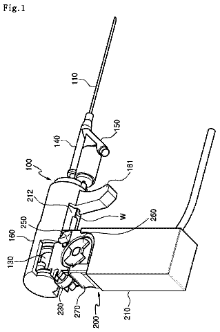
Guide wire insertion apparatus used in catheterization
Disclosed herein is a guide wire insertion device for a catheter procedure.
US 9,956,405 B2 · Assignee: Thyne Global, Inc. · Inventors: Goldwasser; Isy et al.
Sheet 1 of 47 from the published document. All sheets in the USPTO PDF
Described herein are methods and apparatuses for the application of transdermal electrical stimulation (TES) in order to modulate a user's cognitive state to induce a state of calm or relaxation. The apparatuses described herein include neck-worn devices having electrodes (or configured to connect to electrodes, including automatically self-connecting to electrodes) adapted to couple to the midline of the back of user's neck. A neck-worn controller may be configured as a cord, band, wire, torc, necklace, loop, strap, or the like, and may be rigid or semi-rigid and may be worn at least partially around the subject's neck. The controller may controllably apply one or more waveforms to the electrodes of the electrode pad (e.g., patch) to deliver TES adapted to induce or enhance a relaxed cognitive state.
Noninvasive neuromodulation technologies that affect neuronal activity can modulate the pattern of neural activity and cause altered behavior, cognitive states, perception, and motor output without requiring an invasive procedure. For example, transcranial/transdermal electric stimulation (hereinafter “TES”) through scalp electrodes has been used to affect brain function in humans in the form of transcranial alternating current stimulation (hereinafter “tACS”), transcranial direct current stimulation (hereinafter “tDCS”), cranial electrotherapy stimulation (hereinafter “CES”), and transcranial random noise stimulation (hereinafter “tRNS”). Systems and methods for TES have been disclosed (see for example, Capel U.S. Pat. No. 4,646,744; Haimovich et al. U.S. Pat. No. 5,540,736; Besio et al. U.S. Pat. No. 8,190,248; Hagedorn and Thompson U.S. Pat. No. 8,239,030; Bikson et al. U.S. Patent Pu
1 of 47 drawing sheets so far from the published document, cropped to the drawing. Every sheet is in the USPTO PDF.
What the patent claimed, word for word. All of it is now free to use.
All publications and patent applications mentioned in this specification are herein incorporated by reference in their entirety to the same extent as if each individual publication or patent application was specifically and individually indicated to be incorporated by reference.
Described herein are methods and apparatuses for noninvasive neuromodulation of a subject to induce relaxation, calm, mental clarity, and associated mental and physical states. These methods and devices in particular include a neck-worn apparatus which need only contact the user in a single location at the back of the users neck while coupled (e.g., magnetically) to controller and/or power source.
Noninvasive neuromodulation technologies that affect neuronal activity can modulate the pattern of neural activity and cause altered behavior, cognitive states, perception, and motor output without requiring an invasive procedure. For example, transcranial/transdermal electric stimulation (hereinafter “TES”) through scalp electrodes has been used to affect brain function in humans in the form of transcranial alternating current stimulation (hereinafter “tACS”), transcranial direct current stimulation (hereinafter “tDCS”), cranial electrotherapy stimulation (hereinafter “CES”), and transcranial random noise stimulation (hereinafter “tRNS”). Systems and methods for TES have been disclosed (see for example, Capel U.S. Pat. No. 4,646,744; Haimovich et al. U.S. Pat. No. 5,540,736; Besio et al. U.S. Pat. No. 8,190,248; Hagedorn and Thompson U.S. Pat. No. 8,239,030; Bikson et al. U.S. Patent Publication 2011/0144716; and Lebedev et al. U.S. Patent Publication 2009/0177243). tDCS systems with numerous electrodes and a high level of configurability have been disclosed (see for example Bikson et al. U.S. Patent Publications 2012/0209346, 2012/0265261, and 2012/0245653), as have portable TES systems for auto-stimulation (Brocke U.S. Pat. No. 8,554,324). Other portable systems include U.S. patent application Ser. No. 14/639,015, titled “TRANSDERMAL ELECTRICAL STIMULATION DEVICES FOR MODIFYING OR INDUCING COGNITIVE STATE”, filed Mar. 4, 2015, which is a continuation of U.S. patent application Ser. No. 14/320,461, titled “TRANSDERMAL ELECTRICAL STIMULATION DEVICES FOR MODIFYING OR INDUCING COGNITIVE STATE,” filed on Jun. 30, 2014, now U.S. Pat. No. 9,002,458, and U.S. patent application Ser. No. 14/091,121, titled “WEARABLE TRANSDERMAL ELECTRICAL STIMULATION DEVICES AND METHODS OF USING THEM”, filed on Nov. 26, 2013.
Typically, TES has been used therapeutically in various clinical applications, including treatment of pain, depression, epilepsy, and tinnitus. In at least some cases of TES therapeutic use, more data concerning the efficacy of TES in treatment is needed. Despite the research to date on TES neuromodulation, existing systems and methods for TES are lacking in at least some cases regarding the design and use of effective TES waveforms. Available systems are limited regarding the design and delivery of TES waveforms. Moreover, available systems do not permit the user to modulate a predetermined/preconfigured electrical stimulation protocol.
For example, U.S. Pat. No. 8,554,324 to Brocke discloses a mobile system for TES auto-stimulation by a user. Brocke further describes an embodiment wherein a wired or wireless remote control is used to control an electrical stimulation generator, as well as the use of smartphones, cellular telephones, or PDAs as a remote control. However, the systems and methods described by Brocke are lacking in at least some instances for defining, acquiring, and/or delivering effective TES waveforms to a user.
Unfortunately, the majority of the devices, including wearable devices, described to date must be positioned on one more likely two body locations, often including the face and head, which can be uncomfortable and visually unappealing to many consumers. Further, the stimulator electronics interfaces for such devices may be cumbersome, and the small size may limit the power and battery life. Even so-called self-contained devices may project from the body (including the face) making them uncomfortable, and may be easily disrupted.
In addition, the stimulation parameters (e.g., waveforms described to date have proven to be difficult to generalize across users; stimulation parameters that are effective for one set of users may be ineffective and/or uncomfortable (particularly when applied to the head and face) for other users.
Finally, most electrodes for TES (and TENS, transcutaneous electrical nerve stimulation) systems require single-use electrodes applied to the skin (or scalp) by an adhesive. Such electrodes may be reused for a limited number of uses, however they are difficult or impossible to clean, and may dry out, interfering with their ability to reliable make electrical contact with the skin.
It would be beneficial to provide apparatuses for effective neuromodulation (e.g., to affect mood and/or mental state) of a wide number of users that may be worn discretely and comfortably. In particular, such apparatuses (e.g., systems and devices) may also be easily operated and attached to the user, without disrupting the user's hair, skin, glasses, etc. It would also be beneficial to provide electrodes, and in particular electrodes for TES apparatuses, that may be re-used, cleaned and/or rewetted. Described herein are methods and apparatuses that may address these needs.
In general, described herein are methods and apparatuses for the application of transdermal electrical stimulation (TES) in order to modulate a user's cognitive (e.g., mental) state, and in particular to induce a state of calm or relaxation. The apparatuses described herein may include a neck-applied electrode pad (also referred to herein as an electrode patch) that may automatically couple with a neck-worn TMS controller. The electrode patch may be worn (e.g., adhesively coupled) to the skin of a neck to make electrical contact with the midline of the back of user's neck. The electrode pad may include two or more electrodes for contacting the user's skin. A neck-worn controller (TES stimulator) may be configured as a cord, band, wire, torque (torc), necklace, loop, strap, or the like, and may be rigid or semi-rigid. The neck-worn controller may automatically self-couple (e.g., via a magnetic force coupler) to the electrode pad, and may be worn around the subject's neck, e.g., completely or partially around the subject's collar and/or shoulders. The controller (TES stimulator) may controllably apply one or more waveforms to the electrodes of the electrode pad to deliver TES. The waveforms applied are adapted to induce or enhance a cognitive state such as relaxation and/or calm.
Any of these TES apparatuses (devices and systems) described herein may include one or more re-usable electrodes, including cleanable (or self-cleaning), re-wettable (or self-re-wetting) electrodes. For example, a re-wettable electrode may include a “dry” electrode that is automatically wetted before use by applying a conductive material (conductive liquid, such as an aqueous solution, salt solution, conductive gel, etc.) by a vapor. In particular, an electrode may be integrated with a vaporizer (e.g., piezoelectric vaporizer, thermal vaporizer, etc.) that can saturate the electrode's skin-contacting region. The electrode's skin-contacting region may be a porous material (e.g., sponge, etc.). In some variations the apparatus may include a reservoir of the conducive material in contact with the vaporizer that may be used to automatically wet the skin-contacting region. In some variations the apparatus may configured to detect the wetness of the skin-contacting material and regulate the activity of the vaporizer based on feedback from the detected wetness (e.g., the detected resistance or conductivity of the skin-contacting region or the electrical contact with a skin surface). Any of the reusable (e.g., automatically re-wettable and/or self-cleaning) electrodes described herein may be used in whole or in part as part of a skin-contacting electrode, including as part of a physiological monitoring system (e.g., electrocardiogram, electroencephalogram, electromyogram, etc.). In particular, these devices may be part of a TES apparatus, as mentioned.
For example, described herein are neck-worn controller devices for applying transdermal electrical stimulation (TES) to the back of a subject's neck to modify a user's cognitive state and induce a relaxed state. These devices may include: a rigid or semi-rigid torc body configured to be worn around the user's neck; an electrode-coupling region at a middle region of torc body, wherein the electrode-coupling region comprises: a pair of electrode supports arranged adjacent to each other and separated by between 5 mm and 60 mm apart, and a skin-contacting electrode on each of the electrode supports configured to be secured against the user's neck when the torc body is placed around the users neck; and wherein the torc body encloses a control circuitry, a power source and a wireless communication circuitry. In any of the apparatuses described herein an electrode support may be an electrical contact (or may include an electrical contact) connecting a skin-contacting electrode to the control circuitry of the apparatus.
For example, a neck-worn controller device for applying transdermal electrical stimulation (TES) to the back of a subject's neck to modify a user's cognitive state and induce a relaxed state, may include: a rigid or semi-rigid torc body configured to be worn around the user's neck, the torc body extending in a U-shape from a first end to a second end; an electrode-coupling region near middle region of torc body between the first and second ends, wherein the electrode-coupling region comprises: a pair of electrode supports arranged adjacent to each other and separated by between 5 mm and 60 mm apart in a line that is at an angle (e.g., between 90° or perpendicular and 15 degrees) to an axis of the U-shaped torque body, and a skin-contacting reusable and rewettable electrode on each of the electrode supports configured to be secured against the user's neck when the torc body is placed around the users neck; and wherein the torc body encloses a control circuitry, a power source and a wireless communication circuitry.
In general, the spacing between the electrodes (or electrical contacts) connecting to the electrodes (as well as the relative arrangement of the electrodes on the user's neck) in order to evoke a relaxed state may be important, and is typically between 5 mm and 80 mm apart (e.g., 5 mm and 70 mm, 5 mm and 60 mm, 5 mm and 50 mm, 5 mm and 40 mm, 5 mm and 30 mm, 5 mm and 20 mm, 10 mm and 70 mm, 10 mm and 60 mm, 10 mm and 50 mm, 10 mm and 40 mm, etc.). This spacing may be edge-to-edge (nearest edge to nearest edge) or center-to-center between the two electrode contacts and/or electrodes.
Any of these apparatuses may include a control (e.g., on/off, rest, start/stop, rewet, etc.) on the torc body; the control may be electrically connected to the control circuitry and may be any appropriate control, including but not limited to a button, dial, touchpad, slider, etc.
As mentioned, the skin-contacting electrode on each of the electrode supports may comprise a re-wettable electrode, including self-re-wetting electrodes and/or automatically re-wetting electrodes, self-cleaning electrodes, or the like. For example, the skin-contacting electrode on each of the electrode supports may include a mist generator (e.g., vaporizer), and may be coupled to a fluid reservoir on the torc body. The mist generator may be configured to wet one or both of the skin-contacting electrodes. For example a mist generator comprises a piezo driver configured to generate a mist. In some variations the mist generator may be a piezo that is configured to be driven by the same circuitry driving the electrical stimulation (e.g., TES), e.g., at a frequency between 100 KHz to 2 MHz (or greater).
The body (torc body) may be partial rigid, including having one or more rigid portions connected by a flexible region or regions. The torc body may be flexible. The torc body may be any appropriate shape, including U-shaped or C-shaped. The torc body may include a charging port for charging a battery within the torc body. The torc body may be an elongate body that generally extends from a first end to a second end, and fits over the user's neck while holding the electrodes to the back of the user's neck. The torc body may include a hinge on the torc body. The electrode-coupling region may be rigid. The control circuitry, the power source and the wireless communication circuitry may be located at an end of the elongate body. The control circuitry and wireless communication circuitry may be located at a first end region of the elongate body and the power source may be located at a second end region of the elongate body.
As will be described in more detail below, any of the skin-contacting electrodes described herein may be fixed to the neck-worn TES apparatus or may be removably coupled to the neck-worn TES apparatus (e.g., to the electrode supports). For example, the electrodes may be removable and replaceable. The electrode-coupling region may comprise a pair of magnetic attachments. Alternatively or additionally, the skin-contacting electrodes may self-adhere to the TES apparatus allowing for electrical and physical connection via an adhesive, mechanical (e.g., hook-and-loop fasteners, artificial setae, etc.), etc.
Any of the neck-worn TES apparatuses described herein may include one or more speakers and/or an audio connector (jack) for coupling to a speaker or headphones.
In general, any of the neck-worn TES apparatuses may include control circuitry for driving TES through the electrodes and/or regulating the apparatus (including the wetting of the electrodes in some variations). For example, the control circuitry may be configured to deliver electrical energy between the pair of electrodes (or electrical contacts), wherein the electrical energy comprises a carrier wave having a frequency that is greater than 250 Hz that is amplitude modulated at a frequency that is ten percent or less the frequency of the carrier wave, further wherein the amplitude modulation is varied at least once every 40 seconds.
Any of the apparatuses and method described herein may be used (and may be further configured for use) to enhance relaxation. Alternatively or additionally, these apparatuses and methods may be used to lower stress. Stress may be monitored (and in some variations used as feedback, including visual or audio feedback, such as displaying an indicator of the user's stress level (blood pressure, heart rate, skin conductance, etc.) and/or providing controlling feedback (increasing or decreasing stimulation, modulating a stimulation parameter, etc.). Thus, an indicator of stress (or mood) may be used as a control input for controlling/adjusting stimulation including turning on/off, adjusting a parameter of electrical stimulation (frequency, current, duty cycle, peak amplitude, rise time, duration, etc.). Alternatively or additionally, any of the apparatuses and methods described herein may be used to elevate mood. Thus, in general, any of the apparatuses and methods described herein may be useful to reduce stress, reduce anxiety, improve sleep, and/or improve mood.
For example, any of the apparatuses and methods described herein may be used to improve sleep (e.g., one or more of: sleep quality, sleep onset, sleep duration, sleep depth/stage, etc.). An indicator of sleep (e.g., sleep stage/sleep level) may be used as a control input for controlling/adjusting stimulation including turning on/off, adjusting a parameter of electrical stimulation (frequency, current, duty cycle, peak amplitude, rise time, duration, etc.).
The methods described herein may be used to apply neurostimulation to one or more nerves (e.g., nerve bundles) though the skin of the subject's neck at two nearby (e.g., adjacent) locations near the cervical spinal region, such as beneath the hairline but above the C7 cervical region. The two locations may be separated by between about 0.5 and 2.5 inches apart from each other. A single electrode pad may be used to make contact with both sites.
The TES waveforms used to apply energy herein may include a carrier frequency that is between 250 Hz and 50 kHz, and may typically an amplitude between about 1-40 mA (e.g., peak amplitude of between 10 mA and 35 mA, between 10 mA and 30 mA, etc.). The carrier waves may be asymmetric and/or biphasic. Significantly, the applied TES waveforms are modulated by an amplitude modulation envelope that comprises a lower frequency that is at least 10× lower than the frequency of the carrier wave (e.g., a modulation envelope between 10-1 kHz, e.g., between 10-900 Hz, between 10-850 Hz, between 10-800 Hz, etc., and a carrier wave of greater than 2250 Hz, e.g., greater than 300 Hz, 350 Hz, 400 Hz, 450 Hz, 500 Hz, 550 Hz, 600 Hz, 650 Hz, 700 Hz, 750 Hz, 800 Hz, 850 Hz, 900 Hz, 950 Hz, 1 kHz, 2 kHz, 3 kHz, 4 kHz, 5 kHz, 6 kHz, etc., and particularly greater than 5 kHz). The applied waveform may be varied every 5 to 60 seconds, typically by varying the amplitude modulation, alternatively, the waveform may be held for longer durations (e.g., 1 minute to 5 minutes, 1 minute to 10 minutes, 1 minute to 20 minutes, 1 minute to 30 minutes, 1 minute to 40 minutes, etc.). For example, the shape of the amplitude modulation envelope may be changed (e.g., from a sinusoidal envelope to a rectangular envelope, a saw tooth envelope, a triangular envelope, a stair-case envelope, etc.), and the frequency of the amplitude modulation may change separately or at the same time. In some variations the shape of the amplitude modulation envelope is changed by adjusting one or more of: 1) the symmetry ratio (meaning the wave form in time may be non-symmetrical in the time axis; the ratio is an estimate of how non-symmetrical it is), or 2) the flat ratio (meaning the portion(s) of the waveform that remains unchanged in amplitude over as a portion of the wave period), etc. In any of the method and apparatuses (configured to perform these methods) described herein, the waveforms duration may be controlled by the subject; thus subject may continue to apply the waveform until an effect is achieved. For example, a waveform may be applied in a loop that is repeated until terminated by the subject.
In some variations, the rise time of the waveform(s) applied may be controlled to minimize discomfort. For example, the rise-time of a basic pulse waveform applied may be between 1 and 20 microsecond. The rise-time of the pulse may affect both comfort and efficacy; based on preliminary data, it may be beneficial to vary the rise time between 1-20 μs, including varying the rise time continuously between 1 and 20 μs, or picking a rise time that is between 1 and 20 μs and using this, and/or allowing the device and/or use to adjust the rise time (e.g., between 1-20 μs) during application of the waveforms.
As mentioned, the apparatuses described herein include neck-worn controller devices for applying transdermal electrical stimulation (TES) to the back of a subject's neck to modify a user's cognitive state and induce a relaxed state. For example, described herein are neck-worn (also referred to herein as “neck wearable”) that may be comfortably worn around the user's neck and may include: an elongate body configured to be worn at least partially around the user's neck; an electrode-coupling region on the elongate body, the electrode-coupling region comprising: a pair of electrical contacts, and at least one self-connecting (e.g., magnetic, adhesive, etc.) attachment configured to automatically couple the electrical contacts with a complimentary electrical contact on an electrode pad worn on the user's neck when the magnetic attachment is placed adjacent to the electrode pad; and wherein the elongate body encloses a control circuitry, a power source such as a battery, a high voltage source of power for neural stimulation greater than 20 volts, and a wireless communication circuitry.
Any of the neck-worn controller devices may include one or more controls on the body of the device. For example, a neck-worn controller may include a switch, dial, button, slider, etc. The controller may control one or more of (and/or multiple controls may control): power (e.g., on/off/standby), intensity of the TES being applied, communication with a remote (e.g., wireless) controller, playing of the TES (e.g., TES start/pause/stop), selection of a TES waveform, etc.
Any of the neck-worn controller devices described herein may include one or more output such as a display (e.g., LCD, LED, etc.) or other visual output (LED), a tactile output (haptic, e.g., vibrational output, etc.).
The elongate body may be stiff, flexible, or semi-stiff, and may include both stiff and flexible regions (e.g., stiff regions connected by flexible regions). For example, the elongate body may be flexible so that it generally retains its shape but can be “opened” (e.g., when the device is U- or C-shaped) to fit over a user's neck. In general, the elongate body may be U-shaped or C-shaped. In some variations the elongate body include a hinge or hinges that may be used to open the elongate body for placing it on/taking it off of the user's neck.
Any of the apparatuses described herein may include a charging port on the elongate body (e.g., micro USB port). Alternatively or additionally any of these apparatuses may include a non-contact charger (e.g., inductive charging, etc.) or the like.
As mentioned, in general, any of the neck-worn controller devices described herein may include an electrode-coupling region that may be used to secure the neck-worn controller to the user via a connection to an electrode pad that can be separately worn on the user's neck. For example, an electrode-coupling region may be located in a middle region of the elongate body. The electrode-coupling region may generally be rigid or stiff so that it does not shift during wearing or dislodge the coupling attachments (e.g., attachment between the electrical contact and a connector on an electrode pad. Either the connector on the electrode pad or the electrical contact on the neck-worn controller, or both, may include a magnet and/or a magnetic material (that may be attracted to a magnet, such as steel, etc.). This may allow self-connection between the two. The magnetic material, when included, may be any appropriate magnetic material, including “static” magnetic material (e.g., ferrous or magnetic material) and/or electromagnetic materials.
In some variations the electrode-coupling region is at an end of the elongate body.
In general, any of the apparatuses described herein may include a self-connecting or self-engaging connector drawing together the electrode pad and the neck-worn apparatus so that an electrical and/or mechanical connection is made between the two. Although the primary self-engaging connectors described herein are magnetic connectors, any appropriate connector may be used, including adhesive, and/or mechanical self-attaching couplings. However in some variations the electrode-coupling region may comprise a pair of magnetic attachments.
The electrical contact may be integrally formed with the magnetic attachment. For example, the electrical contact may be made through a magnetic (including ferrous) material. In some variations the connector and/or the electrical contacts may be made of an electrically conductive material forming the electrical pathway surround by or adjacent to a magnetic connector (e.g., the electrical contact may be adjacent to or surrounded by the magnetic attachment). One or more self-connecting connectors (magnets) may be included.
In any of these variations, the power source and the wireless communication circuitry are located at an end of the elongate body. For example, the control circuitry and wireless communication circuitry may be located at a first end region of the elongate body and the power source may be located at a second end region of the elongate body. In general, when the neck-worn controller device is configured to be worn around both sides of a user's neck (e.g., is U-shaped), then the two ends (arms) of the U-shaped body may be balanced in shape, size and/or weight.
The electrical contacts may be further adapted to connect to a properly oriented and configured electrode pad to achieve the desired relaxation effect by transdermal electrical stimulation of the neck (e.g., and in some variations just at the neck). In particular, the pair of electrical contacts may be separated by between 1.2 inches and 0.7 inches along the length of the elongate body. This separation may allow them to properly and automatically engage (e.g., self-engage) with the electrode pads described herein for TES of the neck to induce relaxation.
Any of the neck-worn devices described herein may be configured to include one or more speakers (e.g., headphones, etc.). In some variations the apparatuses described herein may be configured to include one or more ear-based electrodes.
In general, the control circuitry may be configured to deliver electrical energy (e.g., TES) between the pair of electrical contacts in order to evoke relaxation in a user by applying TES at the midline of the user's neck between the C1 and T2 region (e.g., C3 and T1, C3 and T2, etc.). For example the control circuitry may be configured to deliver electrical energy comprising a carrier wave having a frequency that is greater than 250 Hz that is amplitude modulated at a frequency that is ten percent or less the frequency of the carrier wave, further wherein the amplitude modulation is varied at least once every 60 seconds (e.g., once every: 50 sec, 45 sec, 40 sec, 35 sec, 30 sec, etc.).
In any of the apparatuses (e.g., systems) described herein, software, firmware, or hardware may be separate from the neck-worn device and may wirelessly connect with the device to regulate, control, select, and/or modify the TES waveforms applied by the apparatus. For example, a user electronics device (e.g., a handheld user electronics device such as a smartphone, wearable electronics, etc.) may wirelessly communicate with the neck-worn controller to transmit or deliver the TES waveform and/or to modify the TES waveform (e.g., increase/decrease intensity, etc.) and/or start/stop/pause operation of the TES waveform delivery.
A neck-worn controller device for applying transdermal electrical stimulation (TES) to the back of a subject's neck to modify a user's cognitive state and induce a relaxed state may include: an elongate body configured to be worn around the user's neck; a rigid electrode-coupling region on the elongate body, the electrode-coupling region comprising: a pair of electrical contacts adjacent to each other, and at least one magnetic attachment configured to automatically couple the electrical contacts with a complimentary electrical contact on an electrode pad worn on the user's neck when the magnetic attachment is placed adjacent to the electrode pad; and control circuitry, a power source and a wireless communication circuitry.
Also described herein are systems for applying transdermal electrical stimulation (TES) to the back of a subject's neck to modify a user's cognitive state and induce a relaxed state, that include an electrode pad to be worn on the back of the neck and a neck-worn controller (and in some variations control software that operates on a controller of a user electronic device and wirelessly communicates with the neck-worn controller).
For example, a system for applying transdermal electrical stimulation (TES) to the back of a subject's neck to modify a user's cognitive state and induce a relaxed state may include: an adhesive electrode pad comprising a first electrode and second electrode on a first side, and a first connector electrically connected to the first electrode and a second connector electrically connected to the second electrode, wherein the first and second connectors are on a second side opposite from the first side; and a neck-worn controller device, the neck-worn controller comprising: an elongate body configured to be worn on a user's neck, an electrode-coupling region on the elongate body having at least one magnetic attachment configured to automatically couple the first connector on the electrode pad to the a first electrical contact on the neck-worn controller device when the magnetic attachment is placed adjacent to the electrode pad, and a control circuitry, a power source and wireless communication circuitry.
The first electrode and the second electrode may be arranged in a line that on the first side that is at angle (e.g. between 90° or perpendicular and 15 degrees, e.g. between 30 degrees and 60 degrees, etc.) to a line connecting the first connector and the second connector electrically connected on the second side.
The adhesive electrode pad(s) may be configured to be worn on the back of a subject's neck so that the first electrode and the second electrode are arranged along a midline of the back of the user's neck. In any of the apparatuses and methods described herein, the pads may be adhered to the neck-worn body before it is placed around the user's neck. Thus, the device may be used to place the pads onto the skin for the user.
In some variations, the applicants have found that it is particularly advantageous when applying TES energy to the back of the user's neck to induce relaxation, to have one of the electrodes (e.g., the second electrode) be larger than the other electrode. For example, a surface area of one of the electrodes may be greater than 1.25 times the surface are of the other electrode (e.g., greater than 1.4×, greater than 1.5×, greater than 1.6×, greater than 1.7×, greater than 1.8×, greater than 1.9×, greater than 2×, etc.).
In general, the neck-worn controller used as part of any of the systems described herein may be any of the neck-worn controllers described above.
For example, a system for applying transdermal electrical stimulation (TES) to the back of a subject's neck to modify a user's cognitive state and induce a relaxed state may include: an adhesive electrode pad comprising a first electrode and second electrode arranged in a vertical line on a first side, and a first connector electrically connected to the first electrode and a second connector electrically connected to the second electrode, wherein the first and second connectors are arranged in a horizontal line perpendicular to the vertical line on a second side that is opposite from the first side; and a neck-worn controller device, the neck-worn controller comprising: an elongate body configured to be worn on a user's neck, an electrode-coupling region on the elongate body having a magnetic attachment configured to automatically electrically and mechanically couple a pair of electrical contacts on the electrode-coupling region with the first and second connectors on the electrode pad when the magnetic attachment is within less than 1 inch from the electrode pad, a control circuitry, a power source, and a wireless communication circuitry.
Also described herein are methods of applying transdermal electrical stimulation (TES) to the back of a user's neck to modify a user's cognitive state and induce a relaxed state. In general such a method may include: attaching a first electrode and second electrode to a back of the user's neck between the user's hairline and the user's C7 cervical region; applying electrical energy between the first electrode and the second electrode to deliver TES; and inducing, in the user, a relaxed mental by the application of TES.
Attaching may comprise adhesively attaching an electrode pad comprising the first and second electrode to the back of a user's neck so that the first and second electrodes are arranged along the midline of the user's neck.
Any of these methods may also include placing a neck-worn controller around the neck of the user and allowing the neck-worn controller to self-engage (including magnetically, mechanically, chemically (e.g., adhesively), etc.) with the electrode pad to form an electrical contact between the neck-worn controller and the first electrode and second electrode.
Applying electrical energy may comprise applying TES by delivering electrical energy between the first electrode and the second electrode, wherein the electrical energy comprises a carrier wave having a frequency that is greater than 250 Hz that is amplitude modulated at a frequency that is ten percent or less the frequency of the carrier wave, further wherein the amplitude modulation is varied at least once every 60 seconds (e.g., once every 55 sec, once every 50 sec, once every 45 sec, once every 40 sec., once every 35 seconds, once every 30 seconds, etc.).
In general, the amplitude modulation may be varied in any appropriate manner, including by varying the shape of an envelope of the amplitude modulation. For example, the envelope shape may be changed between two or more of: a square wave, a step-function, a saw tooth, a triangular shape, a sinusoid, etc. The amplitude modulation may be varied by varying one or both of a symmetry ratio and a flat ratio of the amplitude modulation.
Applying TES to induce relaxation may include applying electrical energy for any appropriate length of time (e.g., for 2 min or greater, 5 minutes or greater, 10 minutes or greater, 15 minutes or greater, etc.).
In general, applying may comprise delivering TES to a nerve fiber, nerve or nerve bundle extending through the user's neck, including spinal nerve, cranial nerves, etc.
For example, a method of applying transdermal electrical stimulation (TES) to the back of a user's neck to modify a user's cognitive state and induce a relaxed state may include: attaching a first electrode and second electrode to a midline of a back of the user's neck between the user's hairline and the user's C7 cervical region, wherein the first and second electrode form part of an electrode pad; placing a neck-worn controller over at least one of the user's shoulders and allowing the neck-worn controller to magnetically self-engage with the electrode pad to form an electrical contact between the neck-worn controller and the first electrode and second electrode; applying TES by delivering electrical energy between the first electrode and the second electrode, wherein the electrical energy comprises a carrier wave having a frequency that is greater than 250 Hz that is amplitude modulated at a frequency that is ten percent or less the frequency of the carrier wave, further wherein the amplitude modulation is varied at least once every 60 (e.g., 55 sec, 50 sec, 45 sec, 40 sec, 35 sec, 30 sec, etc.); and inducing, in the user, a relaxed mental by the application of TES.
In general, any of the methods and apparatuses described herein for self-engaging or attaching the electrode and the device may be configured to mechanically (e.g., loop-and-hook, artificial setae, etc.), chemically (e.g., adhesive), magnetically, or otherwise (including combinations of these) attach. Alternatively, in some variations the apparatuses and methods described herein are configured with the electrode affixed or attached (including integrally attached) to the rest of the apparatus including the electrical contact (or electrical support).
The novel features of the invention are set forth with particularity in the claims that follow. A better understanding of the features and advantages of the present invention will be obtained by reference to the following detailed description that sets forth illustrative embodiments, in which the principles of the invention are utilized, and the accompanying drawings of which:
FIG. 1A is a schematic of a front (user-facing) side of an electrode pad (e.g. patch) or electrical contact that may be applied to a user's skin or neck. The electrode patch may be adhesive, and may include one or more (e.g. a pair of) electrodes for making electrical contact with the user's skin. The electrodes may be covered in a gel or other material to enhance electrical contact. The electrode patch may include an adhesive (e.g., skin adhesive) for securing the electrode patch to the skin of the user's neck. In any of these variations, the electrodes may include a single substrate or a plurality of substrates comprising multiple electrode/skin contact points.
FIG. 1B is a schematic of the back of an electrode patch such as the one shown in FIG. 1A . In this example, a pair of self-connecting connectors is included, which may make a secure electrical connection to the neck-worn controller (TES controller/stimulator). The self-connecting connector in this example is a magnetic connector. Alternatively or additionally, the contact between the patch or patches and the device may be self-adhesive via conductive gel contact.
FIG. 1C is an example of a neck-worn controller (TES controller/stimulator) that may couple to the electrical contact with one or more self-connecting connectors magnetic connectors. In general the neck-worn controller may include electronics (controller, processor, etc.) for applying TES to the electrodes of the electrode patch, a power supply providing power to the electronics, charging circuitry for the battery (e.g., inductive charging, plug-in charging, etc.), and communications circuitry for communicating with one or more remote processors that may be used to control/regulate the application of TES by the device. The neck-worn controller may also include one or more controls for regulating the operation of the system (e.g., on/off, intensity up/down, etc.).
FIG. 1D schematically illustrates a user electronics device, such as a hand-held device having a processor that may be wirelessly (or via a wired connection) coupled to neck-worn controller. The user electronics device may include software, hardware, or firmware for operating the system.
FIGS. 2A-2D illustrate variations of electrode patches that may be used in any of the systems and methods described herein. FIGS. 2A-2D all show the skin-facing, front, side of the electrode patch, and include at least two electrodes.
FIGS. 3A-3D illustrate variations of electrode patches that may be used in any of the systems and methods described herein. FIGS. 3A-3D illustrate the back side of the electrode patch, which may self-connect or couple with the neck-worn controller.
FIGS. 4A and 4B schematically illustrate examples of neck-worn controllers. FIG. 4A shows a neck-worn controller that is worn on just one side of the user's neck (asymmetrically), coupling at one end region to the electrode patch. FIG. 4B shows a neck-worn controller that is worn on either side of the user's neck (symmetrically) coupling in a middle region to an electrode patch.
FIG. 5 illustrates one example of an electrode patch coupled to the midline of the back of a user's neck so that the first and second electrodes are oriented along the user's neck above the C7 region, but beneath the hairline (e.g., between the C1 and C7 regions of the spine).
FIG. 6 shows one example of a neck-worn controller that self-connects to an electrode patch. In FIG. 6 the neck-worn controller include both flexible regions and rigid regions; the region coupling to the electrode patch is rigid.
The description continues in the full USPTO document.
About 6,268 words. The USPTO PDF has it with every drawing.
Fees are due 3.5, 7.5 and 11.5 years after grant. This patent expired on May 1, 2026, so the fee marked "not paid" was the one that went unpaid.
TRANSDERMAL ELECTRICAL STIMULATION AT THE NECK TO INDUCE NEUROMODULATION
Filed May 2017 · published Sep 2017Transdermal electrical stimulation at the neck to induce neuromodulation
Filed May 2017 · granted May 2018Earlier publications, parents and continuations. None of them can still be enforced, or this patent would not be listed.
Prior art cited by the examiner or applicant. Useful when you check your own idea for novelty.
Everything on this page comes from the documents linked above.


