 Lapsed, fee not paid3 drawings
Energy & Sustainability · US 9,954,452 B2
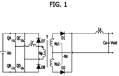
Low voltage direct current (DC)-DC converter
Disclosed herein is a low voltage direct-current (DC)-DC converter.
US 9,954,472 B2 · Assignee: Mitsubishi Electric Corporation · Inventors: Mori; Tatsuya et al.
Sheet 1 of 17 from the published document. All sheets in the USPTO PDF
A control apparatus for an AC rotary machine includes a current detection unit that detects a current of a first winding and a current of a second winding, a basic voltage calculation unit that calculates a basic voltage on the basis of a current command value, a first voltage calculation unit that calculates a voltage command value of the first winding on the basis of the current command value, the basic voltage, and the current of the first winding, and a second voltage calculation unit that calculates a voltage command value of the second winding on the basis of the current command value, the basic voltage, and the current of the second winding. At least the first voltage calculation unit calculates the voltage command value of the first winding by further taking into account the current of the second winding.
In an AC rotary machine having a plurality of windings, a plurality of current control systems interfere with each other due to mutual inductance between the plurality of windings, and therefore a current and a voltage are likely to become oscillatory, making it more difficult to widen a response band of the control systems than when a single system is used. Several methods have been proposed in response to this problem. In one of these methods, employed in a conventional control apparatus for an AC rotary machine, a feedback signal transmitted from a plurality of inverters connected in parallel to a multiphase AC motor to a representative current control system provided on a rotary coordinate system of the AC motor is set at an average value of output currents from the respective inverters. Further, a feedback signal transmitted to an imbalance suppressing current control system provide
1 of 17 drawing sheets so far from the published document, cropped to the drawing. Every sheet is in the USPTO PDF.
What the patent claimed, word for word. All of it is now free to use.
This application is a National Stage of International Application No. PCT/JP2013/080235 filed Nov. 8, 2013, the contents of all of which are incorporated herein by reference in their entirety.
This invention relates to a control apparatus for an AC rotary machine having at least a first winding and a second winding.
In an AC rotary machine having a plurality of windings, a plurality of current control systems interfere with each other due to mutual inductance between the plurality of windings, and therefore a current and a voltage are likely to become oscillatory, making it more difficult to widen a response band of the control systems than when a single system is used. Several methods have been proposed in response to this problem.
In one of these methods, employed in a conventional control apparatus for an AC rotary machine, a feedback signal transmitted from a plurality of inverters connected in parallel to a multiphase AC motor to a representative current control system provided on a rotary coordinate system of the AC motor is set at an average value of output currents from the respective inverters. Further, a feedback signal transmitted to an imbalance suppressing current control system provided on the rotary coordinate system of the AC motor is set at a differential value of the output currents from the respective inverters.
As a result, the imbalance suppressing current control system acts to equalize the output currents from the respective inverters, and therefore respective currents of windings of respective phases in the multiphase AC motor can be balanced.
Further, an unbalanced current can be reduced in a similar manner by the action of the current control system likewise in inverters that are connected in parallel using an external reactor.
By balancing the output currents of the respective inverters in this manner, the external reactor can be reduced in size or omitted, and control exhibiting high responsiveness can be realized (PTL 1, for example).
Furthermore, in a conventional control apparatus for an AC rotary machine, a non-interference voltage calculation unit is provided for each of respective control circuits of inverters INV1 to INVN that drive respective windings of a three-phase, N-layer winding motor, and an excitation command value I.sub.O*, a torque command value I.sub.T*, d, q axis current command values i.sub.1d*, i.sub.1q* obtained by dividing I.sub.O* and I.sub.T* by a number N of turns in the multiplex winding, and a primary side frequency ω are taken therein. d, q axis voltage set values v.sub.1d*, v.sub.1q* are then calculated from these values, whereupon non-interference control of the three-phase multiplex winding motor is realized by performing vector control (PTL 2, for example). CITATION LIST Patent Literature
Japanese Patent No. 2614788
Japanese Patent Application Publication No. H11-262293 SUMMARY OF INVENTION Technical Problem
However, the following problems occur in the prior art.
In PTL 1, a large number of complicated operations must be performed in the representative current control system and the imbalance suppressing current control system using the currents of both the first and second windings. Moreover, during non-interference control based on detected currents such as the currents of the first and second windings, the effects of interference cannot be eliminated completely due to time wastage between detection of the first and second winding currents and implementation of the operations of the representative current control system and the imbalance suppressing current control system such that a voltage is applied to the plurality of inverters.
It is therefore difficult to realize an equal current response to that of a conventional single system winding, and this difficulty is particularly evident when using a low-cost microcomputer having a low operation speed.
In PTL 2, the non-interference voltage calculation unit is provided for each of the respective control circuits of the inverters INV1 to INVN in order to improve the feedforward response. This configuration includes a power supply frequency ω of the AC rotary machine, as indicated by Equation
in PTL 2, and therefore a large number of complicated operations are required. The response achieved as a result, however, is merely of an equivalent level to the response of a conventional single system winding, and moreover, a feedback gain cannot be increased sufficiently. Hence, an ability to suppress a disturbance voltage generated as a result of rapid variation in the speed of a three-phase, duplex winding motor, for example, is poor.
An object of this invention is therefore to obtain a control apparatus for an AC rotary machine that includes at least a first winding and a second winding and performs control operations on two rotary axes, with which a reduction in a number of operations, an improvement in response, and an improvement in an ability to suppress disturbances are achieved. Solution to Problem
To solve the problems described above, a control apparatus for an AC rotary machine according to this invention is a control apparatus for an AC rotary machine that includes a first winding and a second winding and performs control operations on two rotary axes, having: a current detection unit that detects a current of the first winding and a current of the second winding, respectively; a basic voltage calculation unit that calculates a basic voltage on the basis of a current command value and an electric constant of the AC rotary machine; a first voltage calculation unit that calculates a voltage command value of the first winding on the basis of the current command value, the basic voltage, and the current of the first winding; a second voltage calculation unit that calculates a voltage command value of the second winding on the basis of the current command value, the basic voltage, and the current of the second winding; a first voltage application unit that applies a voltage to the first winding of the AC rotary machine on the basis of the voltage command value of the first winding; and a second voltage application unit that applies a voltage to the second winding of the AC rotary machine on the basis of the voltage command value of the second winding, wherein the first voltage calculation unit calculates the voltage command value of the first winding on the basis of the current command value, the basic voltage, the current of the first winding, and also the current of the second winding. Advantageous Effects of Invention
In the control apparatus for an AC rotary machine according to this invention, the first voltage calculation unit calculates the voltage command value of the first winding on the basis of the current of the first winding, the basic voltage, and the current command value. The second voltage calculation unit calculates the voltage command value of the second winding on the basis of the current of the second winding, the basic voltage, and the current command value. In this case, at least the first voltage calculation unit calculates the voltage command value of the first winding by further taking into account the current of the second winding.
Therefore, during feedback control based on the detected values of the respective currents of the first and second windings according to this invention, there is no need to generate voltage command values for the first and second windings using the currents of both the first and second windings, as in PTL 1. In other words, the voltage command value of the first winding can be calculated by at least the first voltage calculation unit alone on the basis of the current of the other winding, i.e. the second winding. Interference is interactive, but even with this simple configuration, interference between the respective current control systems can be suppressed simply by taking measures in relation to the first voltage calculation unit. As a result, a response at least at a level close to that of a conventional AC rotary machine can be realized.
Moreover, there is no need for a configuration in which a non-interference voltage calculation unit is provided for each of the respective control circuits of INV1 to INVN and the power supply frequency ω of the AC rotary machine is included, and as a result, there is no need to perform a large number of complicated operations.
Furthermore, in this invention, a single basic voltage may be calculated in relation to at least the response of the sum of the currents of the first and second windings on the basis of the current command value and the electric constant. Therefore, in a high frequency band, the current response can be improved using nothing more than the basic voltage that takes into account only an electric constant such as the inductance and winding resistance of the rotary machine. As a result, a response at least at a level close to that of a conventional single system winding can be realized.
As described above, an effect of suppressing interference between the plurality of current control systems, an effect of improving the current response to the current command value, an effect of being able to output a voltage command value that corresponds to the current command value even in a high frequency band, and an effect of being able to realize a higher level of response that that of a conventional single system winding even in a multiplex winding using the action of the current response to the current command value are obtained. Moreover, the current response can be improved by means of non-interference likewise in relation to feedback, and therefore a disturbance suppression ability can also be secured.
Furthermore, in this invention, the number of operations performed during both feedforward and feedback may be increased. For example, a second voltage calculation unit that calculates a voltage command value on the basis of the current of the first winding and so on may be provided in addition to the power supply frequency item and the current of the second winding. In this case, the ability to suppress a disturbance voltage and the current response to the current command value are improved even further.
Hence, according to this invention, the number of operations is reduced in comparison with the prior art even in a multiplex winding, and as a result, a dramatic improvement in response that does not occur in the prior art is obtained.
FIG. 1 is a circuit block diagram showing a first embodiment of a control apparatus for an AC rotary machine according to this invention.
FIG. 2 is a view showing a first winding and a second winding of the AC rotary machine used in this invention.
FIG. 3 is an equivalent circuit diagram showing the AC rotary machine having the windings shown in FIG. 2 .
FIG. 4 is a diagram showing the circuit diagram of FIG. 3 as an equivalent circuit of a q axis current.
FIG. 5 is a diagram showing the circuit diagram of FIG. 3 as an equivalent circuit of a d axis current.
FIG. 6 is a circuit block diagram showing a second embodiment of the control apparatus for an AC rotary machine according to this invention.
FIG. 7 is a view showing a transmission characteristic from a differential voltage to a differential current on the d axis according to the second embodiment of this invention.
FIG. 8 is a view showing the transmission characteristic from the differential voltage to the differential current on the q axis according to the second embodiment of this invention.
FIG. 9 is a circuit block diagram showing a third embodiment of the control apparatus for an AC rotary machine according to this invention.
FIG. 10 is a view showing a transmission characteristic from a sum voltage to a sum current on the d axis according to the third embodiment of this invention.
FIG. 11 is a view showing the transmission characteristic from the sum voltage to the sum current on the q axis according to the third embodiment of this invention.
FIG. 12 is a circuit block diagram showing a fourth embodiment of the control apparatus for an AC rotary machine according to this invention.
FIG. 13 is a circuit block diagram showing a fifth embodiment of the control apparatus for an AC rotary machine according to this invention.
FIG. 14 is a circuit block diagram showing sixth and seventh embodiments of the control apparatus for an AC rotary machine according to this invention.
FIG. 15 is a circuit block diagram showing an eighth embodiment of the control apparatus for an AC rotary machine according to this invention.
FIG. 16 is a circuit block diagram showing a ninth embodiment of the control apparatus for an AC rotary machine according to this invention.
FIG. 17 is a circuit block diagram showing a tenth embodiment of the control apparatus for an AC rotary machine according to this invention.
Various embodiments of a control apparatus for an AC rotary machine according to this invention will be described below with reference to the drawings. First Embodiment
FIG. 1 shows an overall configuration of a first embodiment of the control apparatus for an AC rotary machine according to this invention. In the drawing, an AC rotary machine 1 a includes two three-phase windings constituted by first windings U 1 , V 1 , W 1 and second windings U 2 , V 2 , W 2 (see FIG. 2 ). Note that in all of the following embodiments, a permanent magnet type synchronous rotary machine having two windings will be described as the AC rotary machine 1 a , but this invention may be applied similarly to any permanent magnet type synchronous rotary machine or field winding type synchronous rotary machine having two or more windings.
A position detection unit 2 a is constituted by a Hall element, a resolver, an encoder, or the like that detects a rotation position θ of the AC rotary machine 1 a . A technique of estimating the position on the basis of a current of the first winding and a current of the second winding, which are detected by current detection units 3 , 4 to be described below, may be used instead.
The current detection unit 3 is constituted by a shunt resistor, a Hall element, or the like that detects currents i 1 u , i 1 v , i 1 w passing respectively through the first windings U 1 , V 1 , W 1 of the AC rotary machine 1 a . The current detection unit 4 is constituted by a shunt resistor, a Hall element, or the like that detects currents i 2 u , i 2 v , i 2 w passing respectively through the second windings U 2 , V 2 , W 2 of the AC rotary machine 1 a.
A basic voltage calculation unit 5 a calculates basic voltages vdF*, vqF* on two rotary axes (d-q axes) on the basis of current command values id*, iq* issued to the AC rotary machine 1 a from the outside and an electric constant stored internally in the AC rotary machine 1 a.
A first voltage calculation unit 6 a calculates voltage command values v 1 u *, v 1 v *, v 1 w * of the first windings on the basis of the current command values id*, iq*, the currents i 1 u , i 1 v , i 1 w of the first windings, detected by the current detection unit 3 , the currents i 2 u , i 2 v , i 2 w of the second windings, detected by the current detection unit 4 , and the basic voltages vdF*, vqF*.
A second voltage calculation unit 7 a calculates voltage command values v 2 u *, v 2 v *, v 2 w * of the second windings on the basis of the current command values id*, iq*, the currents i 2 u , i 2 v , i 2 w of the second windings, detected by the current detection unit 4 , and the basic voltages vdF*, vqF*.
A first voltage application unit 8 is a power converter such as an inverter or a matrix converter that applies the voltage command values v 1 u *, v 1 v *, v 1 w * of the first windings to the first windings U 1 , V 1 , W 1 of the AC rotary machine 1 a by performing modulation processing on the voltage command values v 1 u *, v 1 v *, v 1 w * using an existing technique such as PWM or PAM.
A second voltage application unit 9 is a power converter such as an inverter or a matrix converter that applies the voltage command values v 2 u *, v 2 v *, v 2 w * of the second windings to the second windings U 2 , V 2 , W 2 of the AC rotary machine 1 a by performing modulation processing on the voltage command values v 1 u *, v 1 v *, v 1 w * using an existing technique such as PWM or PAM.
The first voltage calculation unit 6 a includes coordinate converters 10 , 11 , 12 , subtractors 13 , 14 , current controllers 15 , 16 , and adders 17 , 18 . The second voltage calculation unit 7 a includes coordinate converters 11 , 22 , a subtractor 19 , a current controller 20 , and an adder 21 . The coordinate converter 11 is shared with the first voltage calculation unit 6 a.
The coordinate converter 10 calculates currents i 1 d , i 1 q on the two rotary axes (the d-q axes) on the basis of the currents i 1 u , i 1 v , i 1 w detected by the current detection unit 3 and the rotation position θ detected by the position detection unit 2 a.
The subtractor 13 subtracts the current command values id*, iq* respectively from the currents i 1 d , i 1 q obtained by the coordinate converter 10 , and outputs resulting deviations di 1 d (=id*−i 1 d ), di 1 q (=iq*−i 1 q ).
The current controller 15 calculates voltage command values v 1 d *, v 1 q * on the two rotary axes (the d-q axes) by performing proportional integral (PI) control such that di 1 d (=id*−i 1 d ) and di 1 q (=iq*−i 1 q ), obtained from the subtractor 13 , align with each other at zero, or in other words become equal to each other.
The coordinate converter 11 calculates currents i 2 d , i 2 q on the two rotary axes (the d-q axes) on the basis of the currents i 2 u , i 2 v , i 2 w detected by the current detection unit 4 and the rotation position θ detected by the position detection unit 2 .
The subtractor 14 subtracts the current command values id*, iq* respectively from the currents i 2 d , i 2 q obtained by the coordinate converter 11 , and outputs resulting deviations di 2 d (=id*−i 2 d ), di 2 q (=iq*−i 2 q ).
The current controller 16 calculates compensation voltage command values V 1 d _ h *, V 1 q _ h * on the two rotary axes (the d-q axes) by performing proportional integral control or proportional (P) control such that di 2 d (=id*−i 2 d ) and di 2 q (=iq*−i 2 q ), obtained from the subtractor 14 , align with each other at zero.
The adder 17 adds the voltage command values v 1 d *, v 1 q * on the two rotary axes (the d-q axes), obtained from the current controller 15 , to the voltage command values v 1 d _ h *, v 1 q _ h * on the two rotary axes (the d-q axes), obtained from the current controller 16 , and outputs resulting voltage command values V 1 d ′*, V 1 q ′* on the two rotary axes (the d-q axes).
The adder 18 calculates voltage command values V 1 d ″*, V 1 q ″* on the two rotary axes (the d-q axes) by adding the voltage command values V 1 d ′*, V 1 q ′* on the two rotary axes (the d-q axes), obtained from the adder 17 , to the voltage command values vdF*, vqF* on the two rotary axes (d-q axes), obtained from the basic voltage calculation unit 5 a.
The coordinate converter 12 converts the voltage command values V 1 d ″*, V 1 q ″* on the two rotary axes (the d-q axes), obtained from the adder 17 , into the voltage command values v 1 u *, v 1 v *, v 1 w * of the first windings.
In the second voltage calculation unit 7 a , the subtractor 19 subtracts the current command values id*, iq* respectively from the currents i 2 d , i 2 q obtained from the coordinate converter 11 , and outputs resulting deviations di 2 d (=id*−i 2 d ), di 2 q (=iq*−i 2 q ).
The current controller 20 calculates voltage command values v 2 d *, v 2 q * on the two rotary axes (the d-q axes) by performing proportional integral control such that di 2 d (=id*−i 2 d ) and di 2 q (=iq*−i 2 q ), obtained from the subtractor 19 , align with each other at zero.
The adder 21 calculates voltage command values v 2 d ′*, v 2 q ′* on the two rotary axes (the d-q axes) by adding the voltage command values v 2 d *, v 2 q * on the two rotary axes (the d-q axes), obtained from the current controller 20 , to the voltage command values vdF*, vqF* on the two rotary axes (d-q axes), obtained from the basic voltage calculation unit 5 a.
The coordinate converter 22 converts the voltage command values V 2 d ′*, V 2 q ′* on the two rotary axes (the d-q axes), obtained from the adder 21 , into the voltage command values v 2 u *, v 2 v *, v 2 w * of the second windings.
Next, the AC rotary machine 1 a will be described. As shown in FIG. 2 , the AC rotary machine 1 a is housed in a stator (not shown) of a rotary machine such that a three-phase winding including a set of windings U 1 , V 1 , W 1 connected at a neutral point N 1 and a three-phase winding including a set of windings U 2 , V 2 , W 2 connected at a neutral point N 2 are not electrically connected to each other.
Although the two windings are not electrically connected, the two windings are magnetically coupled by a magnetic circuit formed in the AC rotary machine, and thus the two windings are coupled so as to form precisely a primary side and a secondary side of a transistor.
Accordingly, an equivalent circuit of the U 1 phase and the U 2 phase, which are disposed in parallel, can be expressed as shown in FIG. 3 . In the drawing, Vu 1 , Vu 2 denote terminal voltages from the respective neutral points, R denotes an armature winding resistance, eu denotes an induced voltage, Mu denotes mutual inductance of the armature winding, and Lu-Mu denotes leakage inductance (self-inductance of armature winding—mutual inductance of armature winding). Further, n denotes a turn ratio in terms of the transistor.
Note that of these values, Lu-Mu and Mu in particular are different to values used to control a motor having a single layer winding, and indicate values between two phases of multiple layers disposed in parallel. Further, in a typical AC rotary machine, parallel windings have an identical number of turns, and therefore n=1. Moreover, at this time, equivalent circuits of the U 1 phase and the U 2 phase, the V 1 phase and the V 2 phase, and the W 1 phase and the W 2 phase are identical, and therefore, in a case where the characteristics of the three phases are equal, even when coordinate conversion is performed on the two rotary axes (the d-q axes) from the U, V, and W phases, an equivalent circuit on the two rotary axes (the d-q axes) is identical to the equivalent circuit shown in FIG. 3 .
As described above, the plurality of windings of the AC rotary machine are magnetically coupled, and therefore an interference voltage is generated between the windings. When an equivalent circuit of the AC rotary machine having three phases, namely the U, V, and W phases, is subjected to coordinate conversion on the two rotary axes (the d-q axes), circuit configurations of the respective phases are identical to that of FIG. 3 , as described above. FIG. 4 , meanwhile, shows an equivalent circuit on the q axis in the form of a block diagram.
In the drawing, V 1 q , V 2 q respectively denote q axis winding voltages applied to the first and second winding sets, while i 1 q , i 2 q respectively denote q axis winding currents applied to the first and second winding sets. Further, in the drawing, voltages expressed by Viq 12 , Viq 21 indicate interference voltages from the other winding set. Note that s in the drawing denotes a differential operator of a Laplace transform, R denotes a resistance value, Lq denotes a q axis self-inductance, and Mq denotes a q axis mutual inductance.
FIG. 4 shows an equivalent circuit on the q axis of the two rotary axes (the d-q axes), but as shown in FIG. 5 , an equivalent circuit on the d axis is configured similarly.
During normal vector control of an AC rotary machine, current control is performed independently on the two rotary axes (the d-q axes), but in an AC rotary machine having a plurality of winding sets, interference voltages act mutually thereon, as described above, and these interference voltages are input into the current control systems as disturbances. As is evident from FIG. 4 , the interference voltage is proportionate to a differential value of each winding current, and therefore increases steadily as the current is caused to respond at increasing speed. It is therefore more difficult to improve the response of the current control system than when current control is performed on a single set of windings.
PTL 1 responds to this problem by setting the feedback signal input into the representative current control system at the average value of the output currents of the respective inverters, and setting the feedback signal input into the imbalance suppressing current control system provided on the rotary coordinate system of the AC motor at the differential value of the output currents of the respective inverters. As a result, the imbalance suppressing current control system acts to equalize the output currents of the respective inverters, and therefore the respective currents of the windings of the respective phases in the multiphase AC motor are balanced.
With this configuration, however, calculations must be performed using both the currents of the first windings on the two rotary axes (the d-q axes) and the currents of the second windings on the two rotary axes (the d-q axes) when calculating the average value and the differential value of the currents. Moreover, to implement the operations of the representative current control system and the imbalance suppressing current control system, the voltages of the first windings and the voltages of the second windings must be calculated, and therefore a large number of operations are required.
In contrast to the method of dealing with the interference voltage according to PTL 1, described above, the first embodiment employs a simple configuration in which the voltage command values of the first windings are compensated for on the basis of the currents passing through the second windings.
Returning to FIG. 1 , in the first voltage calculation unit 6 a , the compensation voltage command values V 1 d _ h *, V 1 q _ h * on the two rotary axes (the d-q axes) are calculated by the current controller 16 on the basis of the currents i 2 u , i 2 v , i 2 w of the second windings.
In the current controller 16 , a voltage for compensating for Vid 12 in FIG. 5 is output as V 1 d _ h *, and a voltage for compensating for Viq 12 in FIG. 4 is output as V 1 q _ h *. By compensating for Vid 12 and Viq 12 , the effect of interference on i 1 d and i 1 q is reduced such that i 1 d and i 1 q are stabilized. As a result, Vid 21 , Vid 12 , which are obtained by multiplying sMd, sMq by i 1 d and i 1 q , respectively, are also stabilized, leading to stabilization of i 2 d , i 2 q.
According to the first embodiment, therefore, by employing a configuration in which the voltages of the first windings are compensated for (corrected by) the currents of the second windings, which is simple and requires few calculations, a non-interference effect that is at least equal to that of PTL 1 (an improvement in current response that is equal to PTL 1) can be obtained without the need for the complicated current control system configuration of PTL 1.
As described above, however, with a method of improving the current control response by means of non-interference control using detected currents, such as the method of compensating for the voltages of the first windings with the currents of the second windings, as described in PTL 1 and the first embodiment, the interference voltage increases steadily as the currents are caused to respond at increasing speed. A compensation voltage with which to compensate for a large interference voltage is affected by time wastage between detection of the currents and output of the compensation voltage. This effect is particularly evident when using a low-cost microcomputer having a low operation speed, making it difficult to eliminate the effect of interference completely when the current control response is improved.
In response to this problem, PTL 2 discloses an example in which the current response is improved by adding a non-interference voltage, as expressed by [Numeral 1] in PTL 2. With this configuration, however, [Numeral 1] is calculated for each of the control circuits corresponding to the respective windings, and therefore a large number of operations are required. As a result, this configuration cannot easily be packaged in a low-cost microcomputer.
In the first embodiment, on the other hand, the basic voltages vdF*, vqF* on the two rotary axes (d-q axes) are simply calculated by the basic voltage calculation unit 5 a on the basis of current command values id*, iq*.
Next, the basic voltage calculation unit 5 a will be described.
Equation (1), shown below, is a relational expression indicating a relationship between the voltage and the current on the two rotary axes (d-q axes) in the AC rotary machine 1 a . Here, ω denotes an electric angular velocity and φ denotes a flux linkage. Equation
is equivalent to an expression that takes into account a speed electromotive force resulting from an armature reaction corresponding to the inductances Ld, Lq, Md, Mq in addition to the relationship between the voltage and the current expressed by the block diagrams shown in FIGS. 4 and 5 , described above.
[ Numeral 1 ] [ v 1 d v 1 q v 2 d v 2 q ] = [ R + sL d - ω L q sM d - ω M q ω L d R + s L q ω M d sM q sM d - ω M q R + sL d - ω L q ω M d sM q ω L d R + sL q ] [ i 1 d i 1 q i 2 d i 2 q ] + [ 0 ωϕ 0 ωϕ ] ( 1 )
A process for deriving the basic voltages vdF*, vqF* from Equation
will be described below.
The basic voltage calculation unit 5 a calculates the basic voltages vdF*, vqF* on the two rotary axes (d-q axes) on the basis of the current command values id*, iq*, and therefore, first, in Equation (1), the currents are given by id*=i 1 d =i 2 d , iq*=i 1 q =i 2 q (Equation (2)).
[ Numeral 2 ] [ v 1 d v 1 q v 2 d v 2 q ] = [ R + sL d - ω L q sM d - ω M q ω L d R + s L q ω M d sM q sM d - ω M q R + sL d - ω L q ω M d sM q ω L d R + sL q ] [ i d * i q * i d * i q * ] + [ 0 ωϕ 0 ωϕ ] ( 2 )
Here, the first and third rows and the second and fourth rows on the right side are respectively identical, and therefore Equations
and (4), shown below, are obtained. [Numeral 3] v .sub.1d =v .sub.2d ={R+s ( L .sub.d +M .sub.d)}.Math. i .sub.d*−ω( L .sub.q +M .sub.q).Math. i .sub.q*
v .sub.1q =v .sub.2q ={R+s ( L .sub.q +M .sub.q)}.Math. i .sub.q*+ω{( L .sub.d +M .sub.d).Math. i .sub.d*+φ}
By calculating the basic voltages vdF*, vqF* on the two rotary axes (d-q axes) as v 1 d =vdF* in Equation
and v 1 q =vqF* in Equation
from the current command values id*, iq* and the relationships in Equations
and (4), the required basic voltages vdF*, vqF* are output on the basis of the current command values id*, iq*, and as a result, the response of the AC rotary machine is improved.
Further, a method of calculating the basic voltages in order to improve the current response using even simpler operations than those of Equations
and
will be described below. In Equations
and (4), the electric angular velocity ω is affected by both an inertia moment of the AC rotary machine itself and an inertia moment of a load connected to the AC rotary machine, and therefore responds at a lower speed than the current.
In a comparatively low frequency band such as the electric angular velocity ω, non-interference control based on detected currents such as that described in PTL 1 and this invention, in which the voltage command values of the first windings are compensated for on the basis of the currents passing through the second windings, can be used. However, a frequency band relating to items based on the current command values and the electric constants of the AC rotary machine is equal to a high frequency band in the vicinity of a current control limit, and therefore a current control response can be secured in relation to these items by performing compensation using the basic voltages.
Hence, by omitting the items relating to the electric angle ω in Equations
and
as in Equations
and (6), shown below, the current response can be improved using a simple operation expressed by the current commands and the electric constants (the armature winding resistance R and the armature winding inductances Ld, Lq, Md, Mq) of the AC rotary machine 1 a. [Numeral 4] v .sub.dF *={R+s ( L .sub.d +M .sub.d)}.Math. i .sub.d*
v .sub.qF *={R±s ( L .sub.q +M .sub.q)}.Math. i .sub.q*
In the first embodiment of this invention, as described above, by employing a configuration in which the voltage command values of the first windings are compensated for on the basis of the currents passing through the second windings, a current control response band including the band of the electric angular frequency ω is secured without the need for a large number of operations, as in PTL 1. Therefore, in a band where non-interference control based on the detected currents cannot be applied, a current control response can be secured at the level of a single layer winding using the basic voltages calculated on the basis of the current command values and the electric constants.
At this time, non-interference control based on the detected currents can be applied in the band of the electric angular frequency ω, and therefore a response is secured at the level of a single layer winding simply, without the need to include items relating to the electric angular frequency ω, as in PTL 2.
Hence, the current control response can be raised to the level of a single layer winding type AC rotary machine by means of a simple configuration. Second Embodiment
FIG. 6 shows a configuration of a second embodiment of the control apparatus for an AC rotary machine according to this invention. In FIG. 6 , identical reference symbols to those used in the first embodiment have been allocated to identical or corresponding parts. The second embodiment differs from the first embodiment in having a first voltage calculation unit 6 b that includes a differential current calculator 211 , a subtractor 212 , a current controller 213 , an adder 214 , and a differential voltage calculation unit 215 .
First, the differential current calculator 211 subtracts the currents i 1 d , i 1 q of the first windings, obtained from the coordinate converter 10 , respectively from the currents i 2 d , i 2 q of the second windings, obtained from the coordinate converter 11 , and outputs resulting differential currents Δid, Δiq as differences between the currents of the first windings and the currents of the second windings.
The subtractor 212 subtracts predetermined differential current command values Δid*, Δiq* respectively from the currents Δid, Δiq obtained by the differential current calculator 211 , and outputs resulting deviations dΔid (=Δid*−Δid), dΔiq (=Δiq*−Δiq). The differential current command values Δid*, Δiq* are both set at zero.
The current controller 213 calculates differential voltages Vd_dif*, Vq_dif* by performing proportional integral control or proportional control such that the deviations dΔid (=Δid*−Δid) and dΔiq (=Δiq*−Δiq) obtained from the subtractor 212 both reach zero.
Hence, the differential voltage calculation unit 215 is constituted by the subtractor 212 and the current controller 213 , and outputs the differential voltages Vd_dif*, Vq_dif* on the basis of the differential currents Δid, Δiq, which serve as the differences between the currents of the first windings and the currents of the second windings, and the differential current command values Δid*, Δiq*.
The adder 214 calculates voltage command values V 1 d ′*, V 1 q ′* on the two rotary axes (the d-q axes) by adding the differential voltages vd_dif*, vq_dif* obtained from the current controller 213 respectively to the voltage command values v 1 d *, v 1 q * on the two rotary axes (the d-q axes), obtained from the current controller 15 .
By configuring the control apparatus for an AC rotary machine as shown in FIG. 6 , the differential currents serving as the differences between the currents of the first windings and the currents of the second windings can be determined by the differential current calculator 211 , the deviations between the differential currents and the differential current command values can be determined by the subtractor 212 , and differential voltages v 1 d _dif*, v 1 q _dif* can be added to the current controller 214 in order to bring the deviations to zero. Hence, the voltage command values v 1 d ′*, v 1 q ′* of the first windings act to suppress the differential currents, and as a result, the effect of the interference voltage described in the first embodiment can be suppressed.
The manner in which the interference voltage is suppressed by calculating the voltage command values of the first windings on the basis of the differential currents, as described above, will now be described in detail. First, Equations
and (8), shown below, are obtained from FIGS. 4 and 5 . [Numeral 5] V .sub.1d −V .sub.2d ={R+s ( L .sub.d −M .sub.d)}.Math.( i .sub.1d −i .sub.2d)
V .sub.1q −V .sub.2q ={R+s ( L .sub.q −M .sub.q)}.Math.( i .sub.1q −i .sub.2q)
Here, Vid 12 =sMdi 2 d , Vid 21 =sMdi 1 d , Viq 12 =sMdi 2 q , and Viq 21 =sMqi 1 q.
In Equations
and (8), a transmission characteristic from the differential voltages (V 1 d −V 2 d , V 1 q −V 2 q ), which are expressed as differences between first and second voltage groups, to the differential currents (i 1 d −i 2 d , i 1 q −i 2 q ) is a simple first order lag system, as shown in FIGS. 7 and 8 , and therefore an interference voltage such as that shown in FIGS. 4 and 5 does not exist. Hence, by designing the current controller 213 that compensates for the voltage command values of the first windings on the basis of the differential currents as a controller having as a control subject a simple first order lag system such as that shown in FIGS. 7 and 8 , the effect of the interference voltage can be reduced, with the result that imbalance between the currents of the first windings and the currents of the second windings can be suppressed.
In the second embodiment, the effect of the interference voltage can be suppressed by correcting the voltage command values of the first windings using the differential voltages Vd_dif*, Vq_dif*, obtained from the current controller 213 , on the basis of the differential currents, and as a result, an improvement in the current control response can be obtained.
In the second embodiment of this invention, as described above, the differential currents between the currents of the first windings and the currents of the second windings are determined in the first voltage calculation unit, differential voltages are output by the differential voltage calculation unit 215 on the basis of the differential currents and the differential current command values, and the voltage command values of the first windings are corrected on the basis of the output differential voltages. In contrast to the first embodiment, therefore, by designing the current controller 212 so as to have a simple first order lag system from the differential voltage to the differential current as a control subject, imbalance between the currents of the first windings and the currents of the second windings can be suppressed without being affected by an interference voltage.
The description continues in the full USPTO document.
About 7,174 words. The USPTO PDF has it with every drawing.
Fees are due 3.5, 7.5 and 11.5 years after grant. This patent expired on April 24, 2026, so the fee marked "not paid" was the one that went unpaid.
CONTROL APPARATUS FOR AC ROTARY MACHINE
Filed Nov 2013 · published Jul 2016Control apparatus for AC rotary machine
Filed Nov 2013 · granted Apr 2018Earlier publications, parents and continuations. None of them can still be enforced, or this patent would not be listed.
Prior art cited by the examiner or applicant. Useful when you check your own idea for novelty.
Everything on this page comes from the documents linked above.