 Lapsed, fee not paid3 drawings
Software & Apps · US 9,952,891 B2
Anomalous usage of resources by a process in a software defined data center
The present disclosure is related to systems and methods for analysis of anomalous usage of a resource.
US 9,952,901 B2 · Assignee: Intel Corporation · Inventors: Wu; Haihua et al.
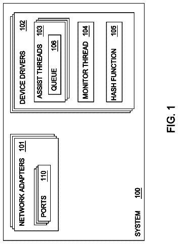
Sheet 1 of 16 from the published document. All sheets in the USPTO PDF
Described herein are technologies related to enforcing thread dependency using a hybrid scoreboard. An encoded video information that includes a plurality of threads is received, a first set and a second set of threads from the plurality of thread is determined, the first and second sets of threads are assigned to a hardware and a software, respectively, and dependency threads in the first and second sets of threads is enforced.
Multi-thread decoding of encoded video information may be performed with different threads. For example, when the encoded video information has been encoded according to a particular video codec standard, the decoding tools that may be used to perform decoding tasks are designed to meet hardware constraints, usage constraints, or other criteria A decoding thread for a current macro block or coding unit may depend on one or more other decoding threads for the current macro block or coding unit and/or, one or more other macro block or coding unit. For example, preliminary analysis of thread dependencies is performed, and the dependencies are updated during process of decoding to allow accurate determination of which threads are currently executable or “runnable.” A thread is considered to be runnable, for example, if its completion does not depend on any other uncompleted threads. In this
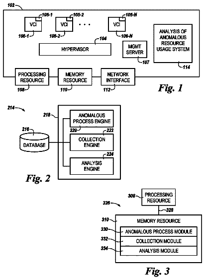
1 of 16 drawing sheets so far from the published document, cropped to the drawing. Every sheet is in the USPTO PDF.
What the patent claimed, word for word. All of it is now free to use.
Multi-thread decoding of encoded video information may be performed with different threads. For example, when the encoded video information has been encoded according to a particular video codec standard, the decoding tools that may be used to perform decoding tasks are designed to meet hardware constraints, usage constraints, or other criteria
A decoding thread for a current macro block or coding unit may depend on one or more other decoding threads for the current macro block or coding unit and/or, one or more other macro block or coding unit. For example, preliminary analysis of thread dependencies is performed, and the dependencies are updated during process of decoding to allow accurate determination of which threads are currently executable or “runnable.” A thread is considered to be runnable, for example, if its completion does not depend on any other uncompleted threads. In this example, the decoding threads may generally consume a lot of power especially in a software scoreboard-based approach where software polling is utilized to verify the completed/uncompleted tasks.
As such, there is a need to address various concerns about power reduction during the decoding process.
FIG. 1 illustrates an example block diagram of a computing device used in accordance with implementations described herein.
FIG. 2 illustrates an example graphics processing unit (GPU) workload with a plurality of threads that include a dependent thread and associated threads as described in implementations herein.
FIGS. 3A and 3B illustrate an example dispatch order for an 8×8 block thread granularity High Efficiency Video Coding (HEVC) Intra-Prediction algorithm.
FIG. 4 illustrates histogram that may be utilized by a statistical algorithm to determine best dependencies in a given plurality of thread.
FIG. 5 illustrates an example flowchart illustrating an example method for implementing a hybrid scoreboard to enforce dependency thread as described herein.
FIG. 6 is a block diagram of a data processing system according to an embodiment.
FIG. 7 is a block diagram of an embodiment of a processor having one or more processor cores, an integrated memory controller, and an integrated graphics processor.
FIG. 8 is a block diagram of one embodiment of a graphics processor which may be a discrete graphics processing unit, or may be graphics processor integrated with a plurality of processing cores.
FIG. 9 is a block diagram of an embodiment of a graphics processing engine for a graphics processor.
FIG. 10 is a block diagram of another embodiment of a graphics processor.
FIG. 11 illustrates thread execution logic including an array of processing elements employed in one embodiment of a graphics processing engine.
FIG. 12 is a block diagram illustrating a graphics processor execution unit instruction format according to an embodiment.
FIG. 13 is a block diagram of another embodiment of a graphics processor which includes a graphics pipeline, a media pipeline, a display engine, thread execution logic, and a render output pipeline.
FIG. 14A is a block diagram illustrating a graphics processor command format according to an embodiment and FIG. 14B is a block diagram illustrating a graphics processor command sequence according to an embodiment.
FIG. 15 illustrates exemplary graphics software architecture for a data processing system according to an embodiment.
Described herein is a technology for enforcing thread dependency using a hybrid scoreboard-based approach. For example, the hybrid scoreboard-based approach utilizes a combination of a hardware scoreboard and a software scoreboard to enforce the thread dependency. A hardware scoreboard works faster with lower power consumption, but can only handle limited number of thread dependencies due to higher cost. A software scoreboard is flexible, can handle large number of thread dependencies without incurring extra cost. But it is slower and consumes more power In this example, the enforcement of the thread dependency is not limited by dependency entries and furthermore, efficient power usage is obtained in the process.
For example, a device antenna receives an encoded video information that includes a plurality of thread. The plurality of threads may include the dependency threads, which are one or more threads that may have to wait for another thread to finish its workload before the dependency thread starts its own execution.
In an implementation, a first set of threads (with long waiting time) and a second set of threads (with short waiting time) are derived from the plurality of threads based on a dispatch order, a spatial location, and the like, of each thread in the plurality of threads. For example, the first set of thread may include those threads that are dispatched later in time as compared to the threads from the second set of thread. In this example, the first set of threads may be assumed to have long waiting time and is assigned/processed through a hardware scoreboard; while the second set of threads, which is assumed to have short waiting time, is assigned and processed through a software scoreboard.
With the setup described above, the hardware scoreboard helps to enforce dependency by blocking a current thread until all of the first set of threads have been cleared (i.e., finished its workload) with very low power cost. Furthermore, there is a high probability that the second set of threads (i.e., short waiting time) may have finished their workloads at the time that the dependent thread polls the software scoreboard. As such, most software polling is avoided to save power.
FIG. 1 is an example block diagram of a computing device 100 that may be used in accordance with implementations described herein. The computing device 100 may include a central processing unit (CPU) 102 , a memory device 104 , one or more applications 106 that may be stored in a storage 108 , a hybrid scoreboard 110 , a graphics hardware 112 , and a display device 114 .
Example computing device 100 may be a laptop computer, desktop computer, tablet computer, mobile device, or server, among others. In this example, the computing device 100 may include the CPU 102 configured to execute stored instructions, as well as the memory device 104 that stores instructions, which are executable by the CPU 102 . The CPU 102 may control and coordinate the overall operations of the computing device 100 . Furthermore, the CPU 102 may be a single core processor, a multi-core processor, a computing cluster, or any number of other configurations.
In an implementation, the memory device 104 may include a main memory of the computing device 100 . In addition, the memory device 104 may include any form of random access memory (RAM), read-only memory (ROM), flash memory, or the like. For example, the memory device 104 may be one or more banks of memory chips or integrated circuits. In this example, the CPU 102 may have direct access to the memory device 104 through a bus connection (not shown).
The instructions that are executed by the CPU 102 may be used to execute any of a number of applications 106 residing within the storage device 108 of the computing device 100 . The applications 106 may be any types of applications or programs having graphics, graphics objects, graphics images, graphics frames, video, or the like, to be displayed to a user (not shown) through the display device 114 . The storage device 108 may include a hard drive, an optical drive, a thumb drive, an array of drives, or any combinations thereof.
In an implementation, the hybrid scoreboard 110 may include a processor, firmware, hardware scoreboard, software scoreboard or a combination thereof to enforce dependency threads, for example, from a received encoded video information. That is, the hybrid scoreboard 110 may reduce software polling in a pure software scoreboard-based approach. In this implementation, the hybrid scoreboard 110 utilizes the combination of the hardware and software scoreboard-based approach to overcome dependency limitation/entries of the hardware scoreboard-based approach. For example, a particular set of threads may be implemented using, for example, the hardware scoreboard while another set of threads may be implemented using the software scoreboard that uses software polling.
In an implementation, the hybrid scoreboard 110 may be configured to determine a first set of thread, which may include longer waiting times as compared to another set (e.g., second set) of threads from the plurality of thread. In this implementation, the first set of threads (i.e., later dispatched associated threads) may be assigned to the hardware scoreboard (not shown) while the second set of threads (i.e., earlier dispatched associated threads) may be assigned to the software scoreboard (not shown). The long and short waiting times for the first and second set of threads, respectively, may refer to the amount of time that a particular thread has to stall its execution until its associated threads (i.e., threads to which the current thread is dependent upon) have finished.
In an implementation, the hybrid scoreboard 110 inherits the full flexibility of the software-based score boarding including the unlimited number of dependencies to be enforced. At the same time, the hybrid scoreboard 110 may further facilitate reduction of the probability of software polling and saves power by using the hardware scoreboard.
With continuing reference to FIG. 1 , the graphics hardware 112 may act as an interface to the display device 114 , which may refer to any on-board or plug in devices such as a graphics processing unit (GPU), video cards/players/instructions, audio/music players, and the like. In this implementation, the graphics hardware 112 may facilitate, for example, relaying of completed thread dispatches from a buffer to the display device 114 .
FIG. 2 illustrates an example graphics processing unit (GPU) workload 200 with a plurality of threads that include a dependent thread and associated threads as described in implementations herein.
In an implementation, the GPU workload 200 may include a neighbor thread dependency—where a current thread such as a current thread 202 may wait to consume its neighbor's (i.e., associated threads) produced result. In this implementation, the current thread 202 may be referred to as the dependent thread as it has to wait for the results of neighbor associated threads 204 , 206 , 208 and 210 .
As shown, the left image of FIG. 2 depicts the neighbor thread dependency for the GPU workload 200 while the right image illustrates a software scoreboard, which reflects a status of the plurality of threads 202 - 210 . For example, a status of each thread on a particular spatial location at the left image is shown at a corresponding spatial location in the software scoreboard. A status that includes “1” indicates that the particular thread is finished while a status “0” indicates that the thread has yet to finish its task/s.
To guarantee dependencies in software scoreboarding, a user may maintain a memory surface to hold the software scoreboard. When one dependent software thread is triggered (e.g., current thread 202 ), it polls the software scoreboard until all of its associated threads 204 , 206 , 208 and 210 have finished. At the end of each thread, the thread updates its entry in the software scoreboard to “1” as shown.
In a case of hardware scoreboard, the hardware scoreboard may guarantee the dependency with a specific hardware scoreboard mechanism. For example, although the hardware scoreboard may be present, there is no need to implement software polling. Additionally, the dependent thread such as the current thread 202 may not be invoked until all of its associated threads 204 , 206 , 208 and 210 have finished. In this example, the hardware scoreboard solution has a power and performance advantage; however, the hardware scoreboard may be limited by its maximum number of dependency entries such as when limited to eight entries.
In the present implementations described herein, the hybrid scoreboard 110 utilizes both the hardware scoreboard and software scoreboard to minimize the software polling probability to thereby considerably improve the power efficiency.
FIGS. 3A and 3B illustrate an example dispatch order 300 for an 8×8 block thread granularity High Efficiency Video Coding (HEVC) Intra-Prediction algorithm. The dependency threads in the dispatch order 300 , for example, may be enforced using the hybrid scoreboarding as described in present implementations herein.
As shown in FIG. 3A , a block 302 is a dependent thread containing a dispatch order 256 . The dispatch order may include the time instant when a particular thread was issued. As such, the waiting time may be based upon the amount of the current dispatch order for each block in the dispatch order 300 . For example, associated threads (i.e., shaded blocks) as shown in blocks 304 - 320 may have dispatch orders 63 , 106 , 107 , 110 , 111 , 122 , 123 , 126 , and 127 , respectively. Similarly, associated threads in blocks 322 - 336 may have dispatch orders 213 , 215 , 221 , 223 , 245 , 247 , 253 and 255 , respectively. In these examples, the blocks 322 - 336 were issued later in time based from their higher dispatch order numbers as compared to the blocks 304 - 320 . As such, assuming that all threads have similar workloads, the blocks 322 - 336 may finish later in time as compared to the blocks 304 - 320 . As described herein, the blocks 322 - 336 may be referred to as belonging to a first set of threads while the blocks 304 - 320 may be referred to as a second set of thread.
In an implementation, the hybrid scoreboard 110 may be configured to process the first set of threads (i.e., blocks 322 - 336 ) through its hardware scoreboard while the second set of threads (i.e., blocks 304 - 320 ) is processed through the software scoreboard. Since the current dependent thread at block 302 does not continue to execute until all of the associated threads in blocks 304 - 336 are finished, the waiting time may depend upon the time when the last associated thread finishes (e.g., block 336 that includes dispatch order 255 ). In other words, the dependency penalty for the dependent block 302 is substantially impacted by the finish time of the last completed associated thread 255 . In the implementation described above, the hardware scoreboard may help enforce the dependency by blocking the current thread 302 until all of the first set of threads have been cleared without power cost.
Although there is a need to perform software polling for the second set of threads that are processed by the software scoreboard, there is a high probability that the second set of threads may have finished their workloads at the time that the dependent thread 302 polls the software scoreboard as described in FIG. 2 above. As such, most software polling in the implementations described herein is avoided to save power.
FIG. 3B illustrates a real algorithm scenario where the dependency threads may be different based on spatial position. As described in FIG. 3A above, the total dependency count is 17 (i.e., shown in shaded gray), and the relative spatial positions from the current thread are (−1, −1), (−1, 0), (−1, 1), (−1, 2), (−1, 3), (−1, 4), (−1, 5), (−1, 6), (−1, 7), (0, −1), (1, −1), (2, −1), (3, −1), (4, −1), (5, −1), (6, −1), and (7, −1), respectively. In FIG. 3B , an individual thread may depend alone on a subset of these 17 dependencies.
For example, the dependency thread at block 342 with a dispatch order 288 has a different dependency pattern based on its current spatial location. As shown, the dependency thread or block 342 includes 13 dependency locations. That is, blocks 328 - 336 are associated threads that include dispatch orders 223 , 245 , 247 , 253 , and 255 , respectively, and blocks 340 , 356 , 372 , 388 , 404 , 420 , 436 , and 452 are associated threads that include dispatch orders 266 , 267 , 270 , 271 , 282 , 283 , 286 , and 287 , respectively.
In another example, a dependency block 406 with dispatch order 304 may include a different dependency pattern based on its current spatial location. For example, the dependency block 406 includes 9 dependency locations. That is, blocks 388 - 396 , 404 , 420 , 436 , and 452 are associated that include dispatch orders 271 , 293 , 295 , 301 , 303 , 282 , 283 , 286 , and 287 , respectively.
In the above examples, assuming that the hardware scoreboard of the hybrid scoreboard 110 has 8 dependency entries limit and that the dependency entries are fixed on the kernel level, a similar selection is made (i.e., 8 dependencies) for all the software threads in the same kernel.
In an implementation, a statistical algorithm or method is utilized to determine the best 8 dependencies. An example statistical algorithm using a histogram is further discussed in details below.
FIG. 4 is an example histogram 400 that may be utilized by the statistical algorithm to determine the best dependencies in a given plurality of thread. For example, the hybrid scoreboard 110 may utilize the histogram 400 to determine the 8 dependencies for the software scoreboard.
As shown, each dependency location may occupy a cell 402 in the histogram 400 . For example, each associated threads 304 - 334 in FIG. 3A occupies a corresponding cell 402 . By getting the dispatch order information and knowing the dependency for each thread, an “M” number, for example, is chosen/picked for the first set of threads and the histogram cell 402 is updated based on relative spatial position of each thread in the first set of threads. In this example, the “M” number may be any positive integer value from 1 to the hardware dependency amount limit.
When the “M” number is set to equal the hardware dependency amount limit of 8, the 8 first set of threads for the dependency thread block 302 may include 213 / 215 / 221 / 223 / 245 / 247 / 253 / 255 , and corresponding histogram cells 402 are cell (−1, 0), cell (−1, 1), cell (−1, 2), cell (−1, 3), cell (−1, 4), cell (−1, 5), cell (−1, 6), and cell (−1, 7), respectively. For each histogram cell value one is added.
For the dependent thread 288 in FIG. 3B , 8 first set of threads are occupied by threads 266 / 267 / 270 / 271 / 282 / 283 / 286 / 287 , and their related histogram cells are cell (0, −1), cell (1, −1), cell (2, −1), cell (3, −1), cell (4, −1), cell (5, −1), cell (6, −1), and cell (7, −1), respectively. For each histogram cell one is added.
For another dependent thread 304 , 8 first set of threads (i.e., later locations) are occupied by threads 282 / 283 / 286 / 287 / 293 / 295 / 301 / 303 , and their related histogram cells are cell (0, −1), cell (1, −1), cell (2, −1), cell (3, −1), cell (−1, 0), cell (−1, 1), cell (−1, 2), and cell (−1, 3), respectively. For each histogram cell value one is added and if the current thread's N dependency locations is less than M, the N cells are updated accordingly.
With continuing reference to FIG. 4 , a selection of higher “M” histogram value cells is made and the corresponding spatial locations for the selected “M” histogram value cells are assigned to the hardware scoreboard dependency. In other words, the remaining dependency locations are handled by the software scoreboard.
With more thread workload information, the hardware dependency location assignment may be improved by adding a weight for each thread's contribution. For example, if a pre-knowledge that thread 255 at block 336 has an above average workload in terms of execution time, then a higher weight may be added to its contribution. In another example, if the information for the associated thread 213 at block 322 has a longer than average workload as compared to the thread 255 at block 336 , then an increase in weight may be added to raise the contribution of the thread 213 at block 322 .
Based from the histogram 400 and the resulting weights for the corresponding cells 402 , the 8 dependencies for the software scoreboard may be chosen by the hybrid scoreboard 110 .
FIG. 5 shows an example process flowchart 500 illustrating an example method for implementing a hybrid scoreboard to enforce dependency thread as described herein. The hybrid scoreboard, for example, utilizes the combination of HW and/or SW threads. The order in which the method is described is not intended to be construed as a limitation, and any number of the described method blocks may be combined in any order to implement the method, or alternate method. Additionally, individual blocks may be deleted from the method without departing from the spirit and scope of the subject matter described herein. Furthermore, the method may be implemented in any suitable hardware, software, firmware, or a combination thereof, without departing from the scope of the invention.
At block 502 , receiving an encoded video information that includes a plurality of threads is performed. For example, the plurality of threads may include dependent thread block 302 that includes the dispatch order 256 and other associated threads. In this example, the threads may include a set of operations i.e., workloads that is executed for decoding of the encoded video information.
At block 504 , determining a first set and a second set of threads from the plurality of thread is performed. For example, the first set of thread may include those threads that were dispatched later in time as compared to the second set of thread. In other words, the first set of thread has higher number of dispatch orders as compared to the dispatch orders contained in the second set of threads.
At block 506 , assigning the first and second set of thread to a HW and SW, respectively, is performed. For example, the first set of threads is assigned to the HW section while the second set of threads is assigned to the SW section of the computing device. In this example, a statistical algorithm may be implemented to determine the best dependencies for both hardware and software scoreboards.
At block 508 , enforcing dependency threads in the first and second set of thread is performed.
Overview— FIGS. 6-9
FIG. 6 is a block diagram of a data processing system 600 , according to an embodiment. The data processing system 600 includes one or more processors 602 and one or more graphics processors 608 , and may be a single processor desktop system, a multiprocessor workstation system, or a server system having a large number of processors 602 or processor cores 607 . In on embodiment, the data processing system 600 is a system on a chip integrated circuit (SOC) for use in mobile, handheld, or embedded devices.
An embodiment of the data processing system 600 can include, or be incorporated within a server-based gaming platform, a game console, including a game and media console, a mobile gaming console, a handheld game console, or an online game console. In one embodiment, the data processing system 600 is a mobile phone, smart phone, tablet computing device or mobile Internet device. The data processing system 600 can also include, couple with, or be integrated within a wearable device, such as a smart watch wearable device, smart eyewear device, augmented reality device, or virtual reality device. In one embodiment, the data processing system 600 is a television or set top box device having one or more processors 602 and a graphical interface generated by one or more graphics processors 608 .
The one or more processors 602 each include one or more processor cores 607 to process instructions which, when executed, perform operations for system and user software. In one embodiment, each of the one or more processor cores 607 is configured to process a specific instruction set 609 . The instruction set 609 may facilitate complex instruction set computing (CISC), reduced instruction set computing (RISC), or computing via a very long instruction word (VLIW). Multiple processor cores 607 may each process a different instruction set 609 which may include instructions to facilitate the emulation of other instruction sets. A processor core 607 may also include other processing devices, such a digital signal processor (DSP).
In one embodiment, the processor 602 includes cache memory 604 . Depending on the architecture, the processor 602 can have a single internal cache or multiple levels of internal cache. In one embodiment, the cache memory is shared among various components of the processor 602 . In one embodiment, the processor 602 also uses an external cache (e.g., a Level 3 (L3) cache or last level cache (LLC)) (not shown) which may be shared among the processor cores 607 using known cache coherency techniques. A register file 606 is additionally included in the processor 602 which may include different types of registers for storing different types of data (e.g., integer registers, floating point registers, status registers, and an instruction pointer register). Some registers may be general-purpose registers, while other registers may be specific to the design of the processor 602 .
The processor 602 is coupled to a processor bus 610 to transmit data signals between the processor 602 and other components in the system 600 . The system 600 uses an exemplary ‘hub’ system architecture, including a memory controller hub 616 and an input output (I/O) controller hub 630 . The memory controller hub 616 facilitates communication between a memory device and other components of the system 600 , while the I/O controller hub (ICH) 630 provides connections to I/O devices via a local I/O bus.
The memory device 620 , can be a dynamic random access memory (DRAM) device, a static random access memory (SRAM) device, flash memory device, or some other memory device having suitable performance to serve as process memory. The memory 620 can store data 622 and instructions 621 for use when the processor 602 executes a process. The memory controller hub 616 also couples with an optional external graphics processor 612 , which may communicate with the one or more graphics processors 608 in the processors 602 to perform graphics and media operations.
The ICH 630 enables peripherals to connect to the memory 620 and processor 602 via a high-speed I/O bus. The I/O peripherals include an audio controller 646 , a firmware interface 628 , a wireless transceiver 626 (e.g., Wi-Fi, Bluetooth), a data storage device 624 (e.g., hard disk drive, flash memory, etc.), and a legacy I/O controller for coupling legacy (e.g., Personal System 2 (PS/2)) devices to the system. One or more Universal Serial Bus (USB) controllers 642 connect input devices, such as keyboard and mouse 644 combinations. A network controller 634 may also couple to the ICH 630 . In one embodiment, a high-performance network controller (not shown) couples to the processor bus 610 .
FIG. 7 is a block diagram of an embodiment of a processor 700 having one or more processor cores 702 A-N, an integrated memory controller 714 , and an integrated graphics processor 708 . The processor 700 can include additional cores up to and including additional core 702 N represented by the dashed lined boxes. Each of the cores 702 A-N includes one or more internal cache units 704 A-N. In one embodiment each core also has access to one or more shared cached units 706 .
The internal cache units 704 A-N and shared cache units 706 represent a cache memory hierarchy within the processor 700 . The cache memory hierarchy may include at least one level of instruction and data cache within each core and one or more levels of shared mid-level cache, such as a level 2 (L2), level 3 (L3), level 4 (L4), or other levels of cache, where the highest level of cache before external memory is classified as the last level cache (LLC). In one embodiment, cache coherency logic maintains coherency between the various cache units 706 and 704 A-N.
The processor 700 may also include a set of one or more bus controller units 716 and a system agent 710 . The one or more bus controller units manage a set of peripheral buses, such as one or more Peripheral Component Interconnect buses (e.g., PCI, PCI Express). The system agent 710 provides management functionality for the various processor components. In one embodiment, the system agent 710 includes one or more integrated memory controllers 714 to manage access to various external memory devices (not shown).
In one embodiment, one or more of the cores 702 A-N include support for simultaneous multi-threading. In such embodiment, the system agent 710 includes components for coordinating and operating cores 702 A-N during multi-threaded processing. The system agent 710 may additionally include a power control unit (PCU), which includes logic and components to regulate the power state of the cores 702 A-N and the graphics processor 708 .
The processor 700 additionally includes a graphics processor 708 to execute graphics processing operations. In one embodiment, the graphics processor 708 couples with the set of shared cache units 706 , and the system agent unit 710 , including the one or more integrated memory controllers 714 . In one embodiment, a display controller 711 is coupled with the graphics processor 708 to drive graphics processor output to one or more coupled displays. The display controller 711 may be separate module coupled with the graphics processor via at least one interconnect, or may be integrated within the graphics processor 708 or system agent 710 .
In one embodiment a ring based interconnect unit 712 is used to couple the internal components of the processor 700 , however an alternative interconnect unit may be used, such as a point to point interconnect, a switched interconnect, or other techniques, including techniques well known in the art. In one embodiment, the graphics processor 708 couples with the ring interconnect 712 via an I/O link 713 .
The exemplary I/O link 713 represents at least one of multiple varieties of I/O interconnects, including an on package I/O interconnect which facilitates communication between various processor components and a high-performance embedded memory module 718 , such as an eDRAM module. In one embodiment each of the cores 702 -N and the graphics processor 708 use the embedded memory modules 718 as shared last level cache.
In one embodiment cores 702 A-N are homogenous cores executing the same instruction set architecture. In another embodiment, the cores 702 A-N are heterogeneous in terms of instruction set architecture (ISA), where one or more of the cores 702 A-N execute a first instruction set, while at least one of the other cores executes a subset of the first instruction set or a different instruction set.
The processor 700 can be a part of or implemented on one or more substrates using any of a number of process technologies, for example, Complementary metal-oxide-semiconductor (CMOS), Bipolar Junction/Complementary metal-oxide-semiconductor (BiCMOS) or N-type metal-oxide-semiconductor logic (NMOS). Additionally, the processor 700 can be implemented on one or more chips or as a system on a chip (SOC) integrated circuit having the illustrated components, in addition to other components.
FIG. 8 is a block diagram of one embodiment of a graphics processor 800 which may be a discreet graphics processing unit, or may be graphics processor integrated with a plurality of processing cores. In one embodiment, the graphics processor is communicated with via a memory mapped I/O interface to registers on the graphics processor and via commands placed into the processor memory. The graphics processor 800 includes a memory interface 814 to access memory. The memory interface 814 can be an interface to local memory, one or more internal caches, one or more shared external caches, and/or to system memory.
The graphics processor 800 also includes a display controller 802 to drive display output data to a display device 820 . The display controller 802 includes hardware for one or more overlay planes for the display and composition of multiple layers of video or user interface elements. In one embodiment the graphics processor 800 includes a video codec engine 806 to encode, decode, or transcode media to, from, or between one or more media encoding formats, including, but not limited to Moving Picture Experts Group (MPEG) formats such as MPEG-2, Advanced Video Coding (AVC) formats such as H.264/MPEG-4 AVC, as well as the Society of Motion Picture & Television Engineers (SMPTE) 421M/VC-1, and Joint Photographic Experts Group (JPEG) formats such as JPEG, and Motion JPEG (MJPEG) formats.
In one embodiment, the graphics processor 800 includes a block image transfer (BLIT) engine 804 to perform two-dimensional (2D) rasterizer operations including, for example, bit-boundary block transfers. However, in one embodiment, 2D graphics operations are performed using one or more components of the graphics-processing engine (GPE) 810 . The graphics-processing engine 810 is a compute engine for performing graphics operations, including three-dimensional (8D) graphics operations and media operations.
The GPE 810 includes a 8D pipeline 812 for performing 8D operations, such as rendering three-dimensional images and scenes using processing functions that act upon 3D primitive shapes (e.g., rectangle, triangle, etc.). The 3D pipeline 812 includes programmable and fixed function elements that perform various tasks within the element and/or spawn execution threads to a 3D/Media sub-system 815 . While the 3D pipeline 812 can be used to perform media operations, an embodiment of the GPE 810 also includes a media pipeline 816 that is specifically used to perform media operations, such as video post processing and image enhancement.
In one embodiment, the media pipeline 816 includes fixed function or programmable logic units to perform one or more specialized media operations, such as video decode acceleration, video de-interlacing, and video encode acceleration in place of, or on behalf of the video codec engine 806 . In on embodiment, the media pipeline 816 additionally includes a thread spawning unit to spawn threads for execution on the 3D/Media sub-system 815 . The spawned threads perform computations for the media operations on one or more graphics execution units included in the 3D/Media sub-system.
The 3D/Media subsystem 815 includes logic for executing threads spawned by the 3D pipeline 812 and media pipeline 816 . In one embodiment, the pipelines send thread execution requests to the 3D/Media subsystem 815 , which includes thread dispatch logic for arbitrating and dispatching the various requests to available thread execution resources. The execution resources include an array of graphics execution units to process the 3D and media threads. In one embodiment, the 3D/Media subsystem 815 includes one or more internal caches for thread instructions and data. In one embodiment, the subsystem also includes shared memory, including registers and addressable memory, to share data between threads and to store output data.
3D/Media Processing— FIG. 9
FIG. 9 is a block diagram of an embodiment of a graphics processing engine 910 for a graphics processor. In one embodiment, the graphics processing engine (GPE) 910 is a version of the GPE 310 shown in FIG. 3 . The GPE 910 includes a 3D pipeline 912 and a media pipeline 916 , each of which can be either different from or similar to the implementations of the 3D pipeline 312 and the media pipeline 316 of FIG. 3 .
In one embodiment, the GPE 910 couples with a command streamer 903 , which provides a command stream to the GPE 3D and media pipelines 912 , 916 . The command streamer 903 is coupled to memory, which can be system memory, or one or more of internal cache memory and shared cache memory. The command streamer 903 receives commands from the memory and sends the commands to the 3D pipeline 912 and/or media pipeline 916 . The 3D and media pipelines process the commands by performing operations via logic within the respective pipelines or by dispatching one or more execution threads to the execution unit array 914 . In one embodiment, the execution unit array 914 is scalable, such that the array includes a variable number of execution units based on the target power and performance level of the GPE 910 .
A sampling engine 930 couples with memory (e.g., cache memory or system memory) and the execution unit array 914 . In one embodiment, the sampling engine 930 provides a memory access mechanism for the scalable execution unit array 914 that allows the execution array 914 to read graphics and media data from memory. In one embodiment, the sampling engine 930 includes logic to perform specialized image sampling operations for media.
The specialized media sampling logic in the sampling engine 930 includes a de-noise/de-interlace module 932 , a motion estimation module 934 , and an image scaling and filtering module 936 . The de-noise/de-interlace module 932 includes logic to perform one or more of a de-noise or a de-interlace algorithm on decoded video data. The de-interlace logic combines alternating fields of interlaced video content into a single fame of video. The de-noise logic reduces or remove data noise from video and image data. In one embodiment, the de-noise logic and de-interlace logic are motion adaptive and use spatial or temporal filtering based on the amount of motion detected in the video data. In one embodiment, the de-noise/de-interlace module 932 includes dedicated motion detection logic (e.g., within the motion estimation engine 934 ).
The motion estimation engine 934 provides hardware acceleration for video operations by performing video acceleration functions such as motion vector estimation and prediction on video data. The motion estimation engine determines motion vectors that describe the transformation of image data between successive video frames. In one embodiment, a graphics processor media codec uses the video motion estimation engine 934 to perform operations on video at the macro-block level that may otherwise be computationally intensive to perform using a general-purpose processor. In one embodiment, the motion estimation engine 934 is generally available to graphics processor components to assist with video decode and processing functions that are sensitive or adaptive to the direction or magnitude of the motion within video data.
The image scaling and filtering module 936 performs image-processing operations to enhance the visual quality of generated images and video. In one embodiment, the scaling and filtering module 936 processes image and video data during the sampling operation before providing the data to the execution unit array 914 .
In one embodiment, the graphics processing engine 910 includes a data port 944 , which provides an additional mechanism for graphics subsystems to access memory. The data port 944 facilitates memory access for operations including render target writes, constant buffer reads, scratch memory space reads/writes, and media surface accesses. In one embodiment, the data port 944 includes cache memory space to cache accesses to memory. The cache memory can be a single data cache or separated into multiple caches for the multiple subsystems that access memory via the data port (e.g., a render buffer cache, a constant buffer cache, etc.). In one embodiment, threads executing on an execution unit in the execution unit array 914 communicate with the data port by exchanging messages via a data distribution interconnect that couples each of the sub-systems of the graphics processing engine 910 .
Execution Units— FIGS. 10-12
The description continues in the full USPTO document.
About 6,549 words. The USPTO PDF has it with every drawing.
Fees are due 3.5, 7.5 and 11.5 years after grant. This patent expired on April 24, 2026, so the fee marked "not paid" was the one that went unpaid.
POWER EFFICIENT HYBRID SCOREBOARD METHOD
Filed Dec 2014 · published Jun 2016Power efficient hybrid scoreboard method
Filed Dec 2014 · granted Apr 2018Earlier publications, parents and continuations. None of them can still be enforced, or this patent would not be listed.
Prior art cited by the examiner or applicant. Useful when you check your own idea for novelty.
Everything on this page comes from the documents linked above.