Lapsed, fee not paid5 drawings
Telecom & Networks · US 9,948,575 B2
Issuing method for forwarding adjacency link
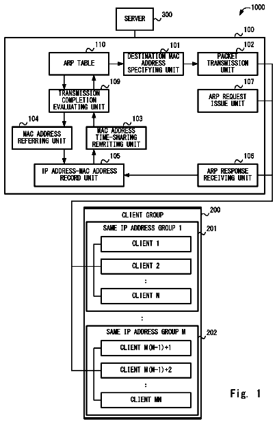
An issuing method for a forwarding adjacency link and a logical node are provided.
US 9,948,615 B1 · Assignee: Pure Storage, Inc. · Inventors: Davis; John D.
Sheet 1 of 6 from the published document. All sheets in the USPTO PDF
A method for storage unit communication is provided. The method includes detecting an event associated with a loss of trust for the data stored within a storage unit and encrypting, at the storage unit, data that is being transmitted along an outbound path from the storage unit to a requestor, wherein the encrypting is responsive to detecting the event.
Solid-state memory, such as flash, is currently in use in solid-state drives (SSD) to augment or replace conventional hard disk drives (HDD), writable CD (compact disk) or writable DVD (digital versatile disk) drives, collectively known as spinning media, and tape drives, for storage of large amounts of data. Flash and other solid-state memories have characteristics that differ from spinning media. Yet, many solid-state drives are designed to conform to hard disk drive standards for compatibility reasons, which makes it difficult to provide enhanced features or take advantage of unique aspects of flash and other solid-state memory. Storage systems may also be vulnerable to “replay” attacks, in which a hacker repeats or delays a data transmission, and retransmits the data with alteration or substitution, especially in the event of a power loss. It is within this context that the embodimen
All 6 drawing sheets from the published document, cropped to the drawing.
What the patent claimed, word for word. All of it is now free to use.
Solid-state memory, such as flash, is currently in use in solid-state drives (SSD) to augment or replace conventional hard disk drives (HDD), writable CD (compact disk) or writable DVD (digital versatile disk) drives, collectively known as spinning media, and tape drives, for storage of large amounts of data. Flash and other solid-state memories have characteristics that differ from spinning media. Yet, many solid-state drives are designed to conform to hard disk drive standards for compatibility reasons, which makes it difficult to provide enhanced features or take advantage of unique aspects of flash and other solid-state memory. Storage systems may also be vulnerable to “replay” attacks, in which a hacker repeats or delays a data transmission, and retransmits the data with alteration or substitution, especially in the event of a power loss.
It is within this context that the embodiments arise.
In some embodiments a method for storage unit communication is provided. The method includes detecting an event associated with a loss of trust for the data stored of a storage unit and encrypting, at the storage unit, data that is being transmitted along an outbound path from the storage unit to a requestor, wherein the encrypting is responsive to detecting the event.
In some embodiments a storage cluster is provided. The storage cluster includes a plurality of storage nodes. Each of the plurality of storage nodes has at least one storage unit with storage memory and each storage unit is configured to encrypt data along an outbound path internal to the storage unit and external from the storage memory, upon detection at the storage unit of an event resulting in an event associated with a loss of trust for data within the storage memory.
Other aspects and advantages of the embodiments will become apparent from the following detailed description taken in conjunction with the accompanying drawings which illustrate, by way of example, the principles of the described embodiments.
The described embodiments and the advantages thereof may best be understood by reference to the following description taken in conjunction with the accompanying drawings. These drawings in no way limit any changes in form and detail that may be made to the described embodiments by one skilled in the art without departing from the spirit and scope of the described embodiments.
FIG. 1 is a perspective view of a storage cluster with multiple storage nodes and internal storage coupled to each storage node to provide network attached storage, in accordance with some embodiments.
FIG. 2 is a block diagram showing an interconnect switch coupling multiple storage nodes in accordance with some embodiments.
FIG. 3 is a multiple level block diagram, showing contents of a storage node and contents of one of the non-volatile solid state storage units, including an encryption module applicable to an anomalous event in accordance with some embodiments.
FIG. 4A depicts various forms of application layer data, as can be stored in a storage cluster in accordance with some embodiments.
FIG. 4B depicts various forms of data at rest in storage units of the storage cluster in accordance with some embodiments.
FIG. 4C depicts normal operation of a storage unit, and operation with added encryption after an anomalous event associated with loss of trust in accordance with some embodiments.
FIG. 5 is a flow diagram of a method of storage unit encryption, which can be practiced using an embodiment of the storage unit, in the scenario of FIG. 4C in accordance with some embodiments.
FIG. 6 is an illustration showing an exemplary computing device which may implement the embodiments described herein.
The embodiments below describe a storage cluster that stores user data, such as user data originating from one or more user or client systems or other sources external to the storage cluster. The storage cluster distributes user data across storage nodes housed within a chassis, using erasure coding and redundant copies of metadata. Erasure coding refers to a method of data protection or reconstruction in which data is stored across a set of different locations, such as disks, storage nodes or geographic locations. Flash memory is one type of solid-state memory that may be integrated with the embodiments, although the embodiments may be extended to other types of solid-state memory or other storage medium, including non-solid state memory. Control of storage locations and workloads are distributed across the storage locations in a clustered peer-to-peer system. Tasks such as mediating communications between the various storage nodes, detecting when a storage node has become unavailable, and balancing I/Os (inputs and outputs) across the various storage nodes, are all handled on a distributed basis. Data is laid out or distributed across multiple storage nodes in data fragments or stripes that support data recovery in some embodiments. Ownership of data can be reassigned within a cluster, independent of input and output patterns. This architecture described in more detail below allows a storage node in the cluster to fail, with the system remaining operational, since the data can be reconstructed from other storage nodes and thus remain available for input and output operations. In various embodiments, a storage node may be referred to as a cluster node, a blade, or a server.
The storage cluster is contained within a chassis, i.e., an enclosure housing one or more storage nodes. A mechanism to provide power to each storage node, such as a power distribution bus, and a communication mechanism, such as a communication bus that enables communication between the storage nodes are included within the chassis. The storage cluster can run as an independent system in one location according to some embodiments. In one embodiment, a chassis contains at least two instances of both the power distribution and the communication bus which may be enabled or disabled independently. The internal communication bus may be an Ethernet bus, however, other technologies such as Peripheral Component Interconnect (PCI) Express, InfiniBand, and others, are equally suitable. The chassis provides a port for an external communication bus for enabling communication between multiple chassis, directly or through a switch, and with client systems. The external communication may use a technology such as Ethernet, InfiniBand, Fibre Channel, etc. In some embodiments, the external communication bus uses different communication bus technologies for inter-chassis and client communication. If a switch is deployed within or between chassis, the switch may act as a translation between multiple protocols or technologies. When multiple chassis are connected to define a storage cluster, the storage cluster may be accessed by a client using either proprietary interfaces or standard interfaces such as network file system (NFS), common internet file system (CIFS), small computer system interface (SCSI) or hypertext transfer protocol (HTTP). Translation from the client protocol may occur at the switch, chassis external communication bus or within each storage node.
Each storage node may be one or more storage servers and each storage server is connected to one or more non-volatile solid state memory units, which may be referred to as storage units. One embodiment includes a single storage server in each storage node and between one to eight non-volatile solid state memory units, however this one example is not meant to be limiting. The storage server may include a processor, dynamic random access memory (DRAM) and interfaces for the internal communication bus and power distribution for each of the power buses. Inside the storage node, the interfaces and storage unit share a communication bus, e.g., PCI Express, in some embodiments. The non-volatile solid state memory units may directly access the internal communication bus interface through a storage node communication bus, or request the storage node to access the bus interface. The non-volatile solid state memory unit contains an embedded central processing unit (CPU), solid state storage controller, and a quantity of solid state mass storage, e.g., between 2-32 terabytes (TB) in some embodiments. An embedded volatile storage medium, such as DRAM, and an energy reserve apparatus are included in the non-volatile solid state memory unit. In some embodiments, the energy reserve apparatus is a capacitor, super-capacitor, or battery that enables transferring a subset of DRAM contents to a stable storage medium in the case of power loss. In some embodiments, the non-volatile solid state memory unit is constructed with a storage class memory, such as phase change or magnetoresistive random access memory (MRAM) that substitutes for DRAM and enables a reduced power hold-up apparatus.
One of many features of the storage nodes and non-volatile solid state storage is the ability to proactively rebuild data in a storage cluster. The storage nodes and non-volatile solid state storage can determine when a storage node or non-volatile solid state storage in the storage cluster is unreachable, independent of whether there is an attempt to read data involving that storage node or non-volatile solid state storage. The storage nodes and non-volatile solid state storage then cooperate to recover and rebuild the data in at least partially new locations. This constitutes a proactive rebuild, in that the system rebuilds data without waiting until the data is needed for a read access initiated from a client system employing the storage cluster. These and further details of the storage memory and operation thereof are discussed below.
FIG. 1 is a perspective view of a storage cluster 160 , with multiple storage nodes 150 and internal solid-state memory coupled to each storage node to provide network attached storage or storage area network, in accordance with some embodiments. A network attached storage, storage area network, or a storage cluster, or other storage memory, could include one or more storage clusters 160 , each having one or more storage nodes 150 , in a flexible and reconfigurable arrangement of both the physical components and the amount of storage memory provided thereby. The storage cluster 160 is designed to fit in a rack, and one or more racks can be set up and populated as desired for the storage memory. The storage cluster 160 has a chassis 138 having multiple slots 142 . It should be appreciated that chassis 138 may be referred to as a housing, enclosure, or rack unit. In one embodiment, the chassis 138 has fourteen slots 142 , although other numbers of slots are readily devised. For example, some embodiments have four slots, eight slots, sixteen slots, thirty-two slots, or other suitable number of slots. Each slot 142 can accommodate one storage node 150 in some embodiments. Chassis 138 includes flaps 148 that can be utilized to mount the chassis 138 on a rack. Fans 144 provide air circulation for cooling of the storage nodes 150 and components thereof, although other cooling components could be used, or an embodiment could be devised without cooling components. A switch fabric 146 couples storage nodes 150 within chassis 138 together and to a network for communication to the memory. In an embodiment depicted in FIG. 1 , the slots 142 to the left of the switch fabric 146 and fans 144 are shown occupied by storage nodes 150 , while the slots 142 to the right of the switch fabric 146 and fans 144 are empty and available for insertion of storage node 150 for illustrative purposes. This configuration is one example, and one or more storage nodes 150 could occupy the slots 142 in various further arrangements. The storage node arrangements need not be sequential or adjacent in some embodiments. Storage nodes 150 are hot pluggable, meaning that a storage node 150 can be inserted into a slot 142 in the chassis 138 , or removed from a slot 142 , without stopping or powering down the system. Upon insertion or removal of storage node 150 from slot 142 , the system automatically reconfigures in order to recognize and adapt to the change. Reconfiguration, in some embodiments, includes restoring redundancy and/or rebalancing data or load.
Each storage node 150 can have multiple components. In the embodiment shown here, the storage node 150 includes a printed circuit board 158 populated by a CPU 156 , i.e., processor, a memory 154 coupled to the CPU 156 , and a non-volatile solid state storage 152 coupled to the CPU 156 , although other mountings and/or components could be used in further embodiments. The memory 154 has instructions which are executed by the CPU 156 and/or data operated on by the CPU 156 . As further explained below, the non-volatile solid state storage 152 includes flash or, in further embodiments, other types of solid-state memory.
Referring to FIG. 1 , storage cluster 160 is scalable, meaning that storage capacity with non-uniform storage sizes is readily added, as described above. One or more storage nodes 150 can be plugged into or removed from each chassis and the storage cluster self-configures in some embodiments. Plug-in storage nodes 150 , whether installed in a chassis as delivered or later added, can have different sizes. For example, in one embodiment a storage node 150 can have any multiple of 4 TB, e.g., 8 TB, 12 TB, 16 TB, 32 TB, etc. In further embodiments, a storage node 150 could have any multiple of other storage amounts or capacities. Storage capacity of each storage node 150 is broadcast, and influences decisions of how to stripe the data. For maximum storage efficiency, an embodiment can self-configure as wide as possible in the stripe, subject to a predetermined requirement of continued operation with loss of up to one, or up to two, non-volatile solid state storage units 152 or storage nodes 150 within the chassis.
FIG. 2 is a block diagram showing a communications interconnect 170 and power distribution bus 172 coupling multiple storage nodes 150 . Referring back to FIG. 1 , the communications interconnect 170 can be included in or implemented with the switch fabric 146 in some embodiments. Where multiple storage clusters 160 occupy a rack, the communications interconnect 170 can be included in or implemented with a top of rack switch, in some embodiments. As illustrated in FIG. 2 , storage cluster 160 is enclosed within a single chassis 138 . External port 176 is coupled to storage nodes 150 through communications interconnect 170 , while external port 174 is coupled directly to a storage node. External power port 178 is coupled to power distribution bus 172 . Storage nodes 150 may include varying amounts and differing capacities of non-volatile solid state storage 152 as described with reference to FIG. 1 . In addition, one or more storage nodes 150 may be a compute only storage node as illustrated in FIG. 2 . Authorities 168 are implemented on the non-volatile solid state storages 152 , for example as lists or other data structures stored in memory. In some embodiments the authorities are stored within the non-volatile solid state storage 152 and supported by software executing on a controller or other processor of the non-volatile solid state storage 152 . In a further embodiment, authorities 168 are implemented on the storage nodes 150 , for example as lists or other data structures stored in the memory 154 and supported by software executing on the CPU 156 of the storage node 150 . Authorities 168 control how and where data is stored in the non-volatile solid state storages 152 in some embodiments. This control assists in determining which type of erasure coding scheme is applied to the data, and which storage nodes 150 have which portions of the data. Each authority 168 may be assigned to a non-volatile solid state storage 152 . Each authority may control a range of inode numbers, segment numbers, or other data identifiers which are assigned to data by a file system, by the storage nodes 150 , or by the non-volatile solid state storage 152 , in various embodiments.
Every piece of data, and every piece of metadata, has redundancy in the system in some embodiments. In addition, every piece of data and every piece of metadata has an owner, which may be referred to as an authority. If that authority is unreachable, for example through failure of a storage node, there is a plan of succession for how to find that data or that metadata. In various embodiments, there are redundant copies of authorities 168 . Authorities 168 have a relationship to storage nodes 150 and non-volatile solid state storage 152 in some embodiments. Each authority 168 , covering a range of data segment numbers or other identifiers of the data, may be assigned to a specific non-volatile solid state storage 152 . In some embodiments the authorities 168 for all of such ranges are distributed over the non-volatile solid state storages 152 of a storage cluster. Each storage node 150 has a network port that provides access to the non-volatile solid state storage(s) 152 of that storage node 150 . Data can be stored in a segment, which is associated with a segment number and that segment number is an indirection for a configuration of a RAID (redundant array of independent disks) stripe in some embodiments. The assignment and use of the authorities 168 thus establishes an indirection to data. Indirection may be referred to as the ability to reference data indirectly, in this case via an authority 168 , in accordance with some embodiments. A segment identifies a set of non-volatile solid state storage 152 and a local identifier into the set of non-volatile solid state storage 152 that may contain data. In some embodiments, the local identifier is an offset into the device and may be reused sequentially by multiple segments. In other embodiments the local identifier is unique for a specific segment and never reused. The offsets in the non-volatile solid state storage 152 are applied to locating data for writing to or reading from the non-volatile solid state storage 152 (in the form of a RAID stripe). Data is striped across multiple units of non-volatile solid state storage 152 , which may include or be different from the non-volatile solid state storage 152 having the authority 168 for a particular data segment.
If there is a change in where a particular segment of data is located, e.g., during a data move or a data reconstruction, the authority 168 for that data segment should be consulted, at that non-volatile solid state storage 152 or storage node 150 having that authority 168 . In order to locate a particular piece of data, embodiments calculate a hash value for a data segment or apply an inode number or a data segment number. The output of this operation points to a non-volatile solid state storage 152 having the authority 168 for that particular piece of data. In some embodiments there are two stages to this operation. The first stage maps an entity identifier (ID), e.g., a segment number, inode number, or directory number to an authority identifier. This mapping may include a calculation such as a hash or a bit mask. The second stage is mapping the authority identifier to a particular non-volatile solid state storage 152 , which may be done through an explicit mapping. The operation is repeatable, so that when the calculation is performed, the result of the calculation repeatably and reliably points to a particular non-volatile solid state storage 152 having that authority 168 . The operation may include the set of reachable storage nodes as input. If the set of reachable non-volatile solid state storage units changes the optimal set changes. In some embodiments, the persisted value is the current assignment (which is always true) and the calculated value is the target assignment the cluster will attempt to reconfigure towards. This calculation may be used to determine the optimal non-volatile solid state storage 152 for an authority in the presence of a set of non-volatile solid state storage 152 that are reachable and constitute the same cluster. The calculation also determines an ordered set of peer non-volatile solid state storage 152 that will also record the authority to non-volatile solid state storage mapping so that the authority may be determined even if the assigned non-volatile solid state storage is unreachable. A duplicate or substitute authority 168 may be consulted if a specific authority 168 is unavailable in some embodiments.
With reference to FIGS. 1 and 2 , two of the many tasks of the CPU 156 on a storage node 150 are to break up write data, and reassemble read data. When the system has determined that data is to be written, the authority 168 for that data is located as above. When the segment ID for data is already determined the request to write is forwarded to the non-volatile solid state storage 152 currently determined to be the host of the authority 168 determined from the segment. The host CPU 156 of the storage node 150 , on which the non-volatile solid state storage 152 and corresponding authority 168 reside, then breaks up or shards the data and transmits the data out to various non-volatile solid state storage 152 . The transmitted data is written as a data stripe in accordance with an erasure coding scheme. In some embodiments, data is requested to be pulled, and in other embodiments, data is pushed. In reverse, when data is read, the authority 168 for the segment ID containing the data is located as described above. The host CPU 156 of the storage node 150 on which the non-volatile solid state storage 152 and corresponding authority 168 reside requests the data from the non-volatile solid state storage and corresponding storage nodes pointed to by the authority. In some embodiments the data is read from flash storage as a data stripe. The host CPU 156 of storage node 150 then reassembles the read data, correcting any errors (if present) according to the appropriate erasure coding scheme, and forwards the reassembled data to the network. In further embodiments, some or all of these tasks can be handled in the non-volatile solid state storage 152 . In some embodiments, the segment host requests the data be sent to storage node 150 by requesting pages from storage and then sending the data to the storage node making the original request.
In some systems, for example in UNIX-style file systems, data is handled with an index node or inode, which specifies a data structure that represents an object in a file system. The object could be a file or a directory, for example. Metadata may accompany the object, as attributes such as permission data and a creation timestamp, among other attributes. A segment number could be assigned to all or a portion of such an object in a file system. In other systems, data segments are handled with a segment number assigned elsewhere. For purposes of discussion, the unit of distribution is an entity, and an entity can be a file, a directory or a segment. That is, entities are units of data or metadata stored by a storage system. Entities are grouped into sets called authorities. Each authority has an authority owner, which is a storage node that has the exclusive right to update the entities in the authority. In other words, a storage node contains the authority, and that the authority, in turn, contains entities.
A segment is a logical container of data in accordance with some embodiments. A segment is an address space between medium address space and physical flash locations, i.e., the data segment number, are in this address space. Segments may also contain meta-data, which enable data redundancy to be restored (rewritten to different flash locations or devices) without the involvement of higher level software. In one embodiment, an internal format of a segment contains client data and medium mappings to determine the position of that data. Each data segment is protected, e.g., from memory and other failures, by breaking the segment into a number of data and parity shards, where applicable. The data and parity shards are distributed, i.e., striped, across non-volatile solid state storage 152 coupled to the host CPUs 156 (See FIG. 5 ) in accordance with an erasure coding scheme. Usage of the term segments refers to the container and its place in the address space of segments in some embodiments. Usage of the term stripe refers to the same set of shards as a segment and includes how the shards are distributed along with redundancy or parity information in accordance with some embodiments.
A series of address-space transformations takes place across an entire storage system. At the top are the directory entries (file names) which link to an inode. Inodes point into medium address space, where data is logically stored. Medium addresses may be mapped through a series of indirect mediums to spread the load of large files, or implement data services like deduplication or snapshots. Medium addresses may be mapped through a series of indirect mediums to spread the load of large files, or implement data services like deduplication or snapshots. Segment addresses are then translated into physical flash locations. Physical flash locations have an address range bounded by the amount of flash in the system in accordance with some embodiments. Medium addresses and segment addresses are logical containers, and in some embodiments use a 128 bit or larger identifier so as to be practically infinite, with a likelihood of reuse calculated as longer than the expected life of the system. Addresses from logical containers are allocated in a hierarchical fashion in some embodiments. Initially, each non-volatile solid state storage 152 may be assigned a range of address space. Within this assigned range, the non-volatile solid state storage 152 is able to allocate addresses without synchronization with other non-volatile solid state storage 152 .
Data and metadata is stored by a set of underlying storage layouts that are optimized for varying workload patterns and storage devices. These layouts incorporate multiple redundancy schemes, compression formats and index algorithms. Some of these layouts store information about authorities and authority masters, while others store file metadata and file data. The redundancy schemes include error correction codes that tolerate corrupted bits within a single storage device (such as a NAND flash chip), erasure codes that tolerate the failure of multiple storage nodes, and replication schemes that tolerate data center or regional failures. In some embodiments, low density parity check (LDPC) code is used within a single storage unit. Reed-Solomon encoding is used within a storage cluster, and mirroring is used within a storage grid in some embodiments. Metadata may be stored using an ordered log structured index (such as a Log Structured Merge Tree), and large data may not be stored in a log structured layout.
In order to maintain consistency across multiple copies of an entity, the storage nodes agree implicitly on two things through calculations:
the authority that contains the entity, and
the storage node that contains the authority. The assignment of entities to authorities can be done by pseudorandomly assigning entities to authorities, by splitting entities into ranges based upon an externally produced key, or by placing a single entity into each authority. Examples of pseudorandom schemes are linear hashing and the Replication Under Scalable Hashing (RUSH) family of hashes, including Controlled Replication Under Scalable Hashing (CRUSH). In some embodiments, pseudo-random assignment is utilized only for assigning authorities to nodes because the set of nodes can change. The set of authorities cannot change so any subjective function may be applied in these embodiments. Some placement schemes automatically place authorities on storage nodes, while other placement schemes rely on an explicit mapping of authorities to storage nodes. In some embodiments, a pseudorandom scheme is utilized to map from each authority to a set of candidate authority owners. A pseudorandom data distribution function related to CRUSH may assign authorities to storage nodes and create a list of where the authorities are assigned. Each storage node has a copy of the pseudorandom data distribution function, and can arrive at the same calculation for distributing, and later finding or locating an authority. Each of the pseudorandom schemes requires the reachable set of storage nodes as input in some embodiments in order to conclude the same target nodes. Once an entity has been placed in an authority, the entity may be stored on physical devices so that no expected failure will lead to unexpected data loss. In some embodiments, rebalancing algorithms attempt to store the copies of all entities within an authority in the same layout and on the same set of machines.
Examples of expected failures include device failures, stolen machines, datacenter fires, and regional disasters, such as nuclear or geological events. Different failures lead to different levels of acceptable data loss. In some embodiments, a stolen storage node impacts neither the security nor the reliability of the system, while depending on system configuration, a regional event could lead to no loss of data, a few seconds or minutes of lost updates, or even complete data loss.
In the embodiments, the placement of data for storage redundancy is independent of the placement of authorities for data consistency. In some embodiments, storage nodes that contain authorities do not contain any persistent storage. Instead, the storage nodes are connected to non-volatile solid state storage units that do not contain authorities. The communications interconnect between storage nodes and non-volatile solid state storage units consists of multiple communication technologies and has non-uniform performance and fault tolerance characteristics. In some embodiments, as mentioned above, non-volatile solid state storage units are connected to storage nodes via PCI express, storage nodes are connected together within a single chassis using Ethernet backplane, and chassis are connected together to form a storage cluster. Storage clusters are connected to clients using Ethernet or fiber channel in some embodiments. If multiple storage clusters are configured into a storage grid, the multiple storage clusters are connected using the Internet or other long-distance networking links, such as a “metro scale” link or private link that does not traverse the internet.
Authority owners have the exclusive right to modify entities, to migrate entities from one non-volatile solid state storage unit to another non-volatile solid state storage unit, and to add and remove copies of entities. This allows for maintaining the redundancy of the underlying data. When an authority owner fails, is going to be decommissioned, or is overloaded, the authority is transferred to a new storage node. Transient failures make it non-trivial to ensure that all non-faulty machines agree upon the new authority location. The ambiguity that arises due to transient failures can be achieved automatically by a consensus protocol such as Paxos, hot-warm failover schemes, via manual intervention by a remote system administrator, or by a local hardware administrator (such as by physically removing the failed machine from the cluster, or pressing a button on the failed machine). In some embodiments, a consensus protocol is used, and failover is automatic. If too many failures or replication events occur in too short a time period, the system goes into a self-preservation mode and halts replication and data movement activities until an administrator intervenes in accordance with some embodiments.
As authorities are transferred between storage nodes and authority owners update entities in their authorities, the system transfers messages between the storage nodes and non-volatile solid state storage units. With regard to persistent messages, messages that have different purposes are of different types. Depending on the type of the message, the system maintains different ordering and durability guarantees. As the persistent messages are being processed, the messages are temporarily stored in multiple durable and non-durable storage hardware technologies. In some embodiments, messages are stored in RAM, NVRAM and on NAND flash devices, and a variety of protocols are used in order to make efficient use of each storage medium. Latency-sensitive client requests may be persisted in replicated NVRAM, and then later NAND, while background rebalancing operations are persisted directly to NAND.
Persistent messages are persistently stored prior to being replicated. This allows the system to continue to serve client requests despite failures and component replacement. Although many hardware components contain unique identifiers that are visible to system administrators, manufacturer, hardware supply chain and ongoing monitoring quality control infrastructure, applications running on top of the infrastructure address virtualize addresses. These virtualized addresses do not change over the lifetime of the storage system, regardless of component failures and replacements. This allows each component of the storage system to be replaced over time without reconfiguration or disruptions of client request processing.
In some embodiments, the virtualized addresses are stored with sufficient redundancy. A continuous monitoring system correlates hardware and software status and the hardware identifiers. This allows detection and prediction of failures due to faulty components and manufacturing details. The monitoring system also enables the proactive transfer of authorities and entities away from impacted devices before failure occurs by removing the component from the critical path in some embodiments.
Storage clusters 160 , in various embodiments as disclosed herein, can be contrasted with storage arrays in general. The storage nodes 150 are part of a collection that creates the storage cluster 160 . Each storage node 150 owns a slice of data and the computing required to provide the data. Multiple storage nodes 150 are required to cooperate to store and retrieve the data. Storage memory or storage devices, as used in storage arrays in general, are less involved with processing and manipulating the data. Storage memory or storage devices in a storage array receive commands to read, write, or erase data. The storage memory or storage devices in a storage array are not aware of a larger system in which they are embedded, or what the data means. Storage memory or storage devices in storage arrays can include various types of storage memory, such as RAM, solid state drives, hard disk drives, etc. The storage units 152 described herein have multiple interfaces active simultaneously and serving multiple purposes. In some embodiments, some of the functionality of a storage node 150 is shifted into a storage unit 152 , transforming the storage unit 152 into a combination of storage unit 152 and storage node 150 . Placing computing (relative to storage data) into the storage unit 152 places this computing closer to the data itself. The various system embodiments have a hierarchy of storage node layers with different capabilities. By contrast, in a storage array, a controller owns and knows everything about all of the data that the controller manages in a shelf or storage devices. In a storage cluster 160 , as described herein, multiple controllers in multiple storage units 152 and/or storage nodes 150 cooperate in various ways (e.g., for erasure coding, data sharding, metadata communication and redundancy, storage capacity expansion or contraction, data recovery, and so on).
FIG. 3 is a multiple level block diagram, showing contents of a storage node 150 and contents of a storage unit 152 of the storage node 150 . Data is communicated to and from the storage node 150 by a network interface controller (NIC) 202 in some embodiments. Each storage node 150 has a CPU 156 , and one or more non-volatile solid state storage 152 , as discussed above. Moving down one level in FIG. 3 , each storage unit 152 , also referred to as non-volatile solid state storage, has a relatively fast non-volatile solid state memory, such as nonvolatile random access memory (NVRAM) 204 , and flash memory 206 . In some embodiments, NVRAM 204 may be a component that does not require program/erase cycles (DRAM, MRAM, PCM), and can be a memory that can support being written vastly more often than the memory is read from. Moving down another level in FIG. 3 , the NVRAM 204 is implemented in one embodiment as high speed volatile memory, such as dynamic random access memory (DRAM) 216 , backed up by energy reserve 218 . Energy reserve 218 provides sufficient electrical power to keep the DRAM 216 powered long enough for contents to be transferred to the flash memory 206 in the event of power failure. In some embodiments, energy reserve 218 is a capacitor, super-capacitor, battery, or other device, that supplies a suitable supply of energy sufficient to enable the transfer of the contents of DRAM 216 to a stable storage medium in the case of power loss. The flash memory 206 is implemented as multiple flash dies 222 , which may be referred to as packages of flash dies 222 or an array of flash dies 222 . It should be appreciated that the flash dies 222 could be packaged in any number of ways, with a single die per package, multiple dies per package (i.e. multichip packages), in hybrid packages, as bare dies on a printed circuit board or other substrate, as encapsulated dies, etc. In the embodiment shown, the storage unit 152 has a controller 212 or other processor, and an input output (I/O) port 210 coupled to the controller 212 . I/O port 210 is coupled to the CPU 156 and/or the network interface controller 202 of the flash storage node 150 . Flash input output (I/O) port 220 is coupled to the flash dies 222 , and a direct memory access unit (DMA) 214 is coupled to the controller 212 , the DRAM 216 and the flash dies 222 . In the embodiment shown, the I/O port 210 , controller 212 , DMA unit 214 and flash I/O port 220 are implemented on a programmable logic device (PLD) 208 , e.g., a field programmable gate array (FPGA). In this embodiment, each flash die 222 has pages, organized as sixteen kB (kilobyte) pages 224 , and a register 226 through which data can be written to or read from the flash die 222 . In further embodiments, other types of solid-state memory are used in place of, or in addition to flash memory illustrated within flash die 222 .
The description continues in the full USPTO document.
About 6,293 words. The USPTO PDF has it with every drawing.
Fees are due 3.5, 7.5 and 11.5 years after grant. This patent expired on April 17, 2026, so the fee marked "not paid" was the one that went unpaid.
Increased storage unit encryption based on loss of trust
Filed Mar 2015 · granted Apr 2018Earlier publications, parents and continuations. None of them can still be enforced, or this patent would not be listed.
Prior art cited by the examiner or applicant. Useful when you check your own idea for novelty.
Everything on this page comes from the documents linked above.