Related applications
This application is a National Stage of International Application No. PCT/JP16/00476 filed Jan. 29, 2016, which claims the benefit of Japanese Patent Application No. 2015-027156, filed Feb. 16, 2015 and Japanese Patent Application No. 2015-235545, filed Dec. 2, 2015, the entire contents of which are incorporated herein by reference.
Field of the invention
The present invention relates to a spark plug used for ignition of air-fuel mixture in an internal combustion engine.
Background of the invention
Conventionally, various proposals have been made on design modifications for ground electrodes of spark plugs and techniques for suppressing wear of electrodes of spark plugs in order to attain improvements in ignition performance and flame propagation (see, for example, Japanese Laid-Open Patent Publication No. 2008-204882 and Japanese Laid-Open Patent Publication No. 2007-265842).
In recent years, there is a tendency that the air-fuel ratio is often set leaner than the stoichiometric air-fuel ratio during vehicle driving so as to improve vehicle fuel efficiency and to conform with exhaust emission regulation which gets stricter year after year. For improvement of vehicle fuel efficiency and conformity with exhaust gas regulation, complete combustion of air-fuel mixture is required irrespective of its air-fuel ratio. This results in a need to improve ignition performance in an air-fuel ratio range leaner than the stoichiometric air-fuel ratio. It has thus been attempted to improve ignition performance e.g. by increasing the value (energy) of electric current applied to the spark plug to generate a larger spark at ignition and by increasing the time for energization of the spark plug.
With the increase of the spark size and the increase of the energization time, however, it becomes likely that blowing of sparks will occur. The degree of wear of the ground electrode base material increases with increase in the frequency of exposure to blowing of sparks. As a result, there arises the possibility of misfiring due to separation of a noble metal tip from the ground electrode, breakage of the ground electrode etc. In particular, the wear of a basal end portion of the ground electrode leads to breakage of the ground electrode so that the spark plug becomes unable to perform its function. In the case of protecting the ground electrode by simply applying a coating of noble metal etc. to the ground electrode, on the other hand, it becomes likely that abnormal combustion will occur. In the conventional arts, sufficient considerations are not given to these problems.
There has accordingly been a demand to provide a spark plug capable of suppressing wear of a base material of a ground electrode and suppressing abnormal combustion.
The present invention has been made to address the above-mentioned problems and can be embodied in the following aspects.
Summary of the invention
According to a first aspect of the present invention, there is provided a spark plug comprising: an insulator having an axial hole; a metal shell surrounding an outer circumference of the insulator; a center electrode having a center electrode base material disposed in the axial hole and an electrode tip joined to the center electrode base material and exposed outside from a front end portion of the metal shell; and a ground electrode having a fixed end portion fixed to the metal shell and a free end portion located at a predetermined gap apart from a front end of the electrode tip, the ground electrode having an inner surface facing the center electrode and the insulator and having a center electrode-facing site opposed to and facing the center electrode, wherein the spark plug further comprises a coating part formed of noble metal or noble metal alloy such that the coating part covers at least a region of the inner surface from a first intersection to a second intersection, where the first intersection is defined as containing an intersection point at which an imaginary line extending from an outer circumference of the center electrode base material at a side of the fixed end portion to the ground electrode intersects the ground electrode; and the second intersection is defined as an intersection at which an imaginary plane passing through a midpoint of the predetermined gap and extending in parallel with an end face of the front end intersects the ground electrode; wherein the spark plug satisfies a relationship of 0.7 F≤A≤B where A is a dimension of the coating part in a width direction; B is a dimension of the ground electrode in the width direction; and F is a width of the front end of the electrode tip; and wherein, when the ground electrode, the coating part and the electrode tip are visually observed from a side of the free end portion, a center line of the coating part perpendicular to the width direction is in a range of the width of the electrode tip.
It is possible according to the first aspect to effectively suppress wear of the ground electrode base material and the occurrence of abnormal combustion.
In the spark plug according to the first aspect, the first intersection may be defined as an intersection at which an imaginary plane containing the imaginary line, passing tangent to the outer circumference of the center electrode base material and extending to the ground electrode intersects the ground electrode.
In the spark plug according to the first aspect, the center electrode-facing site, which is opposed to and facing the center electrode, may be included in the free end portion of the ground electrode; and the coating part may cover a region of the inner surface from an insulator-facing site, which is opposed to and facing a front end portion of the insulator at a side of the fixed end portion, to the center electrode-facing site. In this case, it is possible to more effectively suppress wear of the ground electrode base material and the occurrence of abnormal combustion.
In the spark plug according to the first aspect, the coating part may cover the whole of the inner surface. Even in this case, it is possible to more effectively suppress wear of the ground electrode base material and the occurrence of abnormal combustion.
In the spark plug according to the first aspect, the ground electrode may have an outer surface connecting one end and the other end of the inner surface in the width direction; and the coating part may further cover a region of the outer surface continuing to the inner surface. In this case, it is possible to effectively suppress or prevent abnormal combustion caused due to the formation of the coating part.
In the spark plug according to the first aspect, the region of the outer surface continuing to the inner surface may be a region located closer to the inner surface than an imaginary line passing through the outer surface from a geometrical center of gravity of an end face of the ground electrode when visually observed from the side of the free end portion and extending in parallel with the inner surface. In this case, it is possible to more effectively suppress or prevent abnormal combustion caused due to the formation of the coating part.
In the spark plug according to the first aspect, the coating part may have a thickness of 3 μm to 400 μm. In this case, it is possible to effectively prevent wear of the ground electrode base material and increase adhesion between the coating part and the ground electrode base material.
In the spark plug according to the first aspect, a thickness of the coating part formed on the center electrode-facing site is larger than a thickness of the coating part formed on any site other than the center electrode-facing site. In this case, it is possible to effectively suppress or prevent wear of the ground electrode base material at the wear-susceptible area.
In the spark plug according to the first aspect, a composition of the coating part formed on the center electrode-facing site is different from a composition of the coating part formed on any site other than the center electrode-facing site. In this case, it is also possible to effectively suppress or prevent wear of the ground electrode base material at the wear-susceptible area.
Brief description of drawings
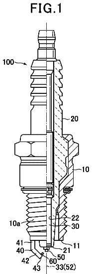
FIG. 1 shows a schematic view, partially in cross section, of a spark plug according to a present embodiment of the invention.
FIGS. 2A and 2B show an enlarged partially sectional elevation view and an enlarged right-side view of a front end part of a spark plug with no coating part formed on a ground electrode according to Comparative Example.
FIGS. 3A and 3B show an enlarged partially sectional elevation view and an enlarged right-side view of a front end part of a spark plug according to Experimental Example 1 of the present embodiment.
FIGS. 4A and 4B show an enlarged partially sectional elevation view and an enlarged right-side view of a front end part of a spark plug according to Experimental Example 2 of the present embodiment.
FIGS. 5A and 5B show an enlarged partially sectional elevation view and an enlarged right-side view of a front end part of a spark plug according to Experimental Example 3 of the present embodiment.
FIGS. 6A and 6B show an enlarged partially sectional elevation view and an enlarged right-side view of a front end part of a spark plug according to Experimental Example 4 of the present embodiment.
FIG. 7 shows a graph illustrating the amounts of wear of ground electrode base materials as used for Comparative Example and Experimental Examples in a first verification experiment.
FIGS. 8A and 8B show an enlarged partially sectional elevation view and an enlarged right-side view of a front end part of a spark plug according to a first application example of the present embodiment.
FIGS. 9A and 9B show an enlarged partially sectional elevation view and an enlarged right-side view of a front end part of a spark plug according to a second application example of the present embodiment.
FIGS. 10A and 10B show an enlarged partially sectional elevation view and an enlarged right-side view of a front end part of a spark plug according to Experimental Example 5 of the present embodiment.
FIGS. 11A and 11B show an enlarged partially sectional elevation view and an enlarged right-side view of a front end part of a spark plug according to Experimental Example 6 of the present embodiment.
FIGS. 12A and 12B show an enlarged partially sectional elevation view and an enlarged right-side view of a front end part of a spark plug according to Experimental Example 7 of the present embodiment.
FIGS. 13A and 13B show an enlarged partially sectional elevation view and an enlarged right-side view of a front end part of a spark plug according to Experimental Example 8 of the present embodiment.
FIGS. 14A and 14B show an enlarged partially sectional elevation view and an enlarged right-side view of a front end part of a spark plug according to a third application example of the present embodiment.
FIGS. 15A and 15B show an enlarged partially sectional elevation view and an enlarged right-side view of a front end part of a spark plug according to a fourth application example of the present invention.
FIGS. 16A and 16B show an enlarged partially sectional elevation view and an enlarged right-side view of a front end part of a spark plug according to Experimental Example 10 of the present embodiment.
FIG. 17 shows an enlarged partially sectional elevation view of a front end part of a spark plug according to a fifth application example of the present embodiment.
FIG. 18 shows an enlarged partially sectional elevation view of a front end part of a spark plug according to a sixth application example of the present invention.
FIGS. 19A and 19B show an enlarged partially sectional elevation view and an enlarged right-side view of a front end part of a spark plug according to Experimental Example 11 of the present embodiment.
FIGS. 20A and 20B show an enlarged partially sectional elevation view and an enlarged right-side view of a front end part of a spark plug according to Experimental Example 13 of the present embodiment.
FIG. 21 shows a graph illustrating the amounts of wear of ground electrode base materials as used for Comparative Example and Experimental Examples in a fourth verification experiment.
FIGS. 22A and 22B show an enlarged partially sectional elevation view and an enlarged right-side view of a front end part of a spark plug according to a seventh application example of the present embodiment.
FIGS. 23A and 23B show an enlarged partially sectional elevation view and an enlarged right-side view of a front end part of a spark plug according to an eighth application example of the present invention.
FIG. 24 shows an enlarged partially sectional elevation view of a front end part of a modification example of the spark plug as used in the fourth verification experiment.
FIG. 25 shows an enlarged right-side view of a front end part of a spark plug with a coating part formed on a ground electrode in a fifth verification experiment.
FIG. 26 shows a graph illustrating the amount of wear of ground electrode base material, with respect to different thicknesses of the coating part, as used in the fifth verification experiment.
FIG. 27 shows an enlarged partially sectional elevation view of a front end part of a spark plug according to Experimental Example 14 of the present embodiment as used in a sixth verification experiment.
FIG. 28 shows an enlarged plan view of the front end part of the spark plug according to Experimental Example 14 of the present embodiment.
FIG. 29 shows a perspective view of the spark plug as viewed in a direction of arrow Z of FIG. 27 .
FIG. 30 shows a schematic view explaining a definition example of a coating part on a ground electrode base material in the spark plug according to the present embodiment.
FIG. 31 shows an enlarged right-side view of a front end part of a spark plug with a coating part formed on a ground electrode according to Experimental Example 15 of the present embodiment.
FIG. 32 shows an enlarged right-side view of a front end part of a spark plug with a coating part formed on a ground electrode according to Experimental Example 16 of the present embodiment.
FIG. 33 shows an enlarged right-side view of a front end part of a spark plug with a coating part formed on a ground electrode according to Experimental Example 17 of the present embodiment.
FIG. 34 shows an enlarged right-side view of a front end part of a spark plug with a coating part formed on a ground electrode according to Experimental Example 18 of the present embodiment.
FIG. 35 shows a graph illustrating the amount of wear of ground electrode base material, with respect to different widths of the coating part, as texted by Experimental Examples 15 to 18.
FIG. 36 shows an enlarged partially sectional elevation view of a front end part of a spark plug with a coating part formed on a ground electrode according to Experimental Example 19 of the present embodiment.
FIG. 37 shows an enlarged plan view of the front end part of the spark plug with the coating part formed on the ground electrode according to Experimental Example 19 of the present embodiment.
FIG. 38 shows an enlarged right-side view of a front end part of a spark plug with a coating part formed on a ground electrode according to Experimental Example 20 of the present embodiment.
FIG. 39 shows an enlarged plan view of the front end part of the spark plug with the coating part formed on the ground electrode according to Experimental Example 20 of the present embodiment.
FIGS. 40A and 40B show schematic views explaining the positional relationship between a coating part and a front end of an electrode top in Experimental Examples 20 to 24.
FIG. 41 shows an enlarged right-side view of a front end part of a spark plug with a coating part formed on a ground electrode according to Experimental Example 20 of the present embodiment.
FIG. 42 shows an enlarged right-side view of a front end part of a spark plug with a coating part formed on a ground electrode according to Experimental Example 21 of the present embodiment.
FIG. 43 shows an enlarged right-side view of a front end part of a spark plug with a coating part formed on a ground electrode according to Experimental Example 22 of the present embodiment.
FIG. 44 shows an enlarged right-side view of a front end part of a spark plug with a coating part formed on a ground electrode according to Experimental Example 23 of the present embodiment.
FIG. 45 shows an enlarged right-side view of a front end part of a spark plug with a coating part formed on a ground electrode according to Experimental Example 25 of the present embodiment.
FIG. 46 shows a graph illustrating the amount of volumetric wear of ground electrode base material, with respect to the displacement, as tested by Experimental Examples 20 to 24.
FIG. 47 shows an enlarged plan view of a front end part of a first modification example of the spark plug as used in the sixth verification experiment.
FIG. 48 shows an enlarged plan view of a front end part of a second modification example of the spark plug as used in the sixth verification experiment.
FIG. 49 shows an enlarged plan view of a front end part of a third modification example of the spark plug as used in the sixth verification experiment.
FIG. 50 shows an enlarged plan view of a front end part of a fourth modification example of the spark plug as used in the sixth verification experiment.
FIG. 51 shows an enlarged plan view of a front end part of a fifth modification example of the spark plug as used in the sixth verification experiment.
FIG. 52 shows an enlarged plan view of a front end part of a sixth modification example of the spark plug as used in the sixth verification experiment.
Description of embodiments
Hereinafter, a spark plug 100 as a spark plug according to the present embodiment of the invention will be described below with reference to the drawings. FIG. 1 shows a schematic view, partially in cross section, of the spark plug according to the present embodiment. In FIG. 1 , a longitudinal center axis of the spark plug 100 is indicated as an axis CL by an alternate long and short dash line. The right side of FIG. 1 with respect to the axis CL shows an outside elevation view of the spark plug 100 , whereas the left side of FIG. 1 with respect to the axis CL shows a cross-sectional view of the spark plug 100 taken along the center axis of the spark plug 100 . In the following description, the term “front” refers to a bottom side of FIG. 1 in the direction of the axis CL of the spark plug 100 , i.e., a side of the spark plug 100 exposed to a combustion chamber; and the term “rear” refers to a top side of FIG. 1 in the direction of the axis CL of the spark plug 100 , i.e., a plug attachment side of the spark plug 100 . The spark plug 100 has an insulator 10 , a center electrode 20 , a ground electrode 30 , a terminal electrode 40 and a metal shell 50 .
The insulator 10 is formed in a cylindrical shape by firing a ceramic material such as alumina. An axial hole 12 is made through the center of the insulator 10 in the direction of the axis CL such that the center electrode 20 and the terminal electrode 20 are placed in the axial hole 12 . The insulator 10 includes: a middle body portion 19 located at a middle position thereof in the direction of the axis CL and having the largest outer diameter throughout the insulator 10 ; a rear body portion 19 located rearward of the middle body portion 18 so as to provide insulation between the terminal electrode 50 and the metal shell 40 ; a front body portion 17 located frontward of the middle body portion 18 and having an outer diameter smaller than that of the rear body portion 19 ; a leg portion 13 located frontward of the front body portion 17 and having an outer diameter smaller than that of the front body portion 17 and gradually decreasing toward the center electrode 20 ; and a diameter-decreasing portion 15 located between the front body portion 17 and the leg portion 13 and having an outer diameter gradually decreasing toward the front so as to connect the front body portion 17 and the leg portion 13 to each other.
The center electrode 20 is inserted in the axial hole 12 . The center electrode 20 has a rod shape and includes: a bottomed cylindrical-shaped center electrode base material 21 ; and a core 25 having higher thermal conductivity than that of the center electrode base material 21 and fitted in the center electrode base material 21 . In the present embodiment, the center electrode base material 21 is formed of a nickel alloy containing nickel (Ni) as a main component; and the core 25 is formed of copper or an alloy containing copper as a main component. An electrode tip 22 of noble metal or noble metal alloy such as iridium alloy is joined to a front end of the center electrode base material 21 (see FIGS. 2A and 2B and FIGS. 3A and 3B ). The electrode tip 22 is generally formed in a cylindrical column shape, but can alternatively be formed in any other shape such as rectangular column shape. It is noted that, although the electrode tip 22 is provided in the same manner as above in the drawings other than FIGS. 2A and 2B and FIGS. 3A and 3B , the electrode tip 22 may be omitted from illustration for simplicity purposes. The center electrode 20 is held by the insulator 10 in the axial hole 12 with the electrode tip 22 protruding and exposed outside from the axial hole 12 (insulator 10 ). Further, the center electrode 20 is electrically connected to the terminal electrode 40 via a ceramic resistor 3 and a seal member 4 within the axial hole 12 . In the following description, the front end and front end face of the electrode tip 22 are sometimes comprehensively referred to as the front end and front end face of the center electrode 20 .
The ground electrode 30 is made of a high corrosion-resistant metal material. By way of example, a nickel alloy is used as the base material of the ground electrode 30 in the present embodiment. A fixed end portion (basal end portion) 31 of the ground electrode 30 is fixed by welding to a front end face 57 of the metal shell 50 . The ground electrode 30 extends from the fixed end portion 31 , and is bent or curved toward the center electrode 20 such that a free end portion (distal end portion) 32 of the ground electrode 30 is located at a predetermined gap apart from the front end face of the center electrode 20 . The free end portion 32 of the ground electrode 30 includes a center electrode-facing site 30 b opposed to and facing the center electrode 20 . The predetermined gap between the free end portion 32 of the ground electrode 30 and the front end 22 a (front end face) of the center electrode 20 serves as a spark gap SG for spark discharge.
The terminal electrode 40 is inserted in a rear side of the axial hole 12 , with a rear end portion of the terminal electrode 40 protruding and exposed outside from a rear end of the insulator 10 . A high-voltage cable (not shown) is attached to the terminal electrode 40 via a plug cap (not shown) so as to apply therethrough a high voltage for spark discharge.
The metal shell 50 is cylindrical-shaped so as to circumferentially surround and hold a region of the insulator 10 extending from a point on the rear body portion 18 to over the leg portion 13 . In the present embodiment, the metal shell 50 is made of low carbon steel and is entirely treated by plating such as nickel plating or zinc plating. The metal shell 50 includes a tool engagement portion 51 , a mounting thread portion 52 , a crimp portion 53 and a seal portion 54 . The crimp portion 53 , the tool engagement portion 51 , the seal portion 54 and the mounting thread portion 52 are arranged in this order from the rear toward the front. The tool engagement portion 51 is engageable with a tool for mounting the spark plug 100 to a cylinder head 150 of an internal combustion engine. The mounting thread portion 51 is formed with a screw thread for screwing into a mounting thread hole 151 of the cylinder head 150 .
A radially inward protruding portion 60 is formed on an inner diameter side of the mounting thread portion 52 at a position opposed to the diameter decreasing portion 15 of the ceramic insulator 10 and to the rear end side of the leg portion 13 . A packing 8 as an annular seal member is arranged between the protruding portion 60 and the diameter decreasing portion 15 of the insulator 10 and is held contact with the protruding portion 60 and the diameter decreasing portion 15 so as to provide seal between the insulator 10 and the metal shell 50 . A cold-rolled steel plate etc. can be used as the packing 8 .
The crimp portion 53 is formed with a small thickness on a rear end side of the metal shell 50 such that the insulator 10 is held in the metal shell 50 by means of the crimp portion 53 . More specifically, the crimp portion 53 is bent inwardly and pressed toward the front during manufacturing of the spark plug 100 . By such bending and pressing, the insulator 10 is held integrally in the metal shell 53 with the front end of the center electrode 20 protruding from the front end of the metal shell 50 . The seal portion 54 is formed in a collar shape at the bottom of the mounting thread portion 51 . An annular gasket 15 , which is formed by bending a plate material, is arranged between the seal portion 54 and the cylinder head. The thus-manufactured spark plug 100 is mounted in the mounting thread hole 151 of the cylinder head 150 via the metal shell 50 .
In the present embodiment, the spark plug 100 has a coating part 80 formed of noble metal or noble metal alloy on the base material of the ground electrode 30 so as to suppress or prevent wear of the base material of the ground electrode 30 .
The arrangement configuration and thickness of the coating part 80 on the ground electrode 30 will be verified below. Although the arrangement configuration and thickness of the coating part 80 are varied in the respective verifications, the following explanations are given to differences of the respective verifications by using common reference numerals and avoiding complicated reference numerals. First Verification Experiment
The first verification experiment is intended to verify the arrangement configuration of the coating part 80 on the ground electrode 30 from the viewpoint of suppressing or preventing wear of the base material of the ground electrode 30 . FIGS. 2A and 2B show an enlarged partially sectional elevation view and an enlarged right-side view of a front end part of a spark plug with no coating part formed on a ground electrode according to Comparative Example. FIGS. 3A and 3B show an enlarged partially sectional elevation view and an enlarged right-side view of the front end part of the spark plug according to Experimental Example 1 of the present embodiment. FIGS. 4A and 4B show an enlarged partially sectional elevation view and an enlarged right-side view of the front end part of the spark plug according to Experimental Example 2 of the present embodiment. FIGS. 5A and 5B show an enlarged partially sectional elevation view and an enlarged right-side view of the front end part of the spark plug according to Experimental Example 3 of the present embodiment. FIGS. 6A and 6B show an enlarged partially sectional elevation view and an enlarged right-side view of the front end part of the spark plug according to Experimental Example 4 of the present embodiment.
The basic structure of the ground electrode 30 used in the first verification experiment is the same as that of Comparative Example shown in FIGS. 2A and 2B . The ground electrode 30 has: an inner surface 30 c formed facing the center electrode 20 and the insulator 10 ; and an outer surface 30 d formed as all surface except the inner surface 30 c . The outer surface 30 d can be defined as a surface connecting one end (side) to the other end (side) of the inner surface 30 c in the width direction. In the case where the ground electrode 30 is rectangular in cross section, both of an outer surface 30 d corresponding to a back surface opposite the inner surface 30 c and a side surface 30 e connecting the inner surface 30 c and the outer surface 30 d are included in the outer surface 30 d . In the present specification, the outer surface 30 d and the side surface 30 e may be thus collectively referred to as the outer surface 30 d in contrast to the inner surface 30 c . In the case where the ground electrode 30 has a curved surface area connecting one end (side) to the other end (side) of the inner surface 30 c in the width direction or in the case where the ground electrode 30 is circular in cross section, the outer surface 30 refers to the curved surface area or lower curved surface area of the ground electrode 30 .
In Experimental Example 1, the coating part 80 is formed on the ground electrode 30 of the spark plug 100 so as to cover a region of the inner surface 30 c from an insulator-facing site 30 a , which is opposed to and facing a front end portion 10 a of the insulator 10 , to the center electrode-facing site 30 b . In Experimental Example 2, the coating part 80 is formed on the ground electrode 30 of the spark plug 100 so as to cover the whole of the inner surface 30 c from the fixed end (fixed end portion) 31 to the edge of the free end portion 32 . In Experimental Example 3, the coating part 80 is formed on the ground electrode 30 of the spark plug 100 so as to cover the surface of the ground electrode 30 from the fixed end (fixed end portion) 31 to the edge of the free end portion 32 , except the region of the outer surface 30 d corresponding to the back surface opposite the inner surface 30 c . In Experimental Example 4, the coating part 80 is formed on the ground electrode 30 of the spark plug 100 so as to cover the whole surface of the ground electrode 30 except an end face of the free end portion 32 . As a modification example, the coating part 80 may also be formed on the end face of the free end portion 32 .
It is feasible to form the coating part 80 on the ground electrode 30 by various techniques, such as surface coating treatment by electroless plating, joining of a coating material by laser welding, or formation of a coating film by PVD (physical vapor deposition) or CVD (chemical vapor deposition) etc.
For the first verification experiment, spark plug samples of Experimental Examples 1 to 4 were each prepared by forming the coating part 30 on the ground electrode 30 as explained above. In each sample, the metal shell was of M12HEX14 type (i.e. the diameter of the mounting thread portion was 12 mm; and the size (diagonal dimension) of the hexagonal portion was 14 mm); the electrode tip of iridium (Jr) with a diameter of 0.6 mm was joined to the front end of the center electrode; the spark gap SG was set to 1.1 mm; the ground electrode 30 was rectangular in shape with a width of 2.7 mm and a thickness of 1.3 mm; and the coating part 80 was formed of platinum (Pt) with a thickness of 0.4 mm on the ground electrode 30 . A bench test was performed on each of the spark plug samples in a velocity field of 10 m/s airflow through the spark gap SG under the conditions of: an ignition frequency of 30 Hz; a combustion chamber pressure of 0.4 MPa; an atmosphere of nitrogen; and an endurance time of 200 hours. Then, the volume of wear of the base material of the ground electrode 30 caused during the test was measured and evaluated. In view of the flow of air-fuel mixture in the combustion chamber at spark ignition timing, the velocity field was set to allow the airflow in a direction from the center electrode 20 to the ground electrode 30 . Herein, the outer dimensions of the ground electrode 30 with the coating part 80 were measured by X-ray CT scanning; the volume of the ground electrode 30 was calculated from the measured outer dimensions; and the volume of wear was determined by subtracting the volume of the ground electrode remaining after the test from the initial volume of the ground electrode.
The evaluation results are shown in TABLE 1 and FIG. 7 . FIG. 7 shows a graph illustrating the amounts of wear of the ground electrode base materials as used for Comparative Example and Experimental Examples in the first verification experiment.
TABLE-US-00001 TABLE 1 Volume (mm.sup.3) of Wear of Ground Electrode Base Material Endurance Comparative Experimental Experimental Experimental Experimental Time (h) Example 1 Example 1 Example 2 Example 3 Example 4 200 3.4 0.7 0.5 0.2 0.2
In the sample of Comparative Example where no coating part 80 was formed, the volume of wear of the ground electrode base material was 3.4 mm.sup.3. On the other hand, the volume of wear of the ground electrode base material was less than 1.0 mm.sup.3 in each of the samples of Experimental Examples 1 to 4 where the coating part 80 was formed. In each of the samples of Experimental Examples 1 and 2, the volume of wear of the ground electrode base material was reduced to a level acceptable as technically effective even though the coating part 80 was formed only on the inner surface 30 c of the ground electrode 30 . The samples of Experimental Examples 1 and 2 were different in that the coating part 80 was formed on the region of the inner surface 30 of the ground electrode 30 from the insulator-facing site 30 a to the center electrode-facing site 30 b (Experimental Example 1) or formed on the whole of the inner surface 30 c of the ground electrode 30 (Experimental Example 2). However, there was no large difference in the wear volume of the ground electrode base material between Experimental Examples 1 and 2. Since the coating part 40 is formed of corrosion-resistant noble metal or noble metal alloy, a reduction of the amount of noble metal material used for the coating part 40 leads to a cost reduction. It can be concluded that Experimental Example 1 can achieve a balance in terms of suppression of wear of the base material and cost reduction. It has been shown by the above results of the first verification experiment that, as long as the coating part 80 is formed on at least the region of the inner surface of the ground electrode 30 from the insulator-facing site 30 a to the center electrode-facing site 30 b , it is possible to suppress or prevent wear of the ground electrode base material at the area to which sparks tend to be blown. Further, it is known that a bent or curved portion of the ground electrode 30 is susceptible to wear by sparks. In order to suppress or prevent the ground electrode from being broken from its basal end portion due to wear of the bent or curved portion of the ground electrode base material, it is preferable that the coating part 80 is formed on at least the inner surface 30 c of the bent or curved portion of the ground electrode 30 . It is also preferable that the coating part 80 is formed on the center electrode-facing site 30 b which is most susceptible to wear by sparks. For these reasons, it is preferable that the coating part 80 is formed on at least the region of the inner surface of the ground electrode 30 from the insulator-facing site 30 a to the center electrode-facing site 30 b.
Application examples of the spark plug 100 other than those used as Experimental Examples 1 to 4 in the first verification experiment are shown in FIGS. 8 to 10 . FIGS. 8A and 8B show an enlarged partially sectional elevation view and an enlarged right-side view of the front end part of the spark plug according to the first application example of the present embodiment. FIGS. 9A and 9B show an enlarged partially sectional elevation view and an enlarged right-side view of the front end part of the spark plug according to the second application example of the present embodiment.
The arrangement configuration of the coating part 80 in the first application example is different from that in Experiment Example 1, in that the coating part 80 is not formed on a lower-side region (outer surface 30 d side region) of the side surface 30 e . It is apparent from the results of the first verification experiment that, even when the coating part 80 is not formed on the side surface 30 e , it is possible to suppress wear of the ground electrode base material caused by exposure to blowing of sparks. Thus, the arrangement configuration in which the coating part 80 is not formed on the region of the side surface 30 e from the lower side (i.e. the intersection of the outer surface 30 d and the side surface 30 c ) to an arbitrary point is included in the present embodiment.
The second application example is the same as the first application example, except that the ground electrode 30 has a cylindrical column shape in the second application example. In the case where the ground electrode 30 is circular in cross section, the inner surface 30 c and the outer surface 30 d can be defined as mentioned above. More specifically, the inner surface 30 c refers to a surface closer to the center electrode than an imaginary line 30 f that passes through a geometrical center 30 g of gravity of the end face of the ground electrode 30 when visually observed from the side of the free end portion 32 and extends through the outer surface 30 d in parallel with the inner surface 30 c ; and the outer surface 30 d refers to a surface opposite the inner surface 30 c . The coating part 80 is formed on the above-defined inner surface 30 c . For increase in strength, the coating part 80 may be formed of a platinum alloy instead of 100% platinum (Pt). The term “thickness” may refer to a thickness of the coating part 80 at a given position or an average thickness of the coating part 80 . Second Verification Experiment
It has been verified by the first verification experiment that it is possible to reduce or prevent wear of the ground electrode base material by forming the coating part 80 of noble metal or noble metal alloy on the ground electrode. On the other hand, it is known that noble metal such as platinum (Pt) or noble metal alloy shows a catalytic activity with increase in temperature and thereby ignites air-fuel mixture without spark ignition. There thus arises a problem that the formation of the coating part 80 on the ground electrode 80 may cause unintended self-ignition (abnormal combustion), which interferes with combustion control. Hence, the second verification experiment is intended to verify the arrangement configuration of the coating part 80 on the ground electrode 30 from the viewpoint of suppressing or preventing the occurrence of abnormal combustion while suppressing or preventing wear of the base material of the ground electrode 30 .
FIGS. 10A and 10B show an enlarged partially sectional elevation view and an enlarged right-side view of the front end part of the spark plug according to Experimental Example 5 of the present embodiment. FIGS. 11A and 11B show an enlarged partially sectional elevation view and an enlarged right-side view of the front end part of the spark plug according to Experimental Example 6 of the present embodiment. FIGS. 12A and 12B show an enlarged partially sectional elevation view and an enlarged right-side view of the front end part of the spark plug according to Experimental Example 7 of the present embodiment. FIGS. 13A and 13B show an enlarged partially sectional elevation view and an enlarged right-side view of the front end part of the spark plug according to Experimental Example 8 of the present embodiment.
The description continues in the full USPTO document.
 Lapsed, fee not paid22 drawings