Technical field
This invention relates to solution synthesis of mixed metal borohydrides. These compounds can be used to store and release hydrogen for many different applications, including fuel cells.
Background
The demand for energy storage systems that are compact, lightweight, safe and powerful is skyrocketing with the worldwide proliferation of portable electronic devices, including notebook and tablet computers, PDAs, camcorders, digital cameras, mobile phones and increase electronics usage by the military.
Batteries provide a limited amount of energy and have shown slow improvement. Although Moore's Law has computing capability doubling in capacity every two-three years or so, increases in battery capacity have not kept pace. As a result, a “Power Gap” exists between energy demand and the energy available in today's rechargeable batteries. With current battery technology at risk of not keeping pace with product evolution and new technology adoption, military decision makers and consumer electronic manufacturers are turning to alternative energy sources to address the Power Gap, and provide clean renewable power sources which enable “always on” capability at significantly reduced weight. Fuel cells are one of the most promising technologies that can bridge the Power Gap and provide portable products with a significant increase in runtime and greater convenience of use.
One type of fuel cell is proton exchange membrane (PEM) fuel cells; their distinguishing features include lower temperature/pressure ranges (50 to 100° C.) and a special polymer electrolyte membrane. The fuel in a PEM fuel cell is typically hydrogen; in order to utilize hydrogen for a consumer electronic device fuel cell, it needs to be delivered or supplied as part of a solid material that can store it.
The key limiting factor in the widespread adoption of PEM fuel cell based power systems is hydrogen fuel storage. Realization of a viable hydrogen storage solution will have a profound impact on how military and civilian consumers will power portable devices, since batteries simply cannot match demands for runtime, energy density and reliability. A viable hydrogen storage system will enable direct hydrogen fuel cell based power systems, which are considered to be the best alternative to compete with lithium ion battery technologies, for portable applications.
In order to be competitive with lithium ion battery technology, a hydrogen storage cartridge must achieve volumetric energy densities on the order of 1200 Wh/L. The amount of fuel required in the hydrogen storage cartridge such that 1200 Wh/L are provided depends on the fuel material density and gravimetric hydrogen density. Because hydrogen has poor energy content per volume (0.01 kJ/L at standard temperature and pressure (STP) and 8.4 MJ/L for liquid hydrogen vs. 32 MJ/L for petroleum), physical transport and storage as a gas or liquid is impractical. Additionally, the compression process to achieve the pressures necessary to reach a high density is energy-intensive and doesn't solve the hazard issue. Also, the densities of compressed H.sub.2 are still below those required to reach practical fuel storage goals.
Physical means to store hydrogen include complex hydrides such as metal alanates, amides, and borohydrides. Complex hydrides are salts consisting of a metal cation and an anion containing hydride such as tetrahydroborate [BH.sub.4].sup.− and tetrahydroaluminate [AlH.sub.4].sup.−. The hydrogen in complex hydrides can be released hydrolytically, which is essentially an irreversible process, and by heating or reduction of vessel pressure, which are reversible processes if a pressure increase or temperature decrease also leads to readsorption of hydrogen. For hydrogen storage, Group 1 and 2 salts of alanates [AlH.sub.4].sup.−, amides [NH.sub.2].sup.− and borohydrides [BH.sub.4].sup.− have been studied extensively and have high hydrogen gravimetric densities (Jain, et. al., J. Alloys & Compounds 2010, 03, 303-339; Orimo, et. al., (“Orimo”) Chem. Rev. 2007, 107, 4111-4132; Schüth, F. Eur. Phys. J. Special Topics 2009 176, 155-166; Eberle, et. al., Angew. Chem. Int. Ed. 2009, 48, 6608-6630.). However, high thermal stabilities and kinetics barriers to dehydrogenation and/or rehydrogenation in the solid state have thus far prevented complex hydrides from becoming practical hydrogen storage solutions.
Several methods have been investigated in an attempt to improve the thermodynamic properties of complex hydrides, such as formation of nanocomposites and through nanocatalysis (Orimo; Chen, et. al., Materials Today 2008, 11(12), 36-43.). The composite of lithium borohydride with magnesium hydride showed reduced enthalpy of decomposition from −67 to −42 kJ mol.sup.−1 with reversibility (Newhouse, et. al., J. Phys. Chem . C 2010, 114, 5224-5232; Vajo, Jet. al., J. Phys. Chem . B 2005, 109, 3719-3722.; Bösenberg, et. al., Acta Mater. 2007, 55, 39513958.). Another approach, doping or catalyzing a complex hydride with another material, was demonstrated using sodium alanate (NaA1H.sub.4) and select titanium compounds. Doped sodium alanate was shown to release hydrogen reversibly at temperatures as low as 100° C. Complex hydrides are an emerging and promising field of research for hydrogen storage. However, thermodynamics and kinetics remain challenging issues.
A recent approach for thermodynamic tuning is the investigation of alkali and alkaline earth metal mixed cation alanates and borohydrides (Graetz, J. Chem. Soc. Rev. 2009, 38, 73-82.). These types of compounds could include new compositions (inorganic ate complexes), reactive hydride composites (i.e., react during heating in the solid state and release hydrogen at temperatures below that of the constituent borohydrides), or react on heating as a simple mixture of constituent borohydrides (in other words, not be useful for the production of hydrogen gas). Mixed metal borohydride materials have been studied by many research groups in the past five to ten years.
The synthetic methods used to prepare these materials can be divided into three groups: solution synthesis, solid-state mechanochemical synthesis such as ball-milling, and high temperature/pressure synthesis (Hagemann, H.; Ĉerny, R. Dalton Trans. 2010, 39, 6006-6012.). The most prevalent method currently being used for the synthesis of the reported mixed metal borohydride ate complexes is ball-milling. However, a problem with mechanochemical synthesis, particularly for the synthesis of highly reactive materials, is the difficulty preparing pure, halogen-free samples of the expected products. Purification after mechanochemical synthesis is labor-intensive and can be difficult. High temperature/pressure synthesis is neither convenient nor scalable in a practical sense, since material impurities can have a profound impact on dehydrogenation temperature and material stability.
The objectives of the present invention include providing new mixed metal borohydride complexes that are suitable for solid hydrogen storage at practical operating conditions. The complexes are preferably stable under ambient conditions, including ambient air and temperature conditions. The objectives include complexes that can release hydrogen within a temperature range of 100° C. to 400° C. and more preferably within a range of 100° C. to 250° C. The objectives also include having a hydrogen storage material that has shelf stability. The objectives also include creating complexes with lower reaction temperatures and/or greater hydrogen storage capacities than any of the parent compounds.
According to another objective of the invention, there is provided a hydrogen generating apparatus that can be in any number of different embodiments. For example, the hydrogen generating apparatus can include a housing; a pellet strip including a flexible carrier and a plurality of pellets disposed on the carrier, each pellet including a mixed metal borohydride that will release hydrogen gas when heated; an ignition system comprising a heater; and a feed system configured to feed the pellet strip to sequentially position one or more pellets in proximity to the heater such that the heater is capable of heating the proximal pellet to release hydrogen gas. Embodiments can include one or more of the following features: the pellet strip is wound on a reel disposed within the housing; the hydrogen generator includes a plurality of pellet strips; the plurality of pellet strips can be disposed on a single reel, or at least one pellet strip can be disposed on each of a plurality of reels; the pellet strip is in a folded configuration, preferably in a Z-fold pattern; the pellets disposed on one section of the carrier are nested between the pellets disposed on another section of the carrier; the hydrogen generator includes a plurality of pellet strips; the carrier is in the form of a strip with surfaces on opposite sides thereof; the pellets can be disposed on one of the surfaces of the carrier, or the pellets can be disposed on both surfaces of the carrier; the pellets can be disposed in a linear array along the carrier; the pellets can be disposed in a plurality of linear arrays along the carrier; the pellet strip is disposed in a storage compartment within the housing; the hydrogen generator comprises a plurality of storage compartments within the housing, each configured to contain at least one pellet strip; each compartment can have a feed system configured to feed the at least one pellet strip therein; the storage compartment is defined by a moveable wall; the moveable wall can be moveable to reduce the size of the storage compartment as the carrier and pellets are fed by the feed system; the moveable wall can separate the storage compartment from a waste compartment within the housing; a portion of the feed system can be moveable together with the moveable wall; the feed system includes a sprocket that cooperates with the pellets disposed on the carrier; the sprocket can be an indexing sprocket; the feed system can include a ratchet configured to allow the carrier to be advanced in only one direction; the feed system can include a bellows that engages an escapement to rotate the sprocket; the ignition system includes more than one heater; the pellet strip is contained in a user-replaceable container; each pellet includes at least one mixed metal borohydride; and the pellet includes an ignition material.
In another objective of the invention, there is provided another embodiment of a hydrogen generator. The hydrogen generator includes a sealable housing having an openable member and a hydrogen outlet; a plurality of fuel units removably disposed within the housing, each fuel unit including a casing containing a stack of pellets, and each pellet containing at least one mixed metal borohydride capable of producing hydrogen gas when heated; and a heating system for selectively heating one or more pellets to produce hydrogen gas. The heating system includes a plurality of heating elements disposed on an inside surface of the housing, each heating element in contact with a portion of the fuel unit casing that is in contact with one or more of the pellets contained therein. Heat selectively produced by one of the heating elements can be conducted through the corresponding portion of the fuel unit casing to heat one or more of the pellets. Embodiments can include one or more of the following features: the heating system can further include a plurality of heat concentrators, each heat concentrator in contact with and configured to conduct heat to, a portion of a pellet; the heat concentrators can be disposed on external surfaces of the pellets; the heat concentrators can be at least partially disposed within the pellets; a single heat concentrator can be in contact with a single pellet; a single heat concentrator can be in contact with more than one pellet; more than one heat concentrator can be in contact with a single pellet; the fuel unit includes thermal insulation between adjacent pellets; each fuel unit casing includes a metal such as aluminum or stainless steel; each fuel unit includes a hydrogen exit; the hydrogen generator can include one or more hydrogen flow paths from the hydrogen exits to the hydrogen outlet; one or more filters can be disposed within a portion of the one or more hydrogen flow paths; the housing includes thermal insulation; and the hydrogen generator includes at least a portion of a control system for controlling the selective heating of the pellets; the control system can be configured to monitor at least one of temperature and pressure and selectively heat one or more pellets based at least in part on at least one of the temperature and pressure.
In another objective of the invention, there is provided another embodiment of a hydrogen generator, the hydrogen generator including a cartridge, a compartment configured to removably contain the cartridge, and an ignition system. The cartridge includes a sealed casing with a side wall, a base wall, and a lid; a plurality of pellets, each comprising at least one mixed metal borohydride capable of producing hydrogen gas when heated; a heat concentrator in direct contact with the casing and capable of conducting heat from the casing to the at least one reactant; a hydrogen outlet valve in the casing; and a hydrogen flow path from each fuel pellet to the hydrogen outlet valve. The compartment includes a housing with a side wall and a lid; a hydrogen outlet through the housing; a cavity within the housing within which the cartridge can be disposed; and a plurality of heating elements disposed on an inside surface of the housing, such that each heating element is in contact with an outer surface of the cartridge casing and aligned with a heat concentrator when the cartridge is disposed within the cavity. The ignition system includes the heat concentrators, the heating elements, and circuitry for conducting an electric current to the heating elements, such that the electrical current can be applied selectively to one or more heating elements for generating heat to selectively heat one or more pellets to initiate a reaction to produce hydrogen gas. Embodiments can include one or more of the following features: the cartridge has a cylindrical shape; the cartridge has a prismatic shape; the cartridge and the compartment cooperate such that the cartridge can be inserted into the compartment only such that the heating elements and the heat concentrators are properly aligned; the pellets are arranged in multiple layers, each layer having a single pellet; the pellets are arranged in multiple layers, each layer containing more than one pellet; the pellets are arranged in a single layer; the heat concentrators are disposed on pellet surfaces; the heat concentrators are partially disposed within the pellets; each heat concentrator has a cartridge casing contact portion that extends beyond the pellet; each heat concentrator comprise aluminum; each heat concentrator comprises a layer of pyrolictic carbon in contact with the pellet; the heat concentrators are in pressure contact with the inside surface of the casing; a thermally insulating material is disposed between at least portions of adjacent pellets; a layer of the insulating material can separate layers of the pellets; pellet surfaces can be coated with a layer of the insulating material; the portion of the cartridge casing that makes contact with the heating element comprises stainless steel or aluminum; the housing comprises a material with low electrical and thermal conductivity; the heating elements are disposed on an inside surface of at least one of the side wall, the lid and the door of the housing; the heating elements make pressure contact with the outer surface of the cartridge casing when the cartridge is disposed within the compartment; the cartridge can include means for maintaining contact between the heat concentrators and the solid compositions and/or maintaining alignment between the heat concentrators and the heating elements as the heat generator is being used; the hydrogen flow path comprises a channel extending through all layers of pellets; the hydrogen flow path can include a central channel; the hydrogen flow path can comprise more than one channel; at least one filter is disposed in the hydrogen flow path; the cartridge comprises a foil seal over the hydrogen outlet valve prior to insertion of the cartridge into the compartment; the foil seal can be broken upon insertion of the cartridge into the compartment; and the pellets further comprise an ignition material, preferably at least one material selected from the group of iron powder plus KC1O4, TiH2 plus KC1O4, Mn02 plus LiA1H4, Ni plus Al, Zr plus PbCrO.sub.4, Fe.sub.2O.sub.3 plus Al, and LiA1H.sub.4 plus NH.sub.4C1.
In another objective of the invention, there is provided another embodiment of a hydrogen generator including a cartridge including a sealed casing and a plurality of pellets stacked within the casing, each pellet containing at least one mixed metal borohydride capable of producing hydrogen gas when heated; a compartment including a housing, a hydrogen outlet through the housing, and a cavity within the housing within which the cartridge can be removably disposed; and an induction heating system. The induction heating system includes a plurality of secondary coils within the cartridge casing, with each secondary coil in contact with one or more of the pellets. The induction heating system also includes at least one primary coil within the compartment housing. The induction heating system is configured to receive an electric current from a power source, provide an electromagnetic field from a flow of the current in the at least one primary coil, induce an electric current in the at least one secondary coil, and provide heat from a flow of the induced electric current; thereby heating the pellets. Embodiments can include one or more of the following features: the cartridge has a cylindrical shape; the cartridge has a prismatic shape; the pellets are arranged in multiple layers, each layer having a single pellet; each pellet is in contact with a secondary coil; each pellet can be in contact with a separate secondary coil; more than one pellet can be in contact with the same secondary coil; the at least one secondary coil is in contact with a pellet surface; the at least one secondary coil is disposed at least partially within a pellet; the induction heating system includes a moveable primary coil; the induction heating system includes a plurality of primary coils; the primary coils can be adjacent to, on or at least partially recessed in an inner surface of the compartment housing; a thermally insulating material is disposed between adjacent pellets; the cartridge can include means for maintaining contact between the solid compositions and the secondary coils; the cartridge can include means for maintaining alignment between the secondary coils and the primary coils as the heat generator is being used; the hydrogen flow path comprises a channel extending through and/or around the pellets; the hydrogen flow path can include a central channel; the hydrogen flow path can comprise more than one channel; at least one filter is disposed in the hydrogen flow path; the cartridge comprises a foil seal over the hydrogen outlet valve prior to insertion of the cartridge into the compartment; the foil seal can be broken upon insertion of the cartridge into the compartment; and the pellets further comprise an ignition material, preferably at least one material selected from the group of iron powder plus KC1O.sub.4, TiH.sub.2 plus KC1O.sub.4, MnO.sub.2 plus LiA1H.sub.4, Ni plus Al, Zr plus PbCrO.sub.4, Fe.sub.2O.sub.3 plus Al, and LiA1H.sub.4 plus NH.sub.4C1.
In yet another objective of the invention, there is provided a fuel cell system including a fuel cell with an anode, a cathode, and an electrolyte that that is used with any of the hydrogen generators as described herein. Hydrogen gas from a hydrogen generator is supplied to the anode of the fuel cell. Embodiments can include one or more of the following features: the fuel cell cathode is supplied with oxygen. the fuel cell electrolyte separates the anode and the cathode. the fuel cell system further includes a control system configured to control an ignition system and a feed system based on at least one of a pressure within the fuel cell system, an electrical characteristic of the fuel cell system, or an electrical characteristic of an electronic device in electrical communication with the fuel cell system; the control system can include at least one of a microprocessor, a micro controller; digital circuitry, analog circuitry, hybrid digital and analog circuitry; a switching device; a capacitor, and sensing instrumentation. the fuel cells are “stacked,” or placed in series or parallel circuits, to increase the voltage and current output to meet an application's power generation requirements. the fuel cell system includes a control system for controlling the selective heating of the pellets; a portion of the control system can be disposed within the hydrogen generator; a portion of the control system can be disposed outside the hydrogen generator. the ignition system is configured to monitor at least one of temperature and pressure and selectively heat one or more pellets to provide hydrogen as needed by the fuel cell stack. a portion of the ignition system is in the fuel cell system outside the hydrogen generator.
These and other advantages of the invention will be further understood and appreciated by those skilled in the art by reference to the following written specification, claims, and appended drawings.
Summary
According to an aspect of the invention, a method of producing a mixed metal borohydride is provided. The method includes preparing a first precursor solution consisting essentially of a homometallic borohydride compound and a solvent, the homometallic borohydride being lithium borohydride; preparing a second precursor solution consisting essentially of a borohydride compound containing one or more metal cations selected from the group of metals consisting of sodium, magnesium, calcium and titanium; combining the first and second precursor solutions to create a mixture; forming the mixed metal borohydride in the mixture; and removing the solvent from the mixture containing the mixed metal borohydride to produce a solid mixed metal borohydride. Embodiments of the invention can include one or a combination of the following: the solvent used in the first and second precursor solutions is the same; the solvent is diethyl ether; a third precursor solution is prepared consisting essentially of a third borohydride compound, different from the borohydride compound in the second precursor solution and containing one or more metal cations selected from the group of metals consisting of sodium, magnesium, calcium and titanium, and wherein the third precursor solution is combined with the first and second precursor solutions to create the mixture; the second precursor solution consists essentially of one or more of sodium borohydride, magnesium borohydride, calcium borohydride and titanium borohydride; the second precursor solution consists essentially of calcium borohydride; the second precursor solution consists essentially of titanium borohydride; the solid mixed metal borohydride can be Li.sub.3Ti(BH.sub.4).sub.2; the second precursor solution consists essentially of sodium borohydride and titanium borohydride; the solid mixed metal borohydride can contain less than 5 atomic weight percent of titanium; the second precursor solution consists essentially of sodium borohydride, calcium borohydride and titanium borohydride; the solid mixed metal borohydride can contain less than 5 atomic weight percent of titanium; the second precursor solution consists essentially of magnesium borohydride; the solid mixed metal borohydride can be Li.sub.2Mg(BH.sub.4).sub.2; the solid mixed metal borohydride can be Li.sub.3Mg(BH.sub.4).sub.5; the solvent is removed from the mixture in vacuo; the steps of preparing the precursor solutions are done under argon at room temperature; a majority of the solid mixed metal borohydride comprises nanoparticles; and the solid mixed metal borohydride is coated; the solid mixed metal borohydride can be coated with an inert material.
The disclosure may be better understood by referring to the following figures. The components in the figures are not necessarily to scale, emphasis instead being placed upon illustrating the principles of the invention. In the figures, like reference numerals designate corresponding parts throughout the different views.
Brief description of the drawing
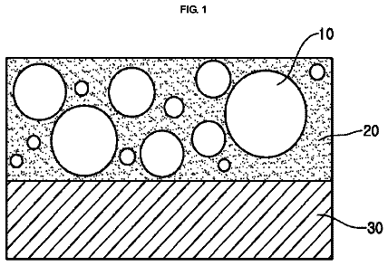
FIG. 1 shows an illustration of the particle size optimization and encapsulation of the mixed metal borohydrides.
FIGS. 2A-2B show the gravimetric hydrogen density of the homometallic borohydride compounds.
FIGS. 3A-3B describe the precursor compounds and the mixed metal borohydride compounds in FIGS. 2A-2B by the generic formulas.
FIG. 4 shows by combining a compound from Group A with one from Group B in the appropriate stoichiometry and removal of solvent, a wide variety of mixed metal borohydride complexes or reactive borohydride complexes can be synthesized.
FIG. 5 illustrates examples of mixed metal borohydrides that can be created.
FIG. 6 illustrates compounds produced based mixed metal borohydrides.
All descriptions and callouts in the Figures and all content therein are hereby incorporated by this reference as if fully set forth herein.
Detailed description of the preferred embodiments
The embodiments of the present inventions described below are not intended to be exhaustive or to limit the invention to the precise forms disclosed in the following detailed description. Rather the embodiments are chosen and described so that others skilled in the art may appreciate and understand the principles and practices of the present inventions.
All publications and patents mentioned herein are incorporated herein by reference in their respective entireties for the purpose of describing and disclosing, for example, the constructs and methodologies that are described in the publications which might be used in connection with the presently described invention. The publications discussed above and throughout the text are provided solely for their disclosure prior to the filing date of the present application. Nothing herein is to be construed as an admission that the inventor is not entitled to antedate such disclosure by virtue of prior invention.
It is to be understood that the invention may assume various alternative orientations and step sequences, except where expressly specified to the contrary. It is also to be understood that the specific processes described in the following specification are simply exemplary embodiments of the inventive concepts defined in the appended claims. Hence, specific measurements and other physical characteristics relating to the embodiments disclosed herein are not to be considered as limiting, unless the claims expressly state otherwise.
Unless otherwise specified, the following definitions and methods are used herein: “mixed metal borohydrides” means a borohydride compound that contains two or more different metals; “homometallic borohydride” means a borohydride compound containing one metal; “nanoparticle,” as generally used herein refers to particle or a structure in the nanometer (nm) range, typically from about 0.1 nm to about 1000 nm in diameter; “wt %” means weight percent; “THF” means tetrahydrofuran; “TGA” means thermogravimetric analysis; and “GC/MS” means gas chromatography/mass spectrometry.
Unless otherwise specified herein, all disclosed characteristics, values and ranges are as determined at room temperature (20° C. to 25° C.).
The alkali metal borohydride compounds LiBH4, NaBH4, and KBH4 are commercially available. The borohydrides of the alkaline earth and light transition metals, Mg(BH.sub.4).sub.2, Al(BH.sub.4).sub.3, Mn(BH.sub.4).sub.2, Zn(BH.sub.4).sub.2, Zr(BH.sub.4).sub.4, Ti(BH.sub.4).sub.3, and Sc(BH.sub.4).sub.3 are for the most part known compounds and their solution synthesis has been described. Briefly, these compounds are prepared as follows according to literature reports. Magnesium Borohydride (Zanella, P.; Crociani, L.; Masiocchi, N.; Biunchi, G. Inorg. Chem. 2007, 46, 9039-9041.); Two methods have been demonstrated for the preparation of magnesium borohydride (Mg(BH.sub.4).sub.2), reaction of commercially available Mg(nBu).sub.2 with borane-methyl sulfide in toluene, and isolation of the precipitate, and reaction of a toluene solution of Al(BH.sub.4).sub.3 (described below) with Mg(nBu).sub.2, and isolation and purification of the precipitate. Both methods furnish the desired product in high yield. Aluminum Borohydride (Zanella, P.; Crociani, L.; Masiocchi, N.; Biunchi, G. Inorg. Chem. 2007, 46, 9039-9041.): A toluene solution of aluminum borohydride (Al(BH.sub.4).sub.3) was prepared in 78% yield by reaction of purified AlC13 with lithium borohydride, followed by distillation of the filtrate. Manganese Borohydride (Makhaev, V. D.; Borisov, A. P.; Gnilomedova, T. P.; Lobkovskii, e. B.; Chekhlov, A. N. Russ. Chem. Bull. 1987, 36(8), 1582-1586.): The THF adduct of manganese borohydride (Mn(BH.sub.4).sub.2.3THF) was obtained by reaction of MnC1.sub.2 with an excess of sodium borohydride followed by filtration and purification to remove excess sodium borohydride. Titanium Borohydride (Mirviss, S. B.; Dougherty, H. W.; Looney, R. W. U.S. Pat. No. 3,310,547 Mar. 21, 1967.): A THF solution of titanium borohydride (Ti(BH.sub.4).sub.3) was prepared by reaction of titanium tetraisopropoxide with diborane in THF. The titanium was reduced from the +4 to +3 valence state during the reaction. When complexed with two and three molecules of THF the titanium compounds are blue and reddish-violet crystalline solids, respectively. Scandium Borohydride (Marks, T. J.; Kolb, J. R. Chem. Rev. 1977, 77, 263-293. Morris, J. H.; smith, W. E. J. Chem. Soc., Chem. Commun. 1970, 245.): Treatment of anhydrous scandium (III) chloride with a slight excess of lithium borohydride in THF furnished a volatile white solid of Sc(BH.sub.4).sub.3.THF. Zinc Borohydride (Pelter, A.; Smith, K.; Brown, H. C. “Borane Reagents” 1988, Academic Press, ISBN 0-12-549875-6, p 414.): A THF solution of zinc tetrahydroborate (Zn(BH.sub.4).sub.2) was prepared by reaction of two equivalents of sodium borohydride with ZnC1.sub.2 in THF in quantitative yield. The supernatant liquid was free of chloride according to a silver nitrate test. The solution could be stored under N.sub.2 and used as required. Zirconium Borohydride (Marks, T. J.; Shimp, L. A. J. Am. Chem. Soc. 1972, 94, 1542-1550. Williams, D. R.; Benbow, J. W.; Sattleberg, T. R.; Ihle, D. C. Tetrahedron Lett. 2001, 42, 8597-8601.): This compound was prepared neat or as an ethereal solution by reaction of zirconium (IV) chloride with either lithium or sodium borohydride.
As described above, once the mixed metal borohydrides are created, the particle size can be optimized and coating protocols can be used to create a stabilizing shell of inert material, as illustrated in the FIG. 1
1. FIGS. 2A-2B shows the gravimetric hydrogen density of the homometallic borohydride compounds on the left and some mixed metal borohydride compounds on the right. By combining a compound from one group with another in the appropriate stoichiometry at an appropriate temperature, a wide variety of mixed metal borohydride complexes can be synthesized.
The equations shown below are examples of the reactions to create mixed metal borohydrides. LiBH.sub.4+Mg(BH.sub.4).sub.2.fwdarw.LiMg(BH.sub.4).sub.3 4LiBH.sub.4+3Mg(BH.sub.4).sub.2.fwdarw.Li.sub.4Mg.sub.3(BH.sub.4).sub.10 Mg(BH.sub.4).sub.2+Ti(BH.sub.4).sub.3.fwdarw.MgTi(BH.sub.4).sub.5
The precursor compounds and the mixed metal borohydride compounds in FIGS. 2A-2B can be described by the generic formulas, such as shown in FIGS. 3A and 3B . The binary (i.e., two metals) complex hydride compositions are derived by the combination of parent compounds from the different groups. However, it should be noted that, as shown in the examples, the mixed metal borohydride compounds can have more than two metals.
For example, FIG. 3A shows groups of homometallic borohydride precursor compounds. Groups A and B can be prepared using solution methods or purchased if commercially available. By combining a compound from Group A with one from Group B in the appropriate stoichiometry and removal of solvent, a wide variety of mixed metal borohydride ate complexes or reactive borohydride complexes can be synthesized, as seen in the list in the block on the right of FIG. 4 , where the Na and K cations in parentheses are alternatives to Li. Although illustrated using a 1:1 mole ratio of a compound from Group A with Group B, other mole ratios can be used. The materials can be converted to nanoparticles, or directly prepared as a monodispersion of nanoparticles in the target size range of 5-50 nm. It is believed that particle size can effect the dehydrogenation temperature.
Once nanoparticles of the optimal size are prepared, coating protocols can be used to create a stabilizing shell of inert material. The goal of the stabilization is both chemical, to reduce the flammability of the materials and prevent degradation, and mechanical, to reinforce the material so that any structural changes during dehydrogenation (and potentially, rehydrogenation cycles) are accommodated without loss of reactivity. By keeping the shell layer very thin compared to the size of the core, the impact on gravimetric and volumetric hydrogen density is minimized.
Examples of mixed metal borohydrides that can be created are summarized in FIG. 5 . As noted above, having a hydrogen storage compound that can release hydrogen with a 100° to 400° C. range is preferred. Even more preferential is a range of 100° to 250° C. The following compounds are ones that should release hydrogen within the preferred range. As the gravimetric capacity increases, a higher desorption temperature is allowable given the benefit of hydrogen storage and release capacity.
Single experiments were performed for the preparation of Li.sub.2Mg(BH.sub.4).sub.4 and Li.sub.3Mg(BH.sub.4).sub.5 and some characterization was carried out. The Mg(BH.sub.4).sub.2 was prepared using literature methods and blended with a commercial solution of LiBH.sub.4 in ether at low temperature. Upon thermolysis Li.sub.2Mg(BH.sub.4).sub.2 began to evolve H.sub.2 at 130° C. and delivered 10.5 wt % H.sub.2 after heating to 375° C. The Li.sub.3Mg(BH.sub.4).sub.5 sample began to lose H.sub.2 at 166° C. and delivered 7.8 wt % H.sub.2 after heating to about 370° C. The additional weight loss in the TGA is probably residual solvent, as the GC/MS analysis of the headspace only showed trace amounts of solvents and did not show the presence of diborane/pentaborane. Similarly, an attempt was made to prepare Li.sub.3Ti(BH.sub.4).sub.6 by blending a commercial solution of LiBH.sub.4 in ether with Ti(BH.sub.4).sub.3.THF prepared using literature methods (Franz, K.; Fusstetter, H.; Nöth, H. Z. anorg. Allg. Chemie 1976, 427(2), 97-113.). Upon thermolysis the tarry aubergine colored material began to release H.sub.2 at 159° C. and delivered 7.3 wt % H.sub.2 after heating to 292° C.
For example, thin polyelectrolyte or polymer-inorganic hybrid coatings can be added using layer-by-layer self-assembly techniques, such as described by Dobbins et al. ( Material Matters 2007, 2
19) and others (Broderick et al., Chem. Mater. 2012, 24(10), 1786; Borodina et al., ACS Applied Mater. Interfaces 2009, 1
996) for encapsulation of metal hydrides. Alternatively, uncharged polymers can be deposited on metal borohydrides using an interfacial polymer precipitation protocol that is induced by solvent evaporation (Borodina et al., J. Materials Chemistry 2010, 20(8), 1452). Thus, the mixed metal borohydrides can be formed into nanoparticles that can be encapsulated. The goal of the stabilization is both chemical, to reduce potential flammability of the materials and prevent degradation, and mechanical, to reinforce the material so that any structural changes during dehydrogenation are accommodated and volume expansion is minimized. By keeping the shell layer very thin compared to the size of the core, the impact on gravimetric and volumetric hydrogen density is minimized. EXAMPLES Example 1 Preparation of Li3Mg(BH4)5
Mg(BH.sub.4).sub.2 was prepared from dibutylmagnesium and borane-methyl sulfide complex as described in the literature (Zanella, P.; et al. Inorg. Chem. 2007, 46, 9039-9041). A 0.5 M solution of Mg(BH.sub.4).sub.2 was prepared by dissolving 0.498 g of Mg(BH.sub.4).sub.2 (9.22 mmol) in 10 mL of anhydrous diethyl ether with stirring under Ar at room temperature. A commercial 0.5 M LiBH4 in diethyl ether (55.32 mL, 27.66 mmol) was added to the Mg(B1-14)2 solution using a canula. The resulting mixture was stirred overnight at room temperature. Solvent was removed in vacuo and 1.6 g of white product (Li.sub.3Mg(BH.sub.4).sub.5 complexed with residual solvent) was obtained after drying on a vacuum line overnight at room temperature. Upon thermolysis, the Li.sub.3Mg(BH.sub.4).sub.5 sample began to lose H.sub.2 at 166° C. and delivered 7.8 wt % H.sub.2 (measured) after heating to about 370° C. Example 2 Preparation of Li2NaMg(BH4)5
Mg(BH.sub.4).sub.2 is prepared from dibutylmagnesium and borane-methyl sulfide complex as described in the literature (Zanella, P.; et al. Inorg. Chem. 2007, 46, 9039-9041). A 0.5 M solution of Mg(BH.sub.4).sub.2 is prepared by dissolving 0.27 g (5.00 mmol) of Mg(BH.sub.4).sub.2 in 10 mL of anhydrous diethyl ether with stirring under Ar at room temperature. A commercial 0.5 M LiBH.sub.4 in diethyl ether (20 mL, 10.00 mmol) is combined with a solution of NaBH.sub.4 prepared by dissolving 0.19 g of NaBH.sub.4 in 10 mL of anhydrous 1,2-dimethoxyethane. The Mg(BH.sub.4).sub.2 solution is added to the LiBH.sub.4/NaBH.sub.4 solution using a syringe. The resulting mixture is stirred overnight at room temperature. The solvent is removed in vacuo and the resulting product (Li.sub.2NaMg(BH.sub.4).sub.5) is dried on a high vacuum line overnight. This material contains approximately 14.8 wt % H.sub.2 (theoretical). Example 3 Preparation of Li4A13(BH4)13
Al(BH.sub.4).sub.3 (1.42 g, 19.889 mmol) is prepared as described by Zhao, J-C, et al. ( J. Phys. Chem. C. 2009, 113, 2) and dissolved in anhydrous diethyl ether as described by Bird and Wallbridge (J. Chem. Soc. 1965, 3923). A commercial 0.5 M LiBH.sub.4 in diethyl ether (53 mL, 26.52 mmol) is added to the Al(BH.sub.4).sub.3 solution by syringe at −78° C. The resulting mixture is allowed to warm slowly to room temperature and stirred for three hours under Ar. The solvent is removed in vacuo and the resulting product (Li.sub.4A1.sub.3(BH.sub.4).sub.13) is dried on a high vacuum line overnight. This material contains approximately 17.2 wt % H.sub.2 (theoretical). Example 4 Preparation of Li3Ti(BH4)6
The description continues in the full USPTO document.
 Lapsed, fee not paid2 drawings