 Lapsed, fee not paid6 drawings
Software & Apps · US 9,946,538 B2
Method and apparatus for providing hardware support for self-modifying code
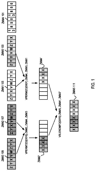
A method and apparatus for providing support for self modifying guest code.
US 9,946,551 B2 · Assignee: AXION RESEARCH INC. · Inventors: Sato; Tomoyoshi et al.
Sheet 1 of 29 from the published document. All sheets in the USPTO PDF
A netlist converter, which generates configuration information for reconfiguring a reconfigurable logic operation unit, includes: a mapping unit that enumerates k-feasible cuts where the number of nodes after cutting is an integer k or fewer, out of all cuts for each node included in a netlist generated based on a specification to be processed in the logic operation unit; and a generating unit that generates configuration information including element reconfiguration information that reconfigures elements by selecting cuts assigned to the elements out of the enumerated k-feasible cuts and channel reconfiguration information for reconfiguring the data transfer channels to realize the netlist by connecting the reconfigured elements.
PCT Publication WO2005/022380 discloses a data processing system that uses architecture code including: object circuit information for dynamically mapping an object circuit, which forms at least part of a circuit for executing an application, onto part of a reconfigurable logic circuit; interface circuit information for mapping an interface circuit, which connects to the object circuit, onto the logic circuit; and environmental conditions to be realized in the interface circuit.
1 of 29 drawing sheets so far from the published document, cropped to the drawing. Every sheet is in the USPTO PDF.
What the patent claimed, word for word. All of it is now free to use.
The present invention relates to a system and method that generate information that reconfigures a reconfigurable logic operation unit.
PCT Publication WO2005/022380 discloses a data processing system that uses architecture code including: object circuit information for dynamically mapping an object circuit, which forms at least part of a circuit for executing an application, onto part of a reconfigurable logic circuit; interface circuit information for mapping an interface circuit, which connects to the object circuit, onto the logic circuit; and environmental conditions to be realized in the interface circuit.
There is demand for a system and method that generate configuration information to be implemented in an system in which circuits can be reconfigured.
One aspect of the present invention is a system that generates configuration information that reconfigures a reconfigurable logic operation unit. The logic operation unit (logical operation unit) includes: elements that are reconfigurable elements and each include an integer k number of inputs; and reconfigurable data transfer channels that are channels for transferring data used in operations between a plurality of the elements. The system includes: a unit that enumerates k-feasible cuts, where the number of nodes after cutting is no greater than the integer k, out of all cuts of respective nodes included in a netlist generated based on a specification to be processed in the logic operation unit; and a generation unit that generates the configuration information that includes element reconfiguration information that reconfigures the elements by selecting cuts assigned to the elements out of the enumerated k-feasible cuts and channel reconfiguration information that reconfigures the data transfer channels so as to realize the netlist by connecting the reconfigured elements.
It is desirable for the generation unit to include a unit that generates the configuration information that includes the element reconfiguration information and the channel reconfiguration information divided into units for reconfiguring the logic operation unit in a time division. It is also desirable for the unit that enumerates to include a unit that detects duplication in the enumerated k-feasibility cuts.
Another aspect of the present invention is a method of generating configuration information for reconfiguring a reconfigurable logic operation unit using a computer including a CPU and a memory. The method includes the following steps. 1. Enumerating k-feasible cuts, where the number of nodes after cutting is no greater than the integer k, out of all cuts of respective nodes included in a netlist generated based on a specification to be processed in the logic operation unit and 2. Generating the configuration information that includes element reconfiguration information that reconfigures the elements by selecting cuts assigned to the elements out of the enumerated k-feasible cuts and channel reconfiguration information that reconfigures the data transfer channels so as to realize the netlist by connecting the reconfigured elements.
It is desirable for the step of generating to include a unit that generates the configuration information that includes the element reconfiguration information and the channel reconfiguration information divided into units for reconfiguring the logic operation unit according to time division. It is also desirable for the method to include detecting duplication in the enumerated k-feasibility cuts. This method can be provided as a program (program product) that generates configuration information for reconfiguring a reconfigurable logic operation unit using a computer including a CPU and a memory. The program includes instructions that execute the steps described above.
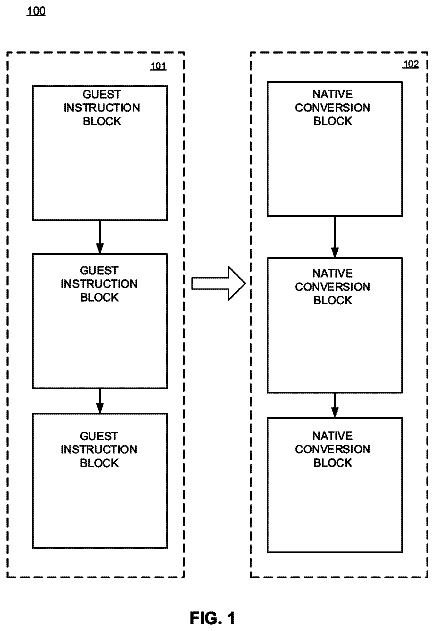
FIG. 1 is a block diagram of a data processing system.
FIG. 2 shows progressive enlargements of the overall configuration of a DRP subsystem (ANR).
FIG. 3 shows how a circuit is reconfigured on a cycle by cycle basis.
FIG. 4 shows the flow of data in an ANR.
FIG. 5 shows a different flow of data.
FIG. 6 shows how the wiring channels of an ANR are used according to time division.
FIG. 7 is a diagram of an ANR-BASE module.
FIG. 8 is a diagram of an ANR-C1×4 module.
FIG. 9 is a diagram of an ANR-C1 module.
FIG. 10 is a diagram of a wiring channel cell.
FIG. 11 is a diagram of a wiring channel cell.
FIG. 12 is a diagram of a wiring channel cell as wired logic.
FIG. 13 is a diagram of a different wiring channel cell.
FIG. 14 is a diagram of a network of wiring channel cells.
FIG. 15 is an example where logic is implemented by slicing in a time division.
FIG. 16 is an example where an application is implemented with a data processing system as a platform.
FIG. 17 is an example of a design flow.
FIG. 18 is a block diagram showing the overall configuration of a netlist converter.
FIG. 19 is an example where a logic circuit is implemented using an LUT.
FIG. 20 is an example where a netlist is implemented in an ANR.
FIG. 21 is an example where a different netlist is implemented.
FIG. 22 is a flowchart showing an overall process that generates configuration information in a netlist converter.
FIG. 23 is an example of optimization by a Boolean network.
FIG. 24 is a diagram showing how processing separated into cuts (combinations of nodes) is implemented by LUTs.
FIG. 25 is a diagram showing a method of searching for cuts.
FIG. 26 is a diagram showing an example of RTL.
FIG. 27 is a diagram showing an example of a netlist.
FIG. 28 is a diagram showing an example of a data flow graph.
FIG. 29 is a diagram showing an example of mapping information of nodes.
FIG. 30 is a diagram showing a packing algorithm.
FIG. 31 is a diagram showing an example of mapping information that has been optimized.
FIG. 1 shows an overview of a data processing system (processing apparatus, processing device) 1 including a reconfigurable circuit (or “DRP subsystem”) 10 . The system 1 is a type that boots the OS from flash memory and includes DDR3-DRAM 2 a as main memory. The system 1 can be mass produced as a POP (Package On Package) for example, or by another method. The system 1 includes a bus (AXI bus) 2 c that uses an internal bus architecture such as AMBA 3.0, a CPU (CPU core) 2 b, and the DRP subsystem 10 that is connected to the CPU 2 b by the bus 2 c. The DRP subsystem 10 includes a configuration memory 10 m that stores information (“configuration information”) used for reconfiguring.
In the system 1 , a system (AxioNipeR) that has been newly developed by the applicant is used as the DRP subsystem 10 . The DRP subsystem 10 includes a plurality of logic elements (or simply “elements”) that have an appropriate number of inputs and outputs and perform logic operations (logical operations) that can be changed (reconfigured) on a cycle-by-cycle basis (in cycle units), and the DRP 10 may be any device that can be partly reconfigured on a cycle by cycle basis. The DRP subsystem (AxioNipeR) 10 in the present embodiment is equipped with a matrix (array) in which 64 elements are laid out in both the vertical and horizontal directions.
The system 1 further includes a USB controller 2 r, a high-definition multimedia interface controller 2 d, a security engine controller 2 e, a LAN controller 2 f, a DMA controller 2 g, a PCI controller 2 h, an SDXC controller 2 i, a SATA controller 2 j, an MIPI interface controller 2 k, an LCDC controller 2 l, a NAND flash controller 2 m, a peripheral function 2 n, a peripheral function register 2 o, and an INTC controller 2 s, with such components being connected via the internal bus 2 c and bridges 2 p, 2 q.
The DRP subsystem (AxioNipeR, hereinafter simply “ANR”) 10 is a Dynamic Reconfigurable Processor, and includes an array with a fine grain configuration. By equipping the system 1 with the ANR 10 , it is possible, in fields such as chemical substance analysis where there is demand for parallel data processing on a comparatively large scale, to carry out parallel data processing that is grouped into each stage of an analysis process and to also use resources for other processing in parallel or according to time division (in a time division). As one example, a method where a hardware area for the maximum execution performance is provided as the ANR 10 and other processing is carried out in a given order as parallel processing with such area as a maximum is extremely economical. It is especially effective to successively determine and execute such parallel data processing.
An effect is also achieved whereby the hardware implementation itself can be changed by software patches and upgrades in response to future requests for improvement in system demands and/or demands for increased performance. In reality, there is great need for LSIs that are capable with future changes, which greatly reduce the risk involved with system implementation and effectively shorten the time required for hardware development. A platform strategy where different processing and/or applications are executed by the same computational device has the important advantages of shortening development and flexibly coping with customer demands.
Although a typical FPGA is known as a reconfigurable device that has a fine grain configuration, the ANR 10 overcomes the problem that an FPGA has poor efficiency and a low operation frequency and also solves the problem that reconfigurable devices with a fine grain configuration have low flexibility.
FIG. 2 shows an overview of the ANR 10 . FIG. 2 shows an enlargement of a region (tile) 19 , which is part of the ANR 10 taken from the system 1 and includes a plurality of cells 11 , and also shows an enlargement of the overall configuration of a cell 11 . One cell 11 has a plurality (a maximum of 8 or 16) of units of reconfiguration information (configuration information) and generates a circuit by dynamically switching between such information in one clock. The respective cells 11 are capable of operating as other logic operation units (logic operation circuits) one clock later, for example, after 1 ns, and for that reason a single cell 11 appears to function as a plurality of multiplexed circuit modules.
The ANR 10 has a symmetric network topology, with it being possible to transfer data in the up-down and left-right directions using connection channels between adjacent cells and global connection channels 20 between distant cells. Although an example where the cells 11 are laid out in two dimensions is described below, the cells 11 may be laid out in three dimensions, and the connection channels 20 may also have a three-dimensional structure. In addition, the connection channels 20 may be something that is fixed to a circuit board or the like in the manner of wiring or may be a space in which signals propagate, such as with optical communication (for example, visible light communication), and additionally, the connection channels 20 may be something that does not have fixed paths and connects the cells 11 while being capable of dynamic reconfiguration.
The global connection channels 20 include a system that transfers signals (data) that have been multiplexed in a time division (time-division multiplexing), which increases the utilization rate of the channels 20 and avoids incurring a wiring cost. In the same way as circuit generation, scheduling of the channel connections is carried out via prescheduling according to dataflow analysis, which will be described in detail later. The data transfer method may be a packet data transfer method using attached labels or may be a data transfer method with a simple structure achieved by indicating the data creation and reception timing. It is desirable for the global connection channels 20 to provide enough bandwidth for data transfer by circuits that have been generated by dynamic events, which makes it possible to generate circuits in the ANR 10 according to dynamic events.
The respective cells (that corresponds each element, respective logic operation elements) 11 in the ANR 10 are multiplexed in a time division and have a configuration that can be configured on a single clock (1 ns) by single clock basis (in single clock (1 ns) units). By designating the necessary configuration, it is possible to achieve an arbitrary circuit configuration by referring to the configuration memory 10 m that has been set in advance.
FIG. 3 shows an example where a circuit is reconfigured by an actual change in configuration. Such change in configuration can be carried out in units of the cells 11 (cell by cell basis) or in units that include a plurality of cells 11 . Depending on the function module (configuration module) to be reconfigured, it is possible to treat a plurality of cells as a single module unit (or “tile”) 19 .
In FIG. 3 , the tile 19 functions as an adder circuit 18 a in the first clock cycle (n clock), functions as a decoder circuit 18 b in the second clock cycle (n+1 clock), and functions as a shifter circuit 18 c in the third clock cycle (n+2 clock). As one example, by providing a register that stores an operation result inside or outside the tile 19 , it becomes possible for input/output data 18 x that has been calculated in each clock cycle to propagate (i.e., be inputted and outputted) beyond the functions that are being reconfigured, which makes it possible for a plurality of logic functions to be seamlessly multiplexed onto what is physically the same tile 19 . Accordingly, it is possible to reduce the circuit scale that is needed to carry out a large number of and/or complex logic operations. It is of course also possible for a plurality of logic functions to be implemented in what is physically not the same tile 19 either in a time division or in parallel, and also possible to reconfigure by changing tiles 19 that physically overlap in part and/or changing the size of the tiles 19 used for the implementation.
As shown in FIGS. 4, 5, and 6 , the flow of the data 31 is also multiplexed in the ANR 10 . The direction of the data inputted into and outputted from a given cell 11 can be controlled by an inter-connection channel 28 that connects between cells 11 and connects the cell 11 to the global connection channels 20 . One example of the inter-connection channel 28 is a crossbar switch and by using an internal crossbar switch, it is possible to control output and input to two components (cells 11 , global connection channels 20 ) simultaneously. The global connection channels 20 include wiring channels 29 that carry out data transfers that pass over the cells 11 . The wiring channels 29 include two channels in the vertical direction and two channels in the horizontal direction. By using time slots that are decided between respective cells 11 in the same way as the configuration information of the cells 11 , the global connection channels 20 are capable of carrying out data transfers between a plurality of cells 11 by time multiplexing on one channel.
The tile 19 shown in FIG. 4 is configured so that the data 31 flows in the downward direction and rightward direction between the cells 11 . The tile 19 shown in FIG. 5 is configured so that the data 31 flows in the leftward direction and upward direction between the cells 11 .
FIG. 6 shows, by way of a timing chart, how multiplexing is carried out on a wiring channel X 6 in the horizontal direction and a wiring channel Y 2 in the vertical direction. FIG. 6( a ) shows how a process (a logic operation) where data is exchanged between the cell C 33 and the cell C 11 and a process where data is exchanged between the cell C 32 and the cell C 21 are configured in physically the same tile 19 in a time division. FIG. 6( b ) is a timing chart showing how the wiring channels X 6 and Y 2 are occupied, and shows that the same wiring channels X 6 and Y 2 are occupied in a time division using slots TS 1 in which a process (a logic operation) where data is exchanged between the cell C 33 and the cell C 11 is configured and slots TS 3 in which a process where data is exchanged between the cell C 32 and the cell C 21 is configured.
The ANR 10 that is a logic operation unit that includes cells (elements, function cells) 11 , where logic operations (function operations) are defined, and wiring channel cells 20 , which carry out data transfer control between the cells 11 . Logic operations to be implemented in a tile 19 that includes the plurality of the cells 11 and/or in the ANR 10 that is a matrix of cells 11 , is usually recognized as a circuitry. However, with the ANR 10 , since it is possible to change the configuration on a clock-by-clock basis, it is not necessary to make a meaningful circuitry, or a circuitry whose logic operations can be clearly understood or comprehended, and it is sufficient to configure the tile 19 or the ANR 10 so that a predetermined logic operation result is obtained after a predetermined number of clock cycles have elapsed (i.e., with a predetermined latency). The respective cells 11 are symmetrical and it is possible to configure the ANR 10 by connecting a plurality of cells 11 in the form of tiles (a matrix) in units of N cells by M cells.
The circuit operation of the individual cells 11 is dynamically defined by the configuration information (reconfiguration information, function configuration information). The individual cells 11 may be independently reconfigured or a plurality of cells 11 may be simultaneously reconfigured. The logic operations (i.e., circuit configuration) of the cells 11 are reconfigured in a minimum time of one clock cycle (one cycle) to make it possible to use the reconfigured logic operation. Although it is also possible for the cells 11 to be set so that the same logic operation is carried out across a plurality of clock cycles, such situation can be understood as the cells 11 being reconfigured so that the same logic operation is carried out in single clock cycles.
FIGS. 7, 8 and 9 show the hierarchical configuration of the cells 11 used in the ANR 10 . FIG. 7( a ) shows the configuration of a cell (element) 11 . Such cell 11 is also referred to an ANR-BASE module 14 . The ANR-BASE module 14 is a top module of a function cell of the ANR 10 and includes four ANR-C1×4 modules 13 , three types of fixed auxiliary logic modules 14 b, selectors 14 c that select the outputs of the auxiliary logic modules 14 b, and an auxiliary operation configuration selection unit 14 a that controls (decides) the content of an auxiliary operation by controlling the selectors 14 c. Although the fixed auxiliary logics supported by the auxiliary logic modules 14 b is not specified or not limited, such logics may include carry look ahead for addition (summation) operations and auxiliary logic aimed at a decoder.
FIG. 7( b ) shows a terminal chart of the ANR-BASE module 14 . The ANR-BASE module 14 is a module (element) that is capable of carrying out logic operations with four 4-bit inputs and four 4-bit outputs. The logic operation to be reconfigured is designated by a configuration reservation address CRA. Configuration information (configuration setting information) CWD for reconfiguring is transferred to each ANR-BASE module 14 with appropriate timing, is written in advance into an address in a configuration memory that has been reserved by a configuration setting address CWA, and is read out using the configuration designating address CRA.
FIG. 8( a ) shows the configuration of an ANR-C×4 module 13 . Such ANR-C×4 module 13 is constructed from the four ANR-C1 modules 12 and carries out a logic operation with a single 4-bit input (four 1-bit inputs) and a single 4-bit output. FIG. 8( b ) is a terminal chart of the ANR-C×4 module 13 .
FIG. 9( a ) shows the configuration of an ANR-C1 module 12 . The ANR-C1 module 12 is a logic element with four 1-bit inputs and one 1-bit output that carries out a logic operation defined by 3-bit function configuration information CWA. The ANR-C1 module 12 includes a configuration memory (configuration RAM) 12 a with a capacity of 17 bits by 16 words, a read-side address decoder 12 b into which the configuration designation address CRA is inputted, a write-side address decoder 12 d into which the configuration setting address CWA is inputted, a data input interface 12 c into which the configuration setting information CWD is inputted, an output-side selector 12 e from which the a result where the input data A has been logically operated by logic selected by the configuration designation address CRA is outputted, and a selector 12 f that selects the output X from the direct operation result of the combinational circuit and the output as a sequential circuit with timing set by the FF 12 g.
The timing chart in FIG. 9( b ) shows the timing at which the configuration designation address CRA is supplied, the timing at which the input A is supplied, and the timing at which the result X of the selected logic operation is outputted. FIG. 9( c ) also shows a terminal chart of an ANR-C1 module 12 .
In the ANR-C1 module 12 , by setting a value composed of 16 types of “0/1” pattern for four inputs (i.e., a 4-bit input) as the configuration information, it is possible to realize (implement) a combinational circuit that carries out an arbitrary logic operation. The ANR-C1 module 12 has a four-input, one-output circuit structure defined by the function configuration information CRA as a basic cell and is capable of selecting whether to output as a combinational circuit or to output as a sequential circuit with timing using the FF 12 g. A maximum of 16 types of configuration information CWD can be stored in the RAM (or FF) 12 a and the stored configuration information CWD can be switched in single clock cycles according to the configuration designation address CRA. Accordingly, the ANR-C1 module 12 is a logic operation element that can be dynamically reconfigured in one clock cycle.
The ANR-C×4 module 13 shown in FIG. 8( a ) is set as a single element in which four ANR-C modules 12 that have the same input signals (four signals) A are combined. The ANR-BASE module 14 shown in FIG. 7( a ) is constructed of four of the ANR-C×4 modules 13 shown in FIG. 8( a ) as a single function cell. Switching control for the configuration information CWD may be carried out by supplying the configuration designation address CRA from an external controller, such as the CPU 2 b, based on an external event or the like, or may be carried out autonomously by having the configuration designation address CRA generated inside the ANR 10 . Switching control for the configuration information CWD may be carried out by generating the configuration reservation addresses CRA in a predetermined order or cyclically according to events inside an ANR-BASE module 14 , an ANR-C×4 module 13 , and/or an ANR-C1 module 12 .
The function configuration information CWD is loaded from an external memory using a dedicated bus before a predetermined application, function, or logic is executed. Dedicated wiring that delivers the configuration information CWD may be provided, or shared use may be made of the data transfer wiring channel 20 . By repeatedly using the configuration information CWD inside the memory 12 a, it is possible to reduce the hardware and the temporal cost required to rewrite the configuration information CWD. By using a two-port RAM or the like, the rewriting of the configuration information CWD can be changed both during execution and during idling by a function cell 11 .
The connection configuration of the wiring channel cell (ANR-CORE) 21 is shown in FIG. 10 . The ANR-CORE 21 includes a function cell 11 (ANR-BASE module 14 ) and a wiring channel 27 for transferring the output data of the cell 11 to an adjacent function cell 11 or to a function cell 11 that is separated by one or more cells. The ANR-CORE 21 also includes a connection circuit for connecting to the global connection channels 20 . The selection of the transfer source according to the wiring channel 27 and the global connection channels 20 and the designation of the transfer timing is dynamically changed according to the wiring configuration information, so that it is possible to change the selection of transfer source in a minimum of one clock cycle.
The wiring channel cell (interconnection channel cell, connection channel cell, ANR-CORE) 21 has a function cell 11 (ANR-BASE 14 ) included thereinside and the ANR 10 is constructed by connecting the wiring channel cells 21 as each wiring channel cell being a tile. The basic functions of the ANR-CORE 21 are as follows. Output data (each of which is sixteen-bit) from the four function cells 11 adjacent in the up, down, left, and right directions are fetched, selected according to the wiring configuration information, and set as the input of the present function cell (own function cell) 11 . The global wiring channels 20 are provided for data transfers that pass over cells 11 . The global wiring channels 20 that are managed (connected) for respective ANR-CORE 21 (in units of the ANR-CORE 21 ) are composed of two channels 20 d and 20 u in the down and up directions and two channels 20 l and 20 r in the left and right directions, and data transfers on the respective channels 20 may have directionality (from top to bottom, from bottom to top, from right to left, and from left to right). Tag information or the like is not included in the data on the global wiring channels 20 , and data transfers are carried out by combining the transmission timing of the ANR-CORE 21 that is the transmission source and the reception timing of the ANR-CORE 21 that is the transmission destination. In one time slot (in a single time slot), only one function cell 11 is capable of outputting data to a wiring channel to be occupied out of the global wiring channels 20 . Such scheduling is carried out in cooperation with the configuration information. The global wiring channels 20 are capable of being driven from a plurality of cells 11 , with scheduling being used to avoid conflicts. The physical means used for multiple driving is decided according to the processing technology, cell specification, or the like that is used in reality. As one example, a wired OR configuration can be used. The wiring channel cell (ANR-CORE) 21 has a bridge mechanism that connects global wiring channels 20 inside the wiring channel cell (ANR-CORE) 21 . By doing so, data from the left or right wiring channels 20 l or 20 r can be transferred to the up or down wiring channels 20 d or 20 u, with transfers in the opposite direction also being possible.
Four signals from the adjacent function cells 11 and four signals from the global wiring channels 20 are inputted into a wiring channel cell 21 , with each input having a 16-bit bus format. Accordingly, a total of 128 input signals are connected to the ANR-CORE 21 . To have such input signals selected with complete freedom, sixteen 128:1 selectors (which are individually selected) would be necessary. For this reason, the circuit scale is suppressed by applying the two restrictions given below. The output of an element unit (ANR-C×4) unit 13 (output on an element by element) is used as a fixed input for another element. As examples, the output of bit 0 of each element 13 is only connected to bit 0 of element inputs and bit 1 is only connected to bit 1 . By doing so, the connection relationship becomes 32:1. However, although the bit position relationship is fixed between elements, by shifting the configuration to a bit at the position to be connected, this is effectively not a logical restriction. The adjacent wiring channels 27 and the global wiring channels 20 from the same direction are switched on an element-by-element basis.
The ANR-BASE module 14 has an interface for four input-outputs for the adjacent modules 14 and four input-outputs for the global wiring channels. In the ANR-CORE 21 , based on wiring configuration information that is internally held, necessary data on the transfer source is referred to at the necessary timing.
FIG. 11 shows the connection configuration of a wiring channel cell (ANR-CORE) 21 . The ANR-CORE 21 includes the ANR-BASE module 14 and the interface 21 a. The interface 21 a includes an interface with four input-outputs for the modules 14 adjacent to the present ANR-BASE module 14 via the wiring channels 27 and an interface with four input-outputs for the global wiring channels 20 . Necessary data on the transfer source is referred to at necessary timing based on the wiring configuration information held inside the ANR-CORE 21 . Sixteen inputs into the ANR-BASE 14 can be selected out of the signals from the adjacent modules 14 and the signals from the connection channels 20 as a rule in one bit units (bit-by-bit basis).
FIG. 12 shows the configuration of the connections between the ANR-BASE module 14 and the global wiring channels 20 in a wiring channel cell 21 . The global wiring channels 20 input into the wiring channel cell 21 from four directions and output in the same directions. Since data is outputted from a plurality of wiring channel cells 21 , a connection interface 21 a for the global wiring channels 20 uses a wired OR configuration in logical terms. The connection interface 21 a includes an output control unit 21 b that selects the output from the ANR-BASE module 14 , and an OR gate 21 c that receives the output selected by the output control unit 21 b and signals transmitted from the global wiring channels 20 .
Signals inputted from the global wiring channels 20 in different directions are inputted into the output control unit 21 b. Accordingly, the connection interface 21 a has a mechanism for driving by outputting, in addition to the output from the present cell (own cell), data from the left and right directions to the global wiring channels 20 in the up and down directions and outputting data from the up and down directions to the global wiring channels 20 in the left and right directions. The connection interface 21 a outputs data of the present cell 21 or data of a global wiring channel 20 in a different direction only in respective specified time slots that were assigned when the configuration was set. The assigning of time slots is also carried out when the configuration is set.
One major advantage of the ANR 10 is the effective usage of the wiring channels. With a conventional FPGA, when a connection between one point and another point is necessary, a wiring channel is reserved regardless of whether or not data transfers are made that becomes cause of increasing in wiring cost. The ANR 10 is capable of multiplexed use of wiring channels in a time division. By reconfiguring the function cells 11 , flexibility is increased and the amounts of logic and wiring are reduced, thereby constructing a system with high cost performance. To realize such system, in addition to the hardware (chip) of the ANR 10 , a high level of software processing is necessary, such as extraction of multiplexed processing according to data flow analysis of an application and precise data transfer scheduling.
The wiring channel cell 21 includes the ANR-BASE module 14 included in the wiring channel cell 21 and a configuration control unit 50 that controls the configuration of the connection interface 21 a and the like. The configuration control unit 50 includes a configuration memory 10 m in which configuration information 230 is stored. As described later, the configuration information 230 includes element reconfiguration information 231 and channel reconfiguration information 232 .
FIG. 13( a ) shows a different example of a wiring channel cell 21 . The connection interface 21 a of the wiring channel cell 21 further includes an AND gate 21 d and as shown by the equivalent gate circuit in FIG. 13( b ) , has a mechanism that drives data by selecting one out of four outputs that are the output from the wiring channel on the preceding stage (that is an additional one), the output from the present cell 21 , an output of data from the left or right direction for a global wiring channel 20 in the up or down direction, and an output of data from the up or down direction for a global wiring channels 20 in the left or right direction.
As shown in FIG. 10 , the ANR 10 includes local wiring channels 27 that are capable of direct data transfers in the four directions up, down, left, and right for the respective cells (ANR-BASE modules) 14 . Accordingly, it is possible to easily cope with a case where a data transfer to an adjacent cell (ANR-BASE module) 14 is carried out. In addition, it is possible to transfer a data operation result back to the cell 14 that outputted the data via a local wiring channel 27 . The cell 14 ( 11 ) to which the data has been sent back carries out an operation that has been reconfigured to another function in the next timing. Since it is possible for data to be sent back, it is possible to use a physically localized layout of the function cells 14 ( 11 ), which facilitates grouping during mapping.
If four signals on the local wiring channels from the adjacent function cells 11 and four signals from the global wiring channels 20 are inputted into a wiring channel cell 21 on 16 bit-buses, the wiring channel cell 21 will be connected to a total of 128 input signals. To have such inputs selected with complete freedom, sixteen 128:1 selectors (which are individually selected) would be necessary. The circuit scale may be suppressed by applying the two conditions given below. The output of an element unit (ANR-C×4) 13 is used as a fixed input for another element. As examples, the output of bit 0 of each element 13 is only connected to bit 0 of element inputs and bit 1 is only connected to bit 1 . By doing so, the connection relationship becomes 32:1. By doing so, although the bit position relationship is fixed between elements, by shifting the configuration to a bit at the position to be connected, this is effectively not a logical restriction. The local wiring channels 27 and the global wiring channels 20 from the same direction are switched in units of the elements 13 . Due to the locality of data, there is a low possibility of the local wiring channels 27 and the global wiring channels 20 from the same direction being mixed.
FIG. 14 shows the network configuration of the ANR 10 . The ANR 10 has the wiring channel cells 21 as a basic configuration that include the function cells 11 . Although the ANR network 10 a has a basic configuration of 64×64, the configuration is not limited to such. The basic operation of the ANR 10 is a combination of data logic operations and data transfers. For this reason, the ANR 10 needs a supply circuit for input data, a storage circuit for output data, and a supply circuit for configuration information. Such functions are realized by the ANR interface module (ANR-IF) 10 b. The ANR-IF 10 b carries out transfers of data and configuration information from the DDR-DRAM 2 a on an AXI bus 2 c, which is the main bus of a digital chip, via the AXI bus interface module (AXI-ANR-IF) 10 c.
The ANR-IF 10 b connects the wiring channels 21 of a peripheral part of the ANR network 10 a and the global wiring channels 20 . The ANR-IF 10 b carries out data transfers to and from the outside via the AXI bus 10 c or dedicated I/O. Although the transferring of the configuration information is carried out by making shared use of the global wiring channels 20 , channels dedicated to such transfer may be provided. The ANR-IF 10 b has a 2 kbyte buffer for inputting/outputting inside the module and carries out inputs and outputs of data to and from the ANR 10 with 16-bit (1 GHz) burst transfers as a maximum.
Configuration information stored in the DDR-DRAM 2 a is supplied to the function cells 21 ( 11 ) and the wiring channels 20 via the global wiring channels 20 . The configuration information may be transferred to each cell 21 before system start-up commences or may be transferred during operation after system start-up has commenced. It is desirable for analysis of the logic circuits and data flows that are necessary for an entire application to be optimized by software, for configuration information to be transferred to the configuration memories of the respective cells 21 whenever possible before system start-up commences, and for the load of data transfers of configuration information after system start-up has commenced to be suppressed.
FIG. 15 shows a model for confirming the basic operation of the ANR 10 . The operation model shows operations as an adder, a subtractor, a decoder, or the like by changing between six configurations of a module with two 4-bit inputs and one 4-bit output. This model maps the adder part onto the basic cells (ANR-C1) 12 . With the present mapping, by dividing into two slices (“slice 1 ” and “slice 2 ”), logic is executed and then what is physically the same cell 13 is reconfigured to other logic.
FIG. 16 shows an example of a system (OLP) 100 that includes the data processing apparatus (system) 1 equipped with the ANR 10 . This system 100 is a system that analyzes data 101 obtained from a sensor such as a FAIMS and is capable of implementing a variety of functions in the ANR 10 in parallel or in time division. The system 100 can be used as a platform for a variety of applications. A number of example applications are healthcare monitoring 100 a, process monitoring 100 b, security monitoring 100 c, and a consumer-oriented odor business application 100 d. Aside from data 101 obtained from a sensor such as a FAIMS (ion mobility sensor) or an MS (mass sensor), auxiliary sensor data 102 such as temperature, humidity, pressure, peripheral images, and GPS and sampling system data 103 , for example, sampling time, and data relating to the sampled material, are inputted into the apparatus 1 .
As examples, a parser 110 that determines the category or the like of a material to be measured and sets analysis conditions, a unit 111 that carries out data correction such as baseline correction, a unit 113 that standardizes peaks to reduce noise, a unit 114 that detects and separates peaks included in the sensor data 101 , an analysis engine 115 that determines types (properties, attributes) and amounts from the separated peaks, an engine 116 that sorts or categorizes chemical substances to be measured from information obtained by the analysis engine 115 using a method such as SOM (Self-Organizing Maps) or a neural network, and a unit (function) 117 that carries out a search of a database inside the apparatus or via a network to determine a chemical substance being measured are mapped onto the ANR 10 according to time division.
The CPU 2 b supports the reconfiguration of the ANR 10 and also realizes a function that supports processing by the ANR 10 . As examples, the CPU 2 b provides a function 124 that accesses a reference database, a function 123 that accesses the cloud (a LAN), a user interface function 122 , and a data acquisition control function 121 . Such functions can be implemented in the ANR 10 using free space and/or free time at the ANR 10 .
There is demand for a large-scale parallel data processing engine for detecting and analyzing chemical substances in real time. By detecting and analyzing chemical substances in real time, it is possible to provide revolutionary services to users such as the identification and quantification of biomarkers used for detecting disease, monitoring of health and/or vital functions, and provision of managed care using remote monitoring technologies. The platform for doing so needs to be intelligent, extensible, and to satisfy a variety of demands relating to applications and performance. In addition to functioning as parallel processing hardware, the apparatus 1 that includes the ANR 10 is hardware that is dynamically programmable, which satisfies the needs described above.
The description continues in the full USPTO document.
About 6,874 words. The USPTO PDF has it with every drawing.
Fees are due 3.5, 7.5 and 11.5 years after grant. This patent expired on April 17, 2026, so the fee marked "not paid" was the one that went unpaid.
SYSTEM AND METHOD THAT GENERATE RECONFIGURATION INFORMATION
Filed Mar 2014 · published Jul 2016System and method that generate reconfiguration information
Filed Mar 2014 · granted Apr 2018Earlier publications, parents and continuations. None of them can still be enforced, or this patent would not be listed.
Prior art cited by the examiner or applicant. Useful when you check your own idea for novelty.
Everything on this page comes from the documents linked above.