Technical field
The present invention relates to an image forming apparatus such as a copying machine, a printer, a facsimile machine, a multi-function machine having a plurality of functions of these machines, and the like.
Background art
In general, in an image forming apparatus of an electrophotographic type, an electrostatic latent image formed on a photosensitive drum as an image bearing member is developed as a toner image with a developer containing a toner and a carrier by a developing device as a developing means. In such a developing device, in a circulating path in a developing container, the toner and the carrier are triboelectrically charged by feeding the developer while stirring the developer by rotating a feeding screw. The developer containing the toner and the carrier gradually lowers in charging performance of the carrier by continuous circulation of the carrier which is not consumed by image formation while being subjected to friction in the developing container. For this reason, ensuring of an average charge performance of the carrier in the developer has been conventionally made by discharging a part of the developer by overflow through a discharge opening provided in the developing container while supplying a new (fresh) developer to the developing container (Japanese Patent Publication Hei 2-21591).
Further, a developing device constituted so that a force, with respect to a circumferential direction or an outward radial direction, acting on the developer by rotation of the feeding screw in an opposing region to a developer discharge opening is made smaller than a force in another region has been proposed (Japanese Laid-Open Patent Application (JP-A) 2000-112238). Specifically, a constitution in which a blade of the feeding screw in the opposing region to the developer discharge opening is made small or a constitution in which the blade is omitted (removed) is employed. SUMMARY OF THE INVENTION Problem to be Solved by the Invention
Here, as in the constitution described in JP-A 2000-112238, when the blade of the feeding screw in the opposing region to the discharge opening is removed or made small in diameter, developer feeding power of the feeding screw in this region lowers. Then, in the neighborhood of the discharge opening, the developer fed by the feeding screw stagnates and a developer surface rises, so that the developer which gets over the discharge opening is discharged so as to level off and overflow the discharge opening.
However, in a constitution in which the developer is thus stagnated, when a charge amount of the developer lowers, flowability of the developer becomes high, and therefore a degree of stagnation of the developer in the neighborhood of the discharge opening becomes small, so that the developer is not readily discharged through the discharge opening. As a result of this, the developer in the developing container increases in amount, so that there is an increasing possibility in some cases that the developer overflows the discharge opening during rising or the like of a developing device and that a rotational load of the feeding screw becomes high and the feeding screw locks.
In view of the above-described circumstances, the direction has been accomplished for properly making discharge of the developer in a constitution in which the developer feeding power of the feeding screw in the opposing region to the discharge opening is low. Means for Solving the Problem
According to an aspect of the present invention, there is provided an image forming apparatus comprising: an image bearing member; a developing device configured to develop a latent image formed on the image bearing member and including a developing container in which a developer is accommodated, a feeding screw configured to feed the developer in the developing container, and a discharge opening provided in a side surface of the developing container so as to oppose the feeding screw and configured to permit discharge of an excessive developer in the developing device; a supplying device configured to supply the developer into the developing container; a driving device configured to rotationally drive the feeding screw; an acquiring portion configured to acquire information on a charge amount of the developer; and a controller configured to control the driving device, wherein the feeding screw is formed so that an outer diameter of a first region including a portion opposing the discharge opening is smaller than an outer diameter of a second region adjacent to the first region, and wherein on the basis of information of the acquiring portion, the controller effects control so that a driving speed at which the feeding screw is driven by the driving device is faster when the charge amount of the developer corresponds to a second charge amount lower than a first charge amount, than when the charge amount of the developer corresponds to the first charge amount.
According to this embodiment, in a state in which the flowability of the developer becomes high and the charge amount is low, control is effected so that a feeding screw driving speed becomes fast (high), and therefore even when the flowability of the developer is high and the developer does not readily stagnate in the neighborhood of the discharge opening, a developer surface is raised and discharge of the developer can be properly performed.
Brief description of the drawings
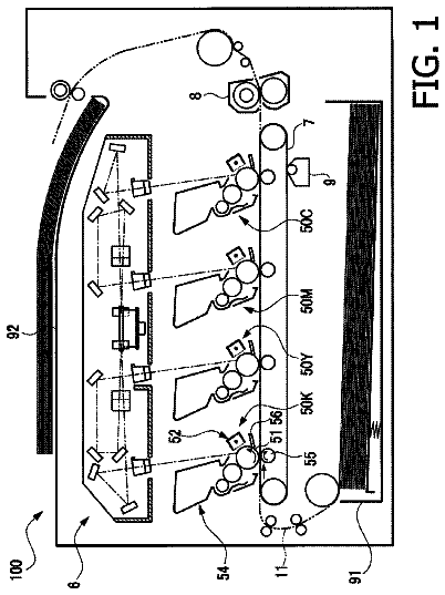
FIG. 1 is a schematic structural view of an image forming apparatus according to a First Embodiment of the present invention.
FIG. 2 is a schematic cross-sectional structural view of a developing device according to the First Embodiment.
FIG. 3 is a schematic longitudinal structural view of the developing device.
FIG. 4 is a schematic view showing a feeding screw in the neighborhood of the developing device according to the First Embodiment.
FIG. 5 includes schematic views showing other 3 examples of the feeding screw in the neighborhood of the developing device according to the First Embodiment.
FIG. 6 is a diagram showing a discharging characteristic of a developer through a discharge opening.
FIG. 7 is a schematic view showing a developer surface in the neighborhood of the discharge opening.
In FIG. 8 , (a) is a schematic view showing the developer surface in the neighborhood of the discharge opening in the case where flowability of the developer is low, and (b) is a schematic view showing the developer surface in the neighborhood of the discharge opening in the case where the flowability of the developer is high.
FIG. 9 is a control block diagram of the image forming apparatus according to the First Embodiment.
FIG. 10 is a flowchart of control during rising of the developing device in the First Embodiment.
FIG. 11 is a diagram showing a change in developer amount in a developing container relative to a developer humidity at each image DUTY in a comparison example to the present invention.
FIG. 12 is a diagram showing a change in developer amount in a developing container relative to a developer humidity at each image DUTY in Embodiment 1 of the present invention.
FIG. 13 is a control block diagram of an image forming apparatus according to a Second Embodiment of the present invention.
FIG. 14 is a flowchart of control during rising of a developing device in the Second Embodiment.
FIG. 15 is a diagram showing a change in developer amount in a developing container relative to a developer humidity at each image DUTY in Embodiment 2 of the present invention.
FIG. 16 is a control block diagram of an image forming apparatus according to a Third Embodiment of the present invention.
FIG. 17 is a flowchart of control during rising of a developing device in the Third Embodiment.
FIG. 18 is a diagram showing a change in developer amount in a developing container relative to a developer humidity at each image DUTY in Embodiment 3 of the present invention.
FIG. 19 is a flowchart of control during rising of a developing device in a Fourth Embodiment of the present invention.
FIG. 20 is a flowchart showing another flow in the case where K=1 in a flow of FIG. 19 .
FIG. 21 is a schematic cross-sectional structural view of a developing device in a first example in other embodiments of the present invention.
FIG. 22 is a schematic cross-sectional structural view of a developing device in a second example in other embodiments of the present invention. DESCRIPTION OF THE EMBODIMENTS First Embodiment
The First Embodiment of the present invention will be described with reference to FIGS. 1-12 . First, a general structure of an image forming apparatus in this embodiment will be described with reference to FIG. 1 .
[Image Forming Apparatus]
An image forming apparatus 100 in this embodiment is a full-color image forming apparatus employing an electrophotographic type and includes four image forming portions P (Pa, Pb, Pc, Pd). The respective image forming portions Pa-Pd include drum-shaped electrophotographic photosensitive members, i.e., photosensitive drums 1 ( 1 a , 1 b , 1 c , 1 d ). At peripheries of the photosensitive drums 1 , charging devices 2 ( 2 a , 2 b , 2 c , 2 d ), developing devices 4 ( 4 a , 4 b , 4 c , 4 d ), primary transfer rollers 6 ( 6 a , 6 b , 6 c , 6 d ) and cleaning devices 19 ( 19 a , 19 b , 19 c , 19 d ) and the like are provided. Further, above the photosensitive drums 1 in FIG. 1 , laser beam scanners 3 ( 3 a , 3 b , 3 c , 3 d ) as exposure means are placed.
The respective image forming portions Pa, Pb, Pc, Pd have the substantially same constitution except that colors of toners are different from each other, and therefore in the following, as long as there is no need particularly, suffixes (a, b, c, d) of reference numerals or symbols showing constituent elements or portions of the associated image forming portions will be omitted from description.
Next, an image forming sequence of an entirety of the image forming apparatus having the above constitution will be described. First, the photosensitive drum 1 is electrically charged uniformly by the charging device 2 as a charging means. The uniformly charged photosensitive drum 1 is then subjected to scanning exposure by the above-described laser beam scanner 3 to laser light modulated by an image signal. The laser beam scanner 3 incorporates therein a semiconductor laser, and this semiconductor laser is controlled correspondingly to an original image information signal outputted from an original reader including a photoelectric conversion element such as a CCD or the like, and emits the laser light.
As a result, a surface potential of the photosensitive drum 1 charged by the charging device 2 changes at an image portion, so that an electrostatic latent image is formed on the photosensitive drum 1 . This electrostatic latent image is reversely developed with a toner by the developing device 4 as a developing means into a visible image, i.e., a toner image. In this embodiment, the developing device 4 uses a two-component contact development type in which a developer containing the toner and a carrier is used in mixture as a developer.
Further, the above-described steps are performed every one of the image forming portions Pa, Pb, Pc, Pd, so that four color toner images of yellow, magenta, cyan, black are formed on the photosensitive drums 1 a , 1 b , 1 c , 1 d , respectively.
In this embodiment at positions under the image forming portions Pa, Pb, Pc, Pd, an intermediary transfer belt 5 which is constituted by an endless belt as an intermediary transfer member is provided. The intermediary transfer belt 5 is stretched by rollers 61 , 62 , 63 and is movable in an arrow direction.
The toner images on the photosensitive drums 1 are successively transferred once onto the intermediary transfer belt 5 by the primary transfer rollers 6 . By this, the four color toner images of yellow, magenta, cyan, black are superposed on the intermediary transfer belt 5 , so that a full-color image is formed. Further, the toner remaining on the photosensitive drum 1 without being transferred onto the intermediary transfer belt 5 is collected by a cleaning device 19 .
The full-color image on the intermediary transfer belt 5 is transferred by the action of a secondary transfer roller 10 as a secondary transfer means onto a recording material (sheet material) S such as paper or a sheet which is taken out from a cassette 12 and which passed through a feeding roller 13 and a guide 11 . The toner remaining on the surface of the intermediary transfer belt 5 without being transferred onto the recording material S is collected by an intermediary transfer belt cleaning device 18 .
On the other hand, the recording material S on which the toner image is transferred is sent to a fixing device 16 , and the toner image is fixed on the recording material S by being heated and pressed. The recording material S on which the toner image is fixed is discharged onto a discharge tray 17 .
Incidentally, in this embodiment, as the image bearing member, the photosensitive drum 1 which is a drum-shaped organic photosensitive member which is ordinarily used was used, but it is also possible to use an inorganic photosensitive member such as an amorphous silicon photosensitive member. Further, it is also possible to use a belt-shaped photosensitive member. Further, also as regards the charging type, the transfer type, the cleaning type and the fixing type, they are not limited to those described above.
[Developing Device]
Next, the developing device 4 in this embodiment will be described more specifically using FIGS. 2 and 3 . The developing device 4 includes a developing container 22 , and a two-component developer containing the toner and the carrier is accommodated as the developer in the developing container 22 . In addition, in the developing container 22 , a developing sleeve 28 serves as a developer carrying member and a developing blade regulates a chain of the developer carried on the developing sleeve 28 . The inside of the developing container 22 is vertically divided by a partition wall 27 into a developing chamber 23 and a stirring chamber 24 , and the developer is accommodated, in which a substantially central portion of the partition wall 27 extends in the direction perpendicular to the drawing sheet surface of the figure, and the developer is accommodated in the developing chamber 23 and the stirring chamber 24 .
In the developing chamber 23 and the stirring chamber 24 , first and second feeding screws 25 and 26 are disposed, respectively, as developer feeding members. The first feeding screw 25 is disposed, at the bottom (portion) of the developing chamber 23 , substantially in parallel to an axial direction of the developing sleeve 24 . Further, the first feeding screw 25 rotates in an indicated arrow direction (clockwise direction) in the figure, and supplies the developer in the developing chamber 23 to the developing sleeve and feeds the developer in one direction along the axial direction.
Further, the second feeding screw 26 is disposed, at the bottom (portion) of the stirring chamber 24 , substantially in parallel to the first feeding screw 25 . Further, the second feeding screw 26 rotates in an opposite direction (counterclockwisely) to the rotational direction of the first feeding screw 25 and collects the developer after being subjected to the development, and feeds the developer in the stirring chamber 24 in the direction opposite to that of the first feeding screw 25 . Thus, by the feeding of the developer through the rotation of the first and second feeding screws 25 and 26 , the developer is circulated between the developing chamber 23 and the stirring member 24 through openings 11 and 12 (that is, communicating portions) formed at both ends of the partition wall 27 .
Next, a driving system of the developing device 4 will be described using FIG. 2 . The developing sleeve 28 is rotationally driven by a first driving motor M 1 , and the first and second feeding screws 25 , 26 are rotationally driven by a second driving motor M 2 as driving means. In this embodiment, both of these motors use a DC motor, and a driving rotational speed in a steady state during image formation was 300 (rpm) for the first driving motor M 1 (as regards the second driving motor M 2 , description will be made later). The first driving motor M 1 is directly connected with the developing sleeve 28 , and the second driving motor M 2 is directly connected with the first feeding screw 25 . Further, the first feeding screw 25 and the second feeding screw 26 are drive-transmitted by gears with a ratio of 1:1.07.
In this embodiment, the developing container 22 is provided with an opening at a position corresponding to a developing region where the developing container 22 opposes the photosensitive drum 1 . Here, the developing sleeve 28 is set at 300 rpm in rotational speed and is set at 20 mm in diameter. The photosensitive drum 1 is set at 120 rpm in rotational speed and is set at 30 mm in diameter.
Further, a distance in the closest region between the developing sleeve 28 and the photosensitive drum 1 is made about 400 μm, whereby setting is made so that the development can be effected in a state in which the developer fed to the developing portion is contacted to the photosensitive drum 1 .
The developing sleeve 28 is formed of non-magnetic material such as aluminum and stainless steel, and inside thereof, a magnetic roller 28 m as a magnetic field (generating) means is disposed in a non-rotatable state. Such a developing sleeve 28 rotates in the direction indicated by an arrow (counterclockwise direction) in the figure and carries and feeds a layer thickness-regulated two-component developer by cutting of a chain of a magnetic brush with the regulating blade 29 to a developing region in which the developing sleeve 28 opposes the photosensitive drum 1 . Then, the developing sleeve 28 supplies the developer to the electrostatic latent image formed on the photosensitive drum 1 , and develops the electrostatic latent image with the toner.
The regulating blade 29 as the above-described chain-cutting member is constituted by a non-magnetic member 29 a formed with an aluminum plate or the like extending in a longitudinal axial direction of the developing sleeve 28 and by a magnetic member 29 b such as an iron material. Further, by adjusting a gap between the regulating blade 29 and the developing sleeve 28 , an amount of the developer fed to the developing region is adjusted. In this embodiment, a coating amount per unit area of the developer on the developing sleeve 28 is regulated at 30 mg/cm.sup.2 by the regulating blade 29 . Incidentally, the gap between the regulating blade 29 and the developing sleeve 28 is set at 200-1,000 μm, preferably, 300-700 μm. In this embodiment, the gap was set at 400 μm.
[Developer]
Next, the two-component developer, which comprises the toner and the carrier, used in this embodiment will be described. The toner contains primarily a binder resin, and a coloring agent, and as desired, particles of coloring resin, inclusive of other additives, and coloring particles having external additive such as fine particles of choroidal silica, are externally added to the toner. The toner is negatively chargeable polyester-based resin and is desired to be not less than 4 μm and not more than 10 μm, preferably not more than 8 μm, in volume-average particle size. Further, as the carrier, particles of metals, the surfaces of which have been oxidized or have not been oxidized, such as iron, nickel, cobalt, manganese, chrome, rare-earth metals, alloys of these metals, and oxide ferrite are preferably usable. The method of producing these magnetic particles is not particularly limited. A weight-average particle size of the carrier may be 20-60 μm, preferably, 30-50 μm, and the carrier may be not less than 10.sup.7 ohm.Math.cm, preferably, not less than 10.sup.8 ohm.Math.cm, in resistivity. In this embodiment, the carrier with a resistivity of 10.sup.8 ohm.Math.cm was used.
[Supply of Developer]
Next, a developer supplying method in this embodiment will be described using FIGS. 2 and 3 . Above the developing device 4 , a hopper 31 accommodating a two-component developer, for supply, containing the toner and the carrier in mixture is provided. The hopper 31 constituting a supplying means includes a supplying screw 32 as a screw-shaped feeding member at a lower portion thereof, and one end of the supplying screw 32 extends to a position of a developer supply opening 30 provided at a front end portion of the developing device 4 . The toner in an amount corresponding to the amount of the toner consumed by image formation is supplied from the hopper 31 to the developing container 22 through the developer supply opening 30 by a rotational force of the supplying screw 32 and gravitation of the developer. Thus, from the hopper 31 , the supply developer is supplied to the developing device 4 . A supply amount of the supply developer is roughly determined by the number of rotations of the supplying screw 32 as a feeding member, but this number of rotations is determined by an unshown toner supply amount controlling means. As a toner supply amount controlling method, a method of optically or magnetically detect a toner content (density) of the two-component developer and a method of detecting a density of a toner image obtained by developing a reference latent image on the photosensitive drum 1 and the like method have been known, and therefore, it is possible to select appropriately either one of these methods.
[Discharge of Developer]
Next, a developer discharging method in this embodiment will be described using FIG. 3 . In this embodiment, the developing container 22 is provided with a discharge opening 40 for permitting discharge of the developer, at a predetermined height position thereof. Specifically, the discharge opening 40 is provided outside a developing sleeve placing region in a side downstream of the developing chamber 23 with respect to a developer feeding direction, the developer is discharged through the discharge opening 40 . When the amount of the developer in the developing device 4 is increased in a developer supplying step as described above, depending on an increase amount, the developer is discharged through the discharge opening 40 in an overflow manner. Incidentally, a position of the discharge opening 40 with respect to the developer feeding direction is in a side upstream of a position of the developer supply opening 30 with respect to the developer feeding direction. This is because a fresh (new) developer supply is prevented from being discharged immediately. Further, a height position of the discharge opening 40 is set so that the developer amount in the developing container 22 is a proper amount, in consideration of a developer discharging characteristic described later.
Further, in the case of this embodiment, as shown in FIG. 4 , the first feeding screw 25 in the developing chamber 23 is formed by cutting away a part of a blade 25 b formed helically around a rotation shaft 25 a . That is, of the first feeding screw 25 a , in a first region α including a portion opposing the discharge opening 40 , only the rotation shaft 25 a exists, and no blade 25 b exists. On the other hand, in a second region β adjacent to the first region α, the blade 25 b exists. By this, developer feeding power of the first feeding screw 25 a in the first region α is made smaller than developer feeding power of the first feeding screw 25 a in the second region β. Further, in this embodiment, in the first region α, only the rotation shaft 25 a exists, and in the second region β, the blade 25 b exists, and therefore, an outer diameter (outer diameter of the rotation shaft 25 a ) of the first feeding screw 25 in the first region α is smaller than an outer diameter (diameter of a circumscribed circle of the blade 25 b ) of the first feeding screw 25 in the second region.
In the case of this embodiment, by employing such a constitution, the developer is not readily fed in the first region α, and therefore, the developer stagnates in the neighborhood of the discharge opening 40 and the developer surface rises, so that the developer is discharged through the discharge opening 40 . In this embodiment, a length of a first region α portion where the blade 25 b of the first feeding screw 25 is cut away was 14 mm, and a length of a screw axial direction of the discharge opening 40 was 10 mm. A center of the first region α portion with respect to the screw axial direction and a center of the discharge opening 40 with respect to the screw axial direction are disposed so as to coincide with each other. Incidentally, positions of the first region α portion and the discharge opening 40 with respect to the screw axial direction may also be not required to coincide strictly with each other, and further, when lengths thereof are substantially the same, either one of the first region α portion and the discharge opening 40 may also be longer than the other. However, in order to further stabilize the discharge of the developer, as in this embodiment, a positional relation between both portions may preferably be caused to coincide with each other, and the first region α may preferably be made longer than the discharge opening 40 .
Here, in this embodiment, the developer feeding power in the first region was made smaller than the developer feeding power in the second region by cutting away the part of the blade of the screw. However, a change in feeding power can also be made by appropriately adjusting an outer diameter, a pitch, an angle or the like of the blade, other than the cutting-away of the blade as described above. For example, the feeding screw may also be formed so that the outer diameter of the blade formed helically around the rotation shaft thereof may also be made smaller in the first region than in the second region.
Or, as shown in FIG. 5 , a member 41 a , 41 b or 41 c smaller in outer diameter than the blade formed in the second region may also be provided in the first region. The member 41 in (a) of FIG. 5 is a rectangular rib extending radially from the rotation shaft 25 a . The member 41 b in (b) of FIG. 5 is a rib having a rib cross-section that gradually narrows from a base portion toward a free end of the rotation shaft 25 a . The ribs in (a) and (b) of FIG. 5 have cross-sectional shapes perpendicular to the rotation shafts 25 a so as to have the same phase and the same shape along the rotation shafts 25 a . For that reason, each of the ribs stirs the developer with respect to a rotational direction of the rotation shaft 25 a and is substantially zero in (developer) feeding power toward the rotation shaft 25 a . The members 41 c in (c) of FIG. 5 are ribs each having a rectangular shape and provided with some angle with respect to the rotation shaft 25 a . By providing these members 41 a , 41 b , 51 c , it becomes possible to further stably discharge the developer by flattening and averaging the developer surface while stagnating the developer at a portion opposing the discharge opening 40 . However, in the case of either constitution, the screw outer diameter in the first region is made smaller than the screw outer diameter in the second region. This is because when the screw outer diameter becomes large, the developer is easily discharged through the discharge opening 40 by jumping of the developer.
FIG. 6 shows a graph of a developer discharging characteristic in this embodiment. The developer discharging characteristic is a developer discharge amount per unit time when a developer amount in the developing container 22 is a variable. The developer amount in the developing container 22 is determined by achieving a balance between the discharge amount per unit time and a difference between a supply amount per unit time of the developer supplied to the developing container 22 and an amount of the toner subjected to development (of the latent image). That is, the developer amount in the developing container 22 can roughly exhibit a value between a developer amount shown by an intersection point a between a minimum supply amount per unit time and a discharging characteristic line and a developer amount shown by an intersection point b between a maximum supply amount per unit time and a discharging characteristic line. In other words, these intersection points are points at which the developer amounts are balanced with each other during minimum supply and during maximum supply. When the developer amount in the developing container 22 becomes remarkably small, a developer carrying amount of the developing sleeve 28 is insufficient (improper coating generates), so that density non-uniformity is liable to generate. On the other hand, the developer amount in the developing container 22 becomes remarkably large, there is a possibility that developer overflow is caused during rising when the developing device 4 is changed from a drive OFF state to a drive ON state.
Ordinarily, the developer discharging characteristic can be measured in the following manner. In a state in which the developing sleeve 28 and the first and second feeding screws 25 , 26 are driven at desired peripheral speeds, the developer is placed in the developing container 22 until the developer is uniformly coated on the developing sleeve 28 . The developing sleeve 28 and the first and second feeding screws 25 , 26 are driven at the desired peripheral speeds until developer circulation in the developing container 22 is in a steady (stable) state (ordinarily 1 or 2 minutes). From when coating on the developing sleeve 28 becomes uniform, the developer is gradually added into the developing container 22 through the developer supply opening 30 . In this embodiment, the developer was added by 10 g, and the discharge amount was measured for 30 sec, so that the developer discharge amount per unit time was measured.
The above is the discharging characteristic at a certain driving speed for both of the developing sleeve 28 and the first feeding screw 25 , and in the case where there are a plurality of driving speeds, the above-described minimum developer amount has to be uniformized to the possible extent at these (plurality of) driving speeds. If this is not the case, there is an increasing possibility that a problem such as improper developer coating or the like generates during speed switching.
Here, as described above, by removing the blade 25 b in the first region α including the opposing portion to the discharge opening 40 of the first feeding screw 25 , in the first region α, a developer feeding performance is lower than in the second region f 3 in a side upstream of the first region α with respect to the developer feeding direction. Then, as shown in FIG. 7 , the developer is stagnated in this region where the developer feeding performance lowered, whereby the developer surface is raised and thus discharge (of the developer) depending on the developer surface is intended to be realized simultaneously with suppression of jumping of the developer.
However, a degree of stagnation (degree of rise of the developer surface) in this region opposing the discharge opening 40 depends remarkably on flowability of the developer. In FIG. 8 , (a) shows developer surface behavior in the region opposing the discharge opening 40 in the case where a developer charge amount is high and developer flowability is low, and (b) shows the developer surface behavior in the case where the developer charge amount is low and the developer flowability is high. In the figures, solid line arrows represent developer feeding speeds at associated points. That is, when a length of the solid line arrow is long, the arrow represents that the feeding speed is fast. Further, broken line arrows represent the degree of rise of the developer surface in the region opposing the discharge opening 40 , and when a length of the arrow is long, the arrow represents that the degree of rise is large.
As is apparent from (a) of FIG. 8 , in the case where the developer charge amount is high and the developer flowability is low, a difference between the developer feeding speed in the region opposing the discharge opening 40 and the feeding speed in an upstream side thereof is large, so that the developer largely decreases in speed and stagnates in the region opposing the discharge opening 40 . By this, the developer surface rises and developer discharge is promoted. On the other hand, as is apparent from (b) of FIG. 8 , in the case where the developer amount is low and the developer flowability is high, the above-described speed difference is small, and even when a developer feeding force in the region opposing the discharge opening lowers, the developer little decreases in speed. Therefore, the develop surface does not rise, so that the developer discharge is suppressed.
This is because in the case where the developer charge amount is low, Coulomb interaction between developer particles in the developer is small. As a result, a force for transmitting, into the developer, a force received from a wall surface of the developing container 22 by a surface layer of the developer becomes small, and power for deforming a developer shape becomes small. This is a principal cause. That is, the toner in the developer exists in a state in which the toner is attracted to the carrier by an electrostatic force by being charged. Polarities among toners and among charge amounts are the same, and the toner and the carrier have different polarities. The carrier is attached to another carrier via the toner while being subjected to a repelling force by another carrier, and similarly, also toners repel each other, while the toners are attracted to each other via the carrier. Thus, with a larger electrostatic force which is an attracting force, the developer deviates from motion in accordance with gravity (i.e., flowability is high). In other words, the developer is disturbed by the electrostatic force and the flowability lowers. On the other hand, with a smaller electrostatic force, i.e., with a lower developer charge amount, the motion in accordance with gravity is not disturbed, and the flowability becomes high. In addition, this is because the force itself received from the wall surface of the developing container 22 by the surface layer of the developer is small.
Thus, when the charge amount is low and the developer discharge is suppressed, the developer amount continuously increases until the developer discharge amount and the developer supply amount balance with each other, so that a difference between a balanced developer amount and a limit developer amount of developer overflow becomes small. Further, robustness against the developer overflow becomes small, a risk of generation of the developer overflow by a moment's developer surface fluctuation such as a charge from drive OFF to drive ON of the developing device 4 (during rising or the like) becomes large.
As an effective means against such a problem, it would be considered that a screw rotational speed is increased. This is because when the screw rotational speed is increased, even in the case where the charge amount is small and the flowability is high, the developer loses the feeding force at a stagnation portion opposing the discharge opening and the developer coming from behind strikes the developer somewhat lowering in speed and thus the developer surface is raised by kinetic energy thereof. However, also in the case where the developer charge amount is high in which there is no need to increase the screw rotational speed originally, when the screw rotational speed is increased, a high load is exerted on the developer low in flowability. For this reason, screw lock due to the increase in load of the screw and developer deterioration remarkably progress. Accordingly, it is not preferable that the screw rotational speed is always increased.
[Control of Screw Rotational Speed]
Therefore, in this embodiment, information on the developer charge amount is acquired and on the basis of the information, the driving speed (screw rotational speed) of the first feeding screw 25 is controlled. That is, on the basis of the information of an acquiring portion, the driving speed at which the first flowability 25 is driven by the second driving motor M 2 is made faster in the case where the developer charge amount corresponds to a second charge amount lower than a first charge amount than in the case where the developer charge amount lower than a first charge amount than in the case where the developer charge amount corresponds to the first charge amount. In this embodiment, as the information on the developer charge amount, a developer humidity is detected. For this purpose, the image forming apparatus in this embodiment includes, as shown in FIG. 9 , a CPU 50 as a control means, a memory 51 as a storing means, a counter 52 for counting an image formation sheet number (the number of sheets subjected to image formation), and a humidity detecting portion 53 as the acquiring portion and a humidity detecting portion. Each of the first driving motor M 1 for driving the developing sleeve 28 and the second driving motor M 2 for driving the first feeding screw 25 is controlled by the CPU 50 .
Here, the reason why the humidity is a parameter is that the developer charge amount depends on the developer humidity. That is, there is a tendency that the developer charge amount becomes low when the developer humidity becomes high and that the developer charge amount becomes high when the developer humidity becomes low. Further, in this embodiment, the driving speed of the first feeding screw 25 is controlled while substantially maintaining a rotational speed ratio between the first and second feeding screws 25 , 26 relating to the developer circulation. That is, even in the case where the rotational speed of the first feeding screw 25 opposing the discharge opening 40 is changed, a developer delivering efficiency between the screws 25 , 26 , or the like is not changed, and only the discharging characteristic in the neighborhood of the discharge opening 40 is controlled. By this, the developer discharge can be improved without largely disturbing entire developer circulation. However, although the rotational speed ratio between the screws relating to the developer circulation is not strictly coincided, when a difference in rotational speed ratio is about ±1% of the screw rotational speed, the difference can be regarded as being substantially constant, and therefore the rotation speed ratio may also be charged. In this embodiment, the rotational speed ratio is maintained by connecting the first and second feeding screws 25 , 26 with each other by a gear.
The description continues in the full USPTO document.
 Lapsed, fee not paid10 drawings