 Lapsed, fee not paid10 drawings
Consumer Products · US 9,944,108 B2
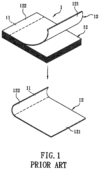
Sticky note pad
A sticky note pad includes a stack of note sheets.
US 9,944,340 B2 · Assignee: HONDA MOTOR CO., LTD. · Inventors: Kheawhorm; Sohnthaya et al.
Sheet 1 of 14 from the published document. All sheets in the USPTO PDF
To provide a LED headlight structure that visually conveys a modern or stylish appearance to an observer, the LED headlight structure is characterized in that: a headlight PCB( 260 ) low beam and high beam headlight LED structures on at least one side of the motorcycle are mounted to one plate or in one plane such that high beam illumination is emitted at the inside of the motorcycle and low beam illumination is emitted at the outside of the motorcycle; an extension member ( 120 ) is positioned forward of the reflector assembly ( 140 ) and between a headlight case ( 104 ) and a headlight lens ( 102 ); and a window structure ( 122 ) configured for selectively passing portions of the low and the high beam illumination reflected by the reflector assembly is formed at the extension member ( 120 ).
A number of modern motorcycles utilize Light Emitting Diodes (LED elements) to provide headlight illumination, particularly because LED elements offer higher brightness, lower power consumption, and a longer illumination lifetime compared to conventional light sources (e.g., halogen bulbs). Laid open Japanese patent publication JP 2010125898 describes a motorcycle having a headlight unit that uses LED elements to emit headlight illumination. As indicated in FIG. 5 of JP 2010125898, in this headlight unit a single LED is positioned on the left side of the motorcycle to provide left headlight illumination, and a single LED is positioned on the right side of the motorcycle to provide right headlight illumination. Such LEDs are mounted on a printed circuit board. Additionally, within the headlight unit a left side lens is disposed in front of the left side LED, and a right side lens is dispo
1 of 14 drawing sheets so far from the published document, cropped to the drawing. Every sheet is in the USPTO PDF.
What the patent claimed, word for word. All of it is now free to use.
This invention relates generally to a light emitting diode (LED) headlight structure for a motorcycle (e.g., a small motorcycle such as a scooter). The LED headlight structure includes a single circuit board that carries high beam and low beam LED elements on both sides (left side and right side) of the motorcycle, and a window structure that visually obscures or conceals the internal positions of the LED elements from an external observer, and which is shaped to convey a stylish (e.g., “slanted eyes”) headlight appearance to the observer.
A number of modern motorcycles utilize Light Emitting Diodes (LED elements) to provide headlight illumination, particularly because LED elements offer higher brightness, lower power consumption, and a longer illumination lifetime compared to conventional light sources (e.g., halogen bulbs). Laid open Japanese patent publication JP 2010125898 describes a motorcycle having a headlight unit that uses LED elements to emit headlight illumination. As indicated in FIG. 5 of JP 2010125898, in this headlight unit a single LED is positioned on the left side of the motorcycle to provide left headlight illumination, and a single LED is positioned on the right side of the motorcycle to provide right headlight illumination. Such LEDs are mounted on a printed circuit board. Additionally, within the headlight unit a left side lens is disposed in front of the left side LED, and a right side lens is disposed in front of the right side LED. However, it's not explicitly clear from this reference how the LED structure of this headlight unit is formed and shaped. DISCLOSURE/DESCRIPTION Technical Problem
JP 2010125898 teaches that the shape of its headlight unit looks like a one shape, conventional headlight body, which does not visually convey a new image for the LED headlight or the motorcycle. This reference further discloses the use of a lens positioned in front of each LED within the headlight unit. Because of the manner in which each lens is positioned relative to its corresponding LED, an observer viewing the front of the motorcycle of JP 2010125898 will readily identify the position of the LED elements inside of the headlight unit, and will visually perceive the LED elements like existing or conventional headlight bulbs. As a result, the visual appearance of this headlight unit is not new, and does not appear modern or stylish, notwithstanding the fact that this headlight unit is adapted to provide illumination by way of LED elements (e.g., to an observer looking at the front of the motorcycle of JP 2010125898, the appearance of the motorcycle's headlights may appear conventional and outdated).
Additionally, to provide high beam and low beam headlights on left and right sides of a motorcycle, four LED elements are required, namely,
a left side low beam LED;
a left side high beam LED;
a right side low beam LED; and
a right side high beam LED. In accordance with the LED headlight unit detailed in Japanese patent publication JP 2010125898, the provision of high beam and low beam headlights on right and left sides of the motorcycle requires that each of the four. LED elements is mounted to its own individual LED printed circuit board. In other words, two LED printed circuit boards are needed on each side of the motorcycle. Accordingly, such additional circuit boards increase the parts count, complexity, and cost of a motorcycle headlight structure.
It is desired to provide two headlight images on both sides of a motorcycle as LED-based headlights in a manner that visually conveys a modern or stylish appearance to an observer, which also provides an LED headlight assembly that reduces or minimizes parts count, complexity, and cost. Technical Solution
This invention according to claim 1 is a light emitting diode (LED) headlight structure for a motorcycle having headlight LED elements for emitting low beam and high beam illumination, a headlight printed circuit board (PCB) to which said headlight LED elements are mounted, a reflector assembly having low and high beam reflectors, configured to reflect said low beam and high beam illumination emitted by said headlight LED elements toward the front of the motorcycle, said LED headlight structure constructed by combining said headlight PCB with an upper portion of said reflector assembly, said LED headlight structure positioned within a space connecting a headlight case and a headlight lens, and mounted on both sides of motorcycle, characterized in that: said headlight PCB mounts at least said headlight LED elements on one side of the motorcycle to one plate or in one plane, said high beam illumination is emitted at the inside of the motorcycle and said low beam illumination is emitted at the outside of the motorcycle on one side of the motorcycle, an extension member is positioned forward of the reflector assembly and between said headlight case and said headlight lens, and a window structure is formed at said extension member, the window structure configured for passing portions of said low and high beam illumination reflected by the reflector assembly therethrough, wherein an upper border of said window structure is located close to an upper portion of the low beam reflector and is located below the high beam reflector, with respect to a front view of the motorcycle, and wherein the upper border of said window structure is oriented obliquely in a downward direction toward the inside of the motorcycle.
This invention according to claim 2 has, in the LED headlight structure of claim 1 , a characteristic in that the window structure is formed at both sides of the motorcycle and forms a generally rectangular shape expanding forward and to the outside of motorcycle, wherein at an inside border and an upper or lower border of said window structure the LED headlight structure further includes a light guide member that emits light.
This invention according to claim 3 has, in the LED headlight structure of claim 2 , a characteristic in that the light guide member emits light at two sides of the window structure and forms the lower border of the window structure.
This invention according to claim 4 has, in the LED headlight structure of claim 2 , a characteristic in that the LED headlight structure further includes light guide member LED elements, wherein a portion of the light guide member is positioned to receive light output by said light guide member LED elements, and wherein the light guide member on both sides of motorcycle is integrally formed (e.g., the light guide member integrally spans both sides of the motorcycle).
This invention according to claim 5 has, in the LED headlight structure of claim 4 , a characteristic in that the light guide member includes a connecting portion for connecting to both inside borders of light guide member, and a wherein single PCB to which said light guide member LED elements are mounted is positioned close to said connecting portion of the light guide member.
This invention according to claim 6 has, in the LED headlight structure of claim 5 , a characteristic in that the motorcycle includes a front cover that covers and surrounds portions of the LED headlight structure, and which covers said connecting portion of the light guide member, said light guide member LED elements, and said single PCB.
This invention according to claim 7 has, in the LED headlight structure of claim 2 , a characteristic in that said light guide member has the function of a position light structure of the motorcycle.
This invention according to claim 8 has, in the LED headlight structure of claim 1 , a characteristic in that said window structure is positioned at both sides of the motorcycle and forms a generally rectangular shape expanding forward and to the outside of motorcycle, and has light dispersion elements near an upper or lower border of said high beam reflector, wherein the light dispersion elements are configured to receive and scatter the light reflected by said reflector assembly.
This invention according to claim 9 has, in the LED headlight structure of claim 8 , a characteristic in that said light dispersion elements are disposed on a lower border of the window structure corresponding to the high beam reflector. Advantageous Effects
According to the invention disclosed in claim 1 , it's possible to provide a separated headlight image on both sides of motorcycle, and as the upper border of the window structure is formed to have an upper inclination to the outside of the motorcycle, it also possible to provide an “ends-up eye outline” (e.g., “slanted eyes”) visual image or appearance. After all, the motorcycle's appearance should be emphasized and produced to provide a distinctive, modern, strong, and sharp, sporty design. Furthermore, the headlight LED elements are mounted to a single headlight PCB for emitting low beam and high beam illumination toward a reflector assembly disposed below the headlight PCB. The use of a single headlight PCB reduces cost, structural complexity, and parts count. Additionally, because the upper border of the window structure at high beam reflector portion is positioned below the high beam LED elements, an observer looking toward the front of the motorcycle cannot readily determine the internal locations of the high beam LED elements within the LED headlight structure, which further aids the creation of a new and edgy design that provides a mysterious and attractive visual impression with no sight of the lighting source.
According to the invention disclosed in claim 2 , a single light guide member can provide illumination (e.g., position illumination) to both sides of the motorcycle. Furthermore, the light guide member can light portions of the high beam reflector when the high beam headlights are off during the motorcycle's usual running conditions. Accordingly, the light of the light guide member on two borders of the window structure can facilitate the optical communication of light to both sides during low beam LED illumination. As a result, low beam illumination is distributed more uniformly across reflecting surfaces provided by the reflector assembly and provides much better visibility than for other types of headlight structure designs from the perspective of other vehicle drivers (e.g., car drivers) and pedestrians.
According to the invention disclosed in claim 3 , the position of the light guide members along lower borders of the window structure further aids in the creation of a “slanted eyes” appearance having a sporty design that provides a strong visual impression because the low beam lighting portion expands forward and to the outside of motorcycle.
According to the invention disclosed in claim 4 , a single piece light guide member facilitates structural simplicity, reduced parts count, and reduced cost.
According to the invention disclosed in claim 5 , it's easy to form a light introduction portion on the light guide's connecting portion which can be aligned close to a single PCB on which the light guide member LED elements reside, thereby reducing PCB size and cost.
According to the invention disclosed in claim 6 , the motorcycle front cover overlays portions of the LED headlight structure in which the connecting portion of the light guide member, the light guide member LED elements, and the single PCB on which the light guide member LED elements are mounted, thereby concealing these overlaid elements from an observer looking toward the front of the motorcycle. These overlaid elements can be positioned between left and right windows of the window structure, and correspondingly between left and right reflectors of the reflector assembly, thereby efficiently utilizing what would otherwise be unutilized dead space and enhancing the compactness of the LED headlight assembly.
According to the invention disclosed in claim 7 , the light guide member is centrally lighted, with no relation to low or high beam headlight lighting, as a position light. Accordingly, it provides better motorcycle visibility, and is also expected to convey the feeling or impression of a new headlight design to others.
According to the invention disclosed in claim 8 , even under low beam illumination conditions when high beam LED elements are not on, the light dispersion elements facilitate the distribution of low beam illumination reflected by low beam reflectors to near upper or lower border portions of the high beam reflectors, without the need for additional active illumination sources. This reduces structural complexity, cost, and parts count, and it's possible to supply illumination corresponding to the light dispersion elements at portions between both sides of the low beam headlights.
According to the invention disclosed in claim 9 , the disposition of the light dispersion elements on the lower side of the window structure aids in the creation of a strong “slanted eyes” visual image having a sporty design because dispersion of light on the lower border of the window structure corresponds to and visually connects both sides of low beam lighting, which expands forward and to the outside of motorcycle.
FIG. 1 is a side view of a representative scooter type motorcycle having an LED headlight structure in accordance with an embodiment of the present disclosure.
FIG. 2 is a front view of the motorcycle of FIG. 1 in accordance with an embodiment of the present disclosure.
FIG. 3 is a partial magnified or zoomed-in front view of the motorcycle of FIG. 2 in accordance with an embodiment of the present disclosure.
FIGS. 4A and 4B are disassembled or exploded views of a motorcycle LED headlight structure in accordance with an embodiment of the present disclosure.
FIG. 5 is a front view showing a lighting unit mounted to a motorcycle LED headlight structure, which is disassembled from an outer lens, depicting an extension member, dashed line representations of elements disposed rearward of the extension member, and an inner lens in accordance with an embodiment of the present disclosure.
FIG. 6 is a representative left headlight low beam cross section (A-A′) through the motorcycle LED headlight structure of FIG. 5 .
FIG. 7 is a representative left headlight high beam cross section (B-B′) through the motorcycle LED headlight structure of FIG. 5 , which is disposed inwardly toward a central plane of the motorcycle relative to the left headlight low beam cross section of FIG. 6 .
FIG. 8 is a representative center cross section (C-C′) through the motorcycle LED headlight structure of FIG. 5 , which is disposed inwardly of each of the left headlight low beam cross section of FIG. 5 and the left headlight high beam cross section of FIG. 6 , and which is the same as a central plane of the motorcycle.
FIG. 9 is a top view of a motorcycle LED headlight structure in accordance with an embodiment of the present disclosure.
FIG. 10 is a second front view showing portions of the motorcycle LED headlight structure of FIG. 5 , only in the absence of an extension member in accordance with an embodiment of the present disclosure.
FIG. 11 is a third front view illustrating the motorcycle LED headlight structure of FIG. 10 , only in the absence of an inner lens in accordance with an embodiment of the present disclosure.
FIG. 12 is a front view of an extension member for a motorcycle LED headlight structure in accordance with an embodiment of the present disclosure.
FIG. 13 is a front view of an inner lens for a motorcycle LED headlight structure in accordance with an embodiment of the present disclosure.
FIG. 14 is a perspective view showing a headlight PCB, the position light PCB, and electrical couplings provided thereto in accordance with an embodiment of the present disclosure.
FIG. 1 is a left-side view of a motorcycle or motorbike 10 that includes a LED headlight structure 100 in accordance with an embodiment of the present disclosure. FIG. 2 is a full front view of the motorcycle 10 of FIG. 1 , and FIG. 3 is a zoomed-in partial front view of the motorcycle 10 of FIGS. 1 and 2 . In various embodiments, the motorcycle 10 is a motor scooter or a generally similar type of saddle-ride or straddle-ride type vehicle.
In the embodiment shown, the motorcycle 10 is a motor scooter equipped with a swing type engine unit 20 and having an underlying frame through which a rider/driver can step through, and a step floor 12 having an upper surface for supporting the rider's feet in a manner understood by one having ordinary skill in the art. The motorcycle 10 additionally includes a seat 14 for seating the rider and an optional passenger. A pair of pillion steps 16 L disposed on each side of the motorcycle can support the passenger's feet; and a grab rail 18 disposed behind the seat 14 at the rear of the motorcycle 10 is configured for grasping by the passenger's hand(s).
The motorcycle's engine unit 20 is positioned below the seat 14 . The engine unit 20 is swingably mounted to the motorcycle's frame, and is configured to generate a propulsion or driving force deliverable to a rear axle of the motorcycle 10 by way of a transmission, for instance, a Continuously Variable Transmission (CVT, such as a belt-CVT) that is disposed within a CVT case 22 . The engine unit 20 includes an air intake system connected to an air cleaner 21 , which filters and removes particulate matter from air prior to the delivery of filtered air into the engine unit 20 . The engine unit 20 additionally includes an exhaust port and exhaust pipe coupled to a muffler 24 , which reduces the engine unit's acoustic output by the engine unit 20 . While the motorcycle 10 includes an electronic mechanism (e.g., a starter motor) for starting the engine unit 20 , the motorcycle 10 typically additionally includes a kick start arm 26 connected to a kick start pedal 27 , by which the rider can manually supply rotation to the engine unit 20 such that an air-fuel mixture therein is ignited to start the engine.
A rear wheel 30 equipped circumferentially with a rear tire 31 is mounted to the motorcycle's rear axle, for communicating the engine unit's driving force to an underlying surface or ground plane 2 on which the motorcycle 10 can be driven (e.g., a paved roadway or other generally planar surface). A rear cushion 28 on the left side of the motorcycle absorbing the swing motion of a rear tire 31 by bumps and vibrations to provide improved ride and motorcycle handling characteristics while limiting the distance across which the engine unit 20 and the seat 14 are displaceable relative to each other. A rear fender 40 is disposed above the rear tire 31 and below and rearward of the seat 14 , for substantially preventing mud, debris, and water that has been picked up from the motorcycle's underlying surface 2 and directed upward and rearward as a result of rotation of the rear tire 31 from traveling above and behind the fender 40 .
The motorcycle 10 includes a pair of handle grips 35 L,R around which the rider places their left and right hands for pivotally rotating a handle bar at a center of a steering axis. Steering motion supplied to the handle bar in response to the rider's relative pivotal operation of a left handle grip 35 L and a right handle grip 35 R about the steering axis causes a front wheel 32 , and hence a front tire 33 that is circumferentially disposed thereabout, to turn in a left or right direction. The front wheel 32 is positioned between a pair of front forks that include a pair of front fork bottom casings 34 L,R corresponding to each fork, and which is connected to a steering stem that couples both front forks to the motorcycle's handle bar. A front fender 42 is positioned above the front tire 33 , to serve a corresponding purpose to that of the rear fender 40 .
A rear brake lever 36 is disposed in front of the left handle grip 35 L and a front brake lever 37 is disposed in front of the right handle grip 35 R, which respectively enable rider-selective activation and control of rear and front brakes. The right handle grip 35 R also operates a throttle grip to control an engine throttle by way of rider-selective circumferential motion of the right handle grip 35 R relative to the handle bar, in a manner readily understood by one having ordinary skill in the relevant art. A motorcycle horn switch is typically disposed proximate to the left handle grip 35 L for rider-selective activation of a motorcycle horn 38 that is mounted to the front of the motorcycle 10 in a manner shown in FIG. 2 . Additionally, left and right turn signal switches are disposed proximate to the left handle grips 35 L, respectively, for rider-selective activation of left and right winker bulbs 118 L, R that are disposed within a motorcycle LED headlight structure 100 in accordance with an embodiment of the present disclosure, as illustrated in FIGS. 2 and 3 , and which reside behind an outer lens 102 that is installed on a front surface of the motorcycle 10 above the front fender 42 in a manner indicated in FIG. 1 and FIG. 4A . In addition to the foregoing, left and right rear-view or back mirrors 44 L,R are positioned above the left and right handle grips 35 L,R, respectively.
The motorcycle 10 further includes a plurality of covers or cover members configured for concealing internal structural and mechanical portions of the motorcycle 10 , such as the motorcycle's underlying frame, and forming portions of the motorcycle's exterior surfaces. Such covers include a tail light cover 50 installed beneath the grab rail 18 , which surrounds portions of a tail light 46 configured for directing tail light illumination rearward and outward; left and right body covers 52 L,R, which are installed beneath the seat 14 and which project forward and downward toward the step floor 12 ; and a center cover 54 installed beneath frontal portions of the seat 14 , which extends to the left and right sides of the motorcycle 10 around the frontal portions of the seat 14 and downwardly toward the step floor 12 . Left and right floor covers 56 L,R are installed below the step floor 12 on left and right sides of the motorcycle 12 , respectively.
A lower inner cover 58 is installed forward of the seat 14 , such that the lower inner cover 58 is disposed forward (e.g., directly in front) of the rider's knees and shins, and a central section of the lower inner cover 58 is positioned between the rider's knees, when the rider is sitting on the seat 14 and the rider's feet are supported by the step floor 12 (e.g., when the rider is driving the motorcycle 10 ). A forward-rearward separation between (a) the lower inner cover 58 , and (b) the seat 14 plus the center cover 54 disposed beneath the seat 14 provides a spatial gap across or through which the rider can step.
Left and right lower front covers 60 L,R are installed forward of the floor cover 56 and the inner lower cover 58 , and extend upward along a portion of the inner lower cover's height. Left and right front covers 62 L,R are mounted above the lower front covers 60 L,R to form portions of the motorcycle's left and right front exterior side surfaces. The front covers 62 L,R upwardly extend from upper borders of the lower front covers 60 L,R to an upper border of the lower inner cover 58 . Portions of the front covers 62 L,R upwardly and forwardly extend higher than the front fender 42 .
Portions of the motorcycle's front exterior surface are formed by a front top cover 64 and an outer lens 102 of the motorcycle LED headlight structure 100 . The front top cover includes borders or edges that extend inwardly and downwardly toward a central plane or center line 5 of the motorcycle 10 , which divides the motorcycle 10 into substantially symmetric left and right halves. The front top cover 64 overlays portions of the motorcycle LED headlight structure 100 , including the outer lens 102 , such that a left side portion 103 L of the outer lens 102 resides to the left of the central plane 5 and a right side portion 103 R of the outer lens 102 resides to the right of the central plane 5 . The pair of side portions 103 R,L are integrally formed in the outer lens 102 in the manner shown in FIG. 4A , and the front top cover 64 overlays the portion between both side portions 103 R,L as shown FIG. 3 . In the embodiment shown in FIG. 1 , the front top cover 64 and the outer lens 102 establish a rearward and upward slant or slope along the motorcycle's front exterior surface (e.g., as viewed from the left or right side of the motorcycle 10 ). The motorcycle 10 also includes a front number plate stay (e.g., a front license plate retention structure) 65 mounted to an upper portion of the front top cover 64 .
An upper inner cover 66 is installed rearward of the front top cover 64 , above the lower inner cover 58 and directly forward of the rider. Above each of the front top cover 64 and the upper inner cover 66 , a front handle cover 68 is installed over forward facing portions of the motorcycle's handle bar, and a corresponding rear handle cover 69 is installed over rearward facing portions of the motorcycle's handle bar. Both handle covers 68 , 69 connect to cover the handle bar. The front handle cover 68 , as well as a forward portion of the front fender 42 , further provide a rearward and upward slant or slope along frontal surfaces of the motorcycle 10 . A meter 70 including a speedometer and having a meter cover 72 through which the rider can view the motorcycle's information including speed, is installed at an angled upper surface of the rear handle cover 68 .
In addition to the foregoing, a pair of front garnish portions 63 L,R form a frontal border of the motorcycle 10 above the left and right lower front covers 60 L,R, inside of the left and right front covers 62 L,R, and a front underside border below the front top cover 64 and the motorcycle LED headlight structure 100 . In this embodiment, the front garnish portions 63 L,R are integrally formed in the lower front cover 60 . The front fender 42 is positioned midway between a left border and a right border of the front garnish portions 63 L,R, and in the embodiment shown, portions of the motorcycle's horn 38 can be seen between a right edge of the front fender 42 and the right border of the front garnish portions 63 L,R. Finally, the motorcycle 10 includes a main stand 80 that can be pivoted into a support position for supporting the motorcycle 10 in a left-right symmetric upright position about its central plane 5 ; and a side stand 82 for supporting the motorcycle 10 at a small leftward tilt.
FIGS. 2 and 3 provide front views of the motorcycle 10 showing particular portions of the motorcycle LED headlight structure 100 that are disposed behind the outer lens 102 . As indicated in FIGS. 2 and 3 , the motorcycle LED headlight structure 100 provides a left headlight 110 L and a right headlight 110 R, each of which includes a set of reflectors configured for reflecting low beam LED illumination and high beam LED illumination toward, to, and through the headlight structure's outer lens 102 , into the motorcycle's external environment. More specifically, the left headlight 110 L includes a left low beam reflector 142 L and a left high beam reflector 144 L; and the right headlight 110 R includes a right low beam reflector 142 R and a right high beam reflector 144 R. In the embodiment shown, a given low beam reflector 142 L,R and its corresponding high beam reflector 144 L,R are disposed adjacent to each other, such that the high beam reflector 144 L,R is closest or next to the motorcycle's central plane 5 , and the low beam reflector 142 L,R is laterally disposed outward from its corresponding high beam reflector 144 L,R, away from the central plane 5 . Other low beam and high beam reflector configurations are possible in alternate embodiments.
The motorcycle LED headlight structure 100 further includes an extension member 120 that covers particular inner portions of the motorcycle LED headlight structure 100 . The extension member 120 includes left and right winker openings 128 L,R through which corresponding left and right winker bulbs 118 L,R are exposed. In the embodiment shown, the extension member 120 also includes left and right winker reflectors 129 L,R respectively corresponding to the left and right winker bulbs 118 L,R, and which are configured to reflect illumination output thereby in forward and sideward directions.
Additionally, the extension member 120 is comprised of or includes a headlight window structure 122 R,L through which portions of the LED illumination reflected by the left side and right side low beam and high beam reflectors 142 L,R, 144 L,R can pass along a travel path toward, to, and through the outer lens 102 . As described in detail below, the window structure 122 R,L forms a generally or approximately rectangular, rectangular, or multi-sided (e.g., four-sided) shape that selectively intercepts or blocks LED illumination reflected from certain portions of the left side and right side low beam and high beam reflectors 142 L,R, 144 L,R which are proximate to left side and right side low beam and high beam LED elements, such that the locations of the LED elements within the motorcycle LED headlight structure 100 cannot be easily or readily determined by an observer (e.g., the driver of an automobile or other vehicle, or a pedestrian) viewing the front of the motorcycle 10 . The window structure 122 R,L includes an upper border that is obliquely oriented in a downward direction on each of the motorcycle's left and right sides, toward the inside of the motorcycle, that is, toward the motorcycle's central plane 5 . As detailed below, the window structure's rectangular shape presents a distinctive, modern, and/or stylish left and right headlight shape having a strong visual impact or impression upon the observer.
In the embodiment shown, the window structure 122 includes a left window 122 L corresponding to the left side low beam and high beam reflectors 142 L, 144 L; and a right window 122 R corresponding to the right side low beam and high beam reflectors 142 R, 144 R. The spatial area of the left window 122 L defines a left LED headlight illumination output area; and the spatial area of the right window 122 R defines a right LED headlight illumination output area. Each of the left and right windows 122 L,R includes four borders or sides that reside along or define the window structure's outline or perimeter through which LED illumination can pass. Specifically, in the embodiment shown in FIGS. 4 and 5 , each of the left and right windows 122 L,R forms a shape having an inner side, edge, or border 124 , an upper side, edge, or border 125 , a lower side, edge, or border 126 , and an outer side, edge, or border 127 , where the inner border 124 is positioned closest to the motorcycle's central plane 5 . The borders 124 - 127 of each window 122 L,R are formed in a manner that provides the left and right headlights 110 L,R with a distinctive, modern, and/or stylish appearance to an observer, for instance, a “slanted eyes” appearance, as further elaborated upon below.
As also indicated in FIGS. 2 and 3 , the motorcycle LED headlight structure 100 includes a left position light or left position light structure 210 L and a right position light or right position light structure 210 R configured to emit left and right LED position illumination, respectively. Each position light structure 210 L,R linearly extends along a predetermined set of directions parallel or adjacent to particular borders of the window structure. In this embodiment, the left position light structure 210 L extends along portions of the left window's inner and lower borders 124 , 126 ; and the right position light structure 210 R extends along portions of the right window's inner and lower borders 124 , 126 . The position light structures 210 L,R provide motorcycle position lighting along and around portions of the left and right windows 122 L,R. The provision of position lighting in this manner impressively unifies LED headlight illumination and position illumination, in contrast to prior manners of providing position lighting. With respect to an observer's visual perception of illumination provided by the motorcycle LED headlight structure 100 , such an impressively unified arrangement of the left and right windows 122 L,R relative to their corresponding left and right position light structures 210 L,R establishes a strong, unified optical/visual association between LED headlight illumination and position illumination.
FIGS. 4A-14 illustrate internal aspects of a motorcycle LED headlight structure 100 in accordance with an embodiment of the present disclosure. As indicated in disassembled or exploded views of FIGS. 4A and 4B , the motorcycle LED headlight structure 100 includes the outer lens 102 ; a housing or case 104 ; and a lighting unit 106 that installs between the outer lens 102 and the housing 104 . The housing 104 is mountable to the front of the motorcycle 10 , for instance, by way of a plurality of mounting members or flanges 105 a - f having openings therein for receiving mounting fasteners such as bolts or screws as shown in FIGS. 4A and 5 . The lighting unit 106 is securable or mountable to the housing 104 , and the outer lens 102 is connectable or mountable to the lighting unit 106 and/or the housing 104 .
In this embodiment, the lighting unit 106 is configured for providing left and right high beam and low beam LED headlight illumination; left and right LED position illumination; and left and right winker illumination. LED headlight illumination and LED position light illumination is provided by a plurality of LED elements as described in detail below, which are typically white LED elements (e.g., LED elements that can output white light at suitable intensities for low beam LED headlight illumination, high beam LED headlight illumination, and position light LED illumination, in a manner understood by one having ordinary skill in the relevant art). During operation, left low beam and high beam LED headlight illumination, left LED position light illumination, and left winker illumination output by the lighting unit 106 travels through and beyond the left side portion 103 L of the outer lens 102 . Similarly, right low beam and high beam LED headlight illumination, right LED position light illumination, and right winker illumination output by the lighting unit 106 travels through and beyond the right side portion 103 R of the outer lens 102 .
With respect to the provision of LED headlight illumination and LED position illumination, as indicated in FIG. 4B the lighting unit 106 includes the following: (a) the extension member 120 and corresponding LED headlight illumination window structure(s) 122 , which in several embodiments are formed in the extension member 120 itself; (b) a reflector assembly 140 at which each of the left and right low beam and high beam reflectors 142 L,R, 144 L,R resides, and which is installed rearward of or behind the extension member 120 and the window structure(s) 122 ; and (c) a single headlight PCB 160 that carries a plurality of headlight LED elements including left and right low beam and high beam LED elements, which is mounted above the reflector assembly 140 such that low beam and high beam LED illumination emitted by the headlight LED elements (e.g., from holes formed above or at the upper portion of the reflector assembly 140 , not shown) is received by the low beam and high beam reflectors 142 L,R, 144 L,R and reflected thereby toward the window structures 122 ;
as well as (d) a position light PCB 260 that is attached forward of the reflector assembly 140 and behind the extension member 120 , and which carries a plurality of position light LED elements 264 L,R, 266 L,R; (e) an inner lens 202 having a plurality of light guide members 204 L,R, 206 L,R corresponding to the left and right position light structures 210 L,R; and (f) an inner lens mating structure 130 formed in a central and lower portion of the extension member 120 , which is configured to receive the inner lens 202 , and align with the position light PCB 260 such that the inner lens light guide members 204 L,R, 206 L,R receive light emitted by the position light LED elements 264 LR, 266 L,R.
Direct current (DC) electrical power is provided to the headlight PCB 160 and the position light PCB 260 , and hence to the plurality of headlight LED elements and the plurality of position light LED elements 264 LR, 266 L,R, by way of a single PCB electrical connector 190 that is connectable (e.g., switchably connectible/conductible, by way of motorcycle ignition key position selections) to the motorcycle's battery.
As described in detail hereafter, the manner in which lighting unit elements are spatially coordinated or cooperatively arranged relative to each other, in association with structural features provided by particular lighting unit elements, distributes low beam and high beam LED headlight illumination with enhanced evenness across the illumination output area of each of the left and right headlights 110 L,R, and additionally visually obscures or conceals the positions of the headlight LED elements inside the motorcycle LED headlight structure 100 from an observer looking toward the front of the motorcycle 10 (e.g., an observer who sees the motorcycle 10 approaching within their forward field of view).
FIGS. 5-14 provide various corresponding or counterpart views showing internal structural details of the motorcycle LED headlight structure 100 in accordance with an embodiment of the present disclosure, which are referenced in combination with each other in the description that follows for purpose of brevity and to aid understanding. FIGS. 5 and 9-11 provide particular front views of portions of the motorcycle LED headlight structure 100 . More specifically, FIG. 5 is a front view showing elements within the motorcycle LED headlight structure 100 disposed behind the outer lens 102 , which illustrates the extension member 120 , dashed-line representations of elements, especially the reflector assembly 140 disposed behind the extension member 120 , and the inner lens 202 . FIG. 10 is a second front view counterpart of FIG. 5 , which illustrates elements of the lighting unit 106 without the extension member 120 ; and FIG. 11 is a third front view counterpart of FIG. 5 , which illustrates elements of the lighting unit 106 without the extension member 120 and without the inner lens 202 . FIGS. 6-8 provide cross sectional views through normal planar sections corresponding to lines A-A′, B-B′, and C-C′ identified in FIG. 5 , respectively corresponding to planar sections through left low beam, left high beam, and central portions of the motorcycle LED headlight structure 100 . Additionally, FIG. 9 provides a top view showing portions of the motorcycle LED headlight structure 100 . Finally, FIG. 12 is a front view of the extension member; FIG. 13 is a front view of the inner lens 202 ; and FIG. 14 is a perspective view of the headlight PCB 160 , the position light PCB 260 , and electrical couplings associated therewith.
With reference again to FIGS. 4A-4B and further reference to FIG. 5 , FIG. 9 , and FIG. 12 , the extension member 120 forms significant portions of the lighting unit's frontal or forward facing surface. In the embodiment shown, the extension member 120 provides multiple apertures or windows therein, including the left and right winker openings 128 L,R within which the left and right winker bulbs 118 L,R are disposed; and the windows 122 L,R through which left and right low beam and high beam LED illumination is output from the lighting unit 106 in forward directions.
The description continues in the full USPTO document.
About 6,759 words. The USPTO PDF has it with every drawing.
Fees are due 3.5, 7.5 and 11.5 years after grant. This patent expired on April 17, 2026, so the fee marked "not paid" was the one that went unpaid.
LED HEADLIGHT STRUCTURE FOR MOTORCYCLE
Filed Oct 2013 · published Aug 2016LED headlight structure for motorcycle
Filed Oct 2013 · granted Apr 2018Earlier publications, parents and continuations. None of them can still be enforced, or this patent would not be listed.
Prior art cited by the examiner or applicant. Useful when you check your own idea for novelty.
Everything on this page comes from the documents linked above.


