 Lapsed, fee not paid5 drawings
Industrial Equipment · US 9,944,081 B2
Cleaning adapter and method for cleaning print heads
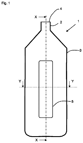
A cleaning adapter cleans print heads in an installation for the printing of containers.
US 9,944,092 B2 · Assignee: Ricoh Company, Ltd. · Inventors: Nagasawa; Satoru
Sheet 1 of 15 from the published document. All sheets in the USPTO PDF
A post-processing agent application control device includes: a first post-processing agent application amount determination unit configured to determine an amount of a post-processing agent to be applied to an image formed on a recording medium; a first glossiness determination unit configured to determine a first glossiness that is a glossiness of a non-image area of the recording medium in a case where the determined amount of the post-processing agent is applied to the non-image area; and a second post-processing agent application amount determination unit configured to, if glossiness difference between the determined first glossiness and a second glossiness that is a glossiness of the non-image area of the recording medium is applied is larger than the predetermined value, change an amount of the post-processing agent to be applied, in a stepwise manner from an image area to the non-image area.
In recent years, image forming apparatuses that are used to output computerized information or to copy originals have been necessary devices. Among those image forming apparatuses, image forming apparatuses configured to apply a post-processing agent to the printed surface of a printed matter after printing are known. With respect to such image forming apparatuses, it is necessary to reduce the amount of a post-processing gent to be applied in order to reduce the cost per page (CPP) and increase the dryness. A technique of applying a post-processing agent to only a printed area is already known (see Japanese Unexamined Patent Application Publication No. 2014-176997). In the case where the post-processing agent is applied to only the printed area as with the image forming apparatus disclosed in Japanese Unexamined Patent Application Publication No. 2014-176997, the post-processing agent m
8 of 15 drawing sheets so far from the published document, cropped to the drawing. Every sheet is in the USPTO PDF.
What the patent claimed, word for word. All of it is now free to use.
The present application claims priority under 35 U.S.C. § 119 to Japanese Patent Application No. 2016-006538, filed Jan. 15, 2016 and Japanese Patent Application No. 2016-226075, filed Nov. 21, 2016. The contents of which are incorporated herein by reference in their entirety.
The embodiments discussed herein are directed to a post-processing agent application control device, an image forming system, a post-processing agent application control method, and a recording medium.
In recent years, image forming apparatuses that are used to output computerized information or to copy originals have been necessary devices. Among those image forming apparatuses, image forming apparatuses configured to apply a post-processing agent to the printed surface of a printed matter after printing are known.
With respect to such image forming apparatuses, it is necessary to reduce the amount of a post-processing gent to be applied in order to reduce the cost per page (CPP) and increase the dryness. A technique of applying a post-processing agent to only a printed area is already known (see Japanese Unexamined Patent Application Publication No. 2014-176997).
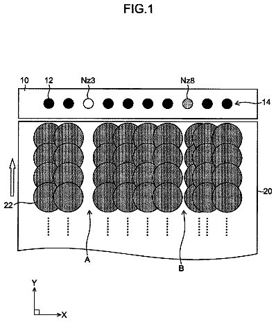
In the case where the post-processing agent is applied to only the printed area as with the image forming apparatus disclosed in Japanese Unexamined Patent Application Publication No. 2014-176997, the post-processing agent may be applied to a shifted position from the printed area depending on the printing accuracy, the accuracy in applying the post-processing agent, and the accuracy in conveying a recording medium. In other words, the post-processing agent may be not necessarily applied to an area to which the post-processing agent is required to be applied. In order to prevent this, it is necessary, when the technique disclosed in Japanese Unexamined Patent Application Publication No. 2014-176997 is used, to apply the post-processing agent to an area wider than the printed area in consideration of the accuracy listed above.
When the post-processing agent is applied to an area wider than the printed area, however, there is a problem in that the post-processing agent is partly applied also to an area other than the printed area (hereinafter, referred to as an “unprinted area”) and accordingly a difference in glossiness occurs at the boundary between the unprinted area to which the post-processing agent is applied (hereinafter, “application area”) and the unprinted area to which the post-processing agent is not applied (hereinafter, “non-application area).
According to one aspect of the present invention, a post-processing agent application control device is configured to control application of a post-processing agent to a recording medium by a post-processing agent application device. The post-processing agent application control device includes a first post-processing agent, a first glossiness determination unit, a comparison unit, and a second post-processing agent application amount determination unit. The first post-processing agent application amount determination unit is configured to determine an amount of the post-processing agent to be applied to an image formed on the recording medium. The first glossiness determination unit is configured to determine a first glossiness that is a glossiness of a non-image area of the recording medium in a case where the determined amount of the post-processing agent is applied to the non-image area. The comparison unit is configured to compare a glossiness difference between the determined first glossiness and a second glossiness that is a glossiness of the non-image area of the recording medium is applied, with a predetermined value. The second post-processing agent application amount determination unit is configured to, if the glossiness difference is larger than the predetermined value, change an amount of the post-processing agent to be applied, in a stepwise manner from an image area to the non-image area.
FIG. 1 is an overview (schematic side view) of an exemplary image forming apparatus according to an embodiment of the present invention;
FIG. 2A is a schematic view of an exemplary configuration of an array of droplet ejection heads of an image forming unit and a post-processing liquid application unit according to the embodiment of the invention;
FIG. 2B is an enlarged view of a part of FIG. 2A ;
FIG. 3A is a bottom view for explaining a case where a line head is used as an exemplary image forming unit and an exemplary post-processing ejection unit of the image forming apparatus illustrated in FIG. 1 ;
FIG. 3B is an enlarged view of FIG. 3A ;
FIG. 4A is a schematic diagram of an exemplary image forming system according to the embodiment of the invention;
FIG. 4B is a schematic configuration diagram of an exemplary higher-level device according to the embodiment of the invention;
FIG. 5 is a functional block diagram of an image forming apparatus according to the embodiment of the invention;
FIG. 6 is a functional block diagram illustrating an exemplary data manager of a control unit according to the embodiment of the invention;
FIG. 7 is a functional block diagram illustrating an exemplary image output performed by the control unit according to the embodiment of the invention;
FIG. 8 is a flowchart of exemplary operations of the image forming apparatus according to the embodiment of the invention;
FIGS. 9A and 9B are views for explaining a method of applying a post-processing liquid performed by a post-processing liquid application unit according to the embodiment of the invention;
FIG. 10 is a diagram for explaining a process performed by the image forming apparatus to determine the amount of the post-processing liquid to be applied according to the embodiment of the invention;
FIG. 11 is a diagram of an exemplary post-processing liquid application amount determination table according to the embodiment of the invention;
FIG. 12 is a diagram of an exemplary unprinted-area glossiness determination table according to the embodiment of the invention;
FIG. 13 is a diagram of another exemplary unprinted-area glossiness determination table according to the embodiment of the invention;
FIG. 14 is a diagram of an exemplary natural glossiness determination table according to the embodiment of the invention;
FIG. 15 is a diagram of an exemplary application area glossiness determination table according to the embodiment of the invention;
FIG. 16 is a functional block diagram of a functional configuration of a control unit of an higher-level device according to the embodiment of the invention; and
FIG. 17 is a functional block diagram of a functional configuration of a control unit of a printer device according to the embodiment of the invention.
The accompanying drawings are intended to depict exemplary embodiments of the present invention and should not be interpreted to limit the scope thereof. Identical or similar reference numerals designate identical or similar components throughout the various drawings.
The terminology used herein is for the purpose of describing particular embodiments only and is not intended to be limiting of the present invention.
As used herein, the singular forms “a”, “an” and “the” are intended to include the plural forms as well, unless the context clearly indicates otherwise.
In describing preferred embodiments illustrated in the drawings, specific terminology may be employed for the sake of clarity. However, the disclosure of this patent specification is not intended to be limited to the specific terminology so selected, and it is to be understood that each specific element includes all technical equivalents that have the same function, operate in a similar manner, and achieve a similar result.
An embodiment of the present invention will be described in detail below with reference to the drawings.
An embodiment has an object to reduce the difference in glossiness at the boundary between the area to which the post-processing agent is applied and the area to which the post-processing agent is not applied.
An image forming apparatus 100 according to the embodiment of the invention will be described with reference to FIGS. 1 to 3 . The image forming apparatus 100 includes ejection heads corresponding to four colors of black (K), cyan (C), magenta (M) and yellow (Y). Image forming apparatuses to which the invention is applicable are not limited to those including these ejection heads. In other words, image forming apparatuses to which the invention is applicable include an image forming apparatus that further includes ejection heads corresponding to green (G), red (R) and light cyan (LC) and/or another color (other colors) and an image forming apparatus that includes an ejection head corresponding to only black (K). In the following descriptions, “K, C, M and Y” used as indices of reference numerals are used to represent the colors of black, cyan, magenta and yellow, respectively.
In the embodiment, a continuous sheet of the roll of paper (hereinafter, “paper-roll sheet Md”) is used as a recording medium; however, recording media on which the image forming apparatus can form images are not limited to paper-roll sheets. In other words, recording media on which the image forming apparatus can form images may be cut paper sheets. Recording media on which the image forming apparatus can form images include normal paper sheets, high-quality paper sheets, thin paper sheets, thick paper sheets, recording paper sheets and paper-roll sheets and further include OHP sheets, synthetic resin films, metal thin films and sheet-type recording media each having a certain surface on which an image can be formed with, for example, ink.
The paper-roll sheet is a continuous sheet of paper longer than a standard size. The paper-roll sheet includes a continuous sheet of paper with perforations along which the paper sheet can be cut and that are formed at given intervals and a continuous sheet of paper without perforations. When ledger sheets are formed using a continuous paper sheet on which perforations are formed, a page of the ledger sheets is formed of the area between sets of perforations.
1. Configuration of Image Forming Apparatus 100
As illustrated in FIG. 1 , the image forming apparatus 100 according to the embodiment of the invention includes an conveying-in unit 10 , a pre-processing liquid application unit 20 , a pre-processing liquid drying unit 31 , an image forming unit 40 , a post-processing liquid application unit 50 that includes a post-processing agent application device, an permeation unit 55 , a post-processing liquid drying unit 32 , and an conveying-out unit 60 . The conveying-in unit 10 conveys the paper-roll sheet Md that is a recording medium into the image forming apparatus 100 . The pre-processing liquid application unit 20 applies a pre-processing liquid to the paper-roll sheet Md conveyed into the image forming apparatus 100 . The pre-processing liquid application unit 20 is a pre-processing unit that performs application of the pre-processing liquid to the paper-roll sheet Md as the pre-processing. The pre-processing liquid drying unit 31 that is a type of a drying unit 30 dries the paper-roll sheet Md having undergone the pre-processing. The image forming unit 40 forms an image on the surface of the paper-roll sheet Md on which the pre-processing liquid has been applied. The post-processing liquid application unit 50 applies a post-processing liquid that is a type of a post processing agent to the paper roll sheet Md with the image formed thereon. The post-processing liquid application unit 50 is a post-processing unit that performs application of the post processing liquid to the paper-roll sheet Md as the post processing. The permeation unit 55 causes droplets on the paper-roll sheet Md to permeate the paper roll sheet Md. The post-processing liquid drying unit 32 that is a type of the drying unit 30 dries the ink and the post-processing liquid on the paper-roll sheet Md. The conveying-out unit 60 rolls up the paper-roll sheet Md and conveys the paper-roll sheet Md out of the image forming apparatus 100 . The image forming apparatus 100 further includes a control unit 70 that controls operations of the image forming apparatus 100 as described below.
The components of the image forming apparatus 100 according to the embodiment of the present invention will be described below. The image forming apparatus 100 may be configured not to include at least any one of the pre-processing liquid application unit 20 , the drying unit 30 (the pre-processing liquid drying unit 31 and the post-processing liquid drying unit 32 ) and the permeation unit 55 .
2. Configuration of Conveying-In Unit 10
The conveying-in unit 10 is a unit that conveys the paper-roll sheet Md into the pre-processing liquid application unit 20 , etc. The conveying-in unit 10 includes, for example, a paper feeder 11 and multiple conveying rollers 12 . The conveying-in unit 10 uses the conveying rollers 12 , etc., to move the paper-roll sheet Md, which is rolled and held around a paper-feeding roll of the paper feeder 11 , toward the pre-processing liquid application unit 20 that is arranged downstream in the direction in which the paper-roll sheet Md is conveyed.
3. Configuration of Pre-Processing Liquid Application Unit 20
The pre-processing liquid application unit 20 is a unit that performs processing on the paper-roll sheet Md before an image is formed. The pre-processing liquid application unit 20 is a unit that performs pre-processing using the pre-processing liquid on the surface of the paper roll M that is conveyed into the pre-processing liquid application unit 20 by the conveying-in unit 10 .
The pre-processing according to the embodiment is processing of uniformly applying the pre-processing liquid having a function of solidifying the ink on the surface of the paper-roll sheet Md. The pre-processing allows the image forming apparatus 100 to effectively solidify the ink on the surface of the paper-roll sheet Md even when an image is formed on a paper-roll sheet Md other than a paper-roll sheet dedicated to the inkjet system.
4. Configuration of Pre-Processing Liquid Drying Unit 31
As illustrated in FIG. 1 , the image forming apparatus 100 includes the drying unit 30 that includes the pre-processing liquid drying unit 31 that dries the paper-roll sheet Md having undergone the pre-processing performed by the pre-processing liquid application unit 20 and the post-processing liquid drying unit 32 that dries the paper-roll sheet Md having undergone the post-processing performed by the post-processing liquid application unit 50 . The drying unit 30 is a unit that evaporates the moisture that is a solvent of the pre-processing liquid by, for example, heating the paper-roll sheet Md, thereby drying the paper-roll sheet Md.
The pre-processing liquid drying unit 31 includes multiple heat rollers. Each of the heat rollers is heated to, for example, 80° C. to 100° C. and is arranged such that each of the heat rollers makes contact with the back surface of the paper-roll sheet Md. A fan heater may be added to the pre-processing liquid drying unit 31 .
5. Configuration of Image Forming Unit 40
The image forming unit 40 is a unit that forms an image on the paper-roll sheet Md. The image forming unit 40 ejects the ink on the paper-roll sheet Md dried by the pre-processing liquid drying unit 31 to form an image on the surface of the paper-roll sheet Md.
An exemplary outer shape of the image forming unit 40 will be described with reference to FIG. 2 . FIG. 2A is a schematic plane view of an exemplary entire configuration of the image forming unit 40 of the image forming apparatus 100 according to the embodiment of the invention. FIG. 2B is an enlarged plane view of an exemplary election head 40 K corresponding to black (K) that is one of the components of the image forming unit 40 .
As illustrated in FIG. 2A , the image forming unit 40 includes a full-line head. The full-lined head includes four ejection heads 40 K, 40 C, 40 M and 40 Y that correspond to black (K), cyan (C), magenta (M) and yellow (Y), respectively, and that are arranged from the upstream in a direction Xm in which the paper-roll sheet Md is conveyed.
The ejection head 40 K corresponding to black (K) includes four head units 40 K- 1 , 40 K- 2 , 40 K- 3 and 40 K- 4 that are arranged in a zigzag manner in the direction orthogonal to the direction Xm in which the paper-roll sheet Md is conveyed. Accordingly, the image forming unit 40 is able to form an image over an image forming area of the paper-roll sheet Md in the width direction. In other words, the image forming unit 40 uses, as a printing area, the entire area in the direction orthogonal to the direction in which the paper-roll sheet Md is conveyed and forms an image on the printing area.
As illustrated in FIG. 2B , the head unit 40 K- 1 includes multiple nozzles 40 N on the nozzle surface (the outer surface of a nozzle plate 43 ). The multiple nozzles 40 N are ejection ports for ink that is a liquid and are areas referred to as printing nozzles. The nozzles 40 N constitute the nozzle array including multiple nozzles that are arranged in a line in the longitudinal direction of the head unit 40 K- 1 . The head unit 40 K- 1 employs a single-path inkjet system including a nozzle array in the main-scanning direction. The head unit 40 K- 1 may include multiple nozzle arrays.
The detailed configuration of the ejection head 40 K of the image forming unit 40 will be described here. As illustrated in FIG. 3A , the ejection head 40 K includes a flow-path plate 41 that forms a path for the ink to be ejected, an diaphragm 42 that is adhered to the bottom surface of the flow-path plate 41 (inner direction of the ejection head 40 K), the nozzle plate 43 that is adhered to the upper surface of the flow-path plate 41 (outer direction of the ejection head 40 K), and a frame member 44 that holds the periphery of the diaphragm 42 . The ejection head 40 K further includes a pressure generator 45 that is an actuator for deforming the diaphragm 42 .
In the ejection head 40 K according to the embodiment, the flow-path plate 41 , the diaphragm 42 and the nozzle plate 43 are laminated to form a nozzle communication path 40 R that is a flow path communicating with the nozzle 40 N and a liquid chamber 40 F. In the ejection head 40 K, the frame member 44 is further laminated and accordingly an ink flow-in port 40 S for supplying ink to the liquid chamber 40 F and a common liquid chamber 40 L that supplies ink to the liquid chamber 40 F are formed.
In the frame member 44 , a housing that stores the pressure generator, a concave area serving as the common liquid chamber 40 L, and an ink supply port 40 IN for supplying ink from the outside of the ejection head to the common liquid chamber 40 L are formed.
The pressure generator 45 includes a piezoelectric element 45 P that is an electromechanical transducer, a base substrate 45 B to which the piezoelectric element 45 P is fixed by adhesion, and a column arranged in the space between adjacent piezoelectric elements 45 P. The pressure generator 45 further includes a FPC cable 45 C for connecting the piezoelectric element 45 P to a drive circuit.
FIG. 3B is an enlarged diagram of a part of the piezoelectric element 45 P. As illustrated in FIG. 3B , for the piezoelectric element 45 P, a laminated piezoelectric element (PZT) in which a piezoelectric material 45 Pp and an internal electrode 45 Pe are laminated alternately. The internal electrode 45 Pe includes multiple individual electrodes 45 Pei and multiple common electrodes 45 Pec. The internal electrode 45 Pe is configured by connecting the individual electrode 45 Pei or the common electrode 45 Pec to the end surface of the piezoelectric material 45 Pp alternately.
An operation of the ejection head 40 K to eject the ink from the nozzles 40 N (pull-push operation) will be specifically described below.
In the ejection head 40 K, first of all, the voltage applied to the piezoelectric element 45 P that the pressure generator 45 includes is reduced from the reference potential to cause the piezoelectric element 45 P to shrink in its lamination direction. The shrink of the piezoelectric element 45 P causes deflection of the diaphragm 42 . The deflection of the diaphragm 42 increases the capacity of the liquid chamber 40 F of the ejection head 40 K. In other words, lowering the voltage applied to the piezoelectric element 45 P from the reference potential increases the volume of the liquid chamber 40 F. The series of operations causes the ink to flow from the common liquid chamber 40 L into the liquid chamber 40 F in the ejection head 40 K.
The voltage applied to the piezoelectric element 45 P of the ejection head 40 K is then increased to a voltage above the reference potential to cause the the piezoelectric element 45 P to extend in its lamination direction. The extension of the piezoelectric element 45 P deforms the diaphragm 42 in the direction to the nozzle 40 N. The deformation of the diaphragm 42 reduces the capacity of the liquid chamber 40 F. In other words, increasing the voltage applied to the piezoelectric element 45 P to a voltage above the reference potential reduces the volume of the liquid chamber 40 F. The series of operations applies a pressure to the ink in the liquid chamber 40 F in the ejection head 40 K. The pressure applied to the ink in the ejection head 40 K causes the ink to be ejected from the nozzles 40 N.
The ejection head 40 K then returns the voltage applied to the piezoelectric element 45 P to the reference potential. Accordingly, the diaphragm 42 returns to the initial position and restored. In the ejection head 40 K, the inner pressure of the liquid chamber 40 F decreases due to the expansion of the liquid chamber 40 F and accordingly the ink is supplied from the common liquid chamber 40 L to the liquid chamber 40 F and the liquid chamber 40 F is filled with the ink. After the oscillation of the meniscus surface of the nozzles 40 N attenuates and is stabilized, the ejection head 40 K moves to an operation for the next ejection. The ejection head 40 K repeats the operations described above.
As described above, using the pressure generator 45 , the ejection head 40 K causes deflection of the diaphragm 42 , changes the capacity of the liquid chamber 40 F, changes the pressure applied to the ink in the liquid chamber 40 F, and accordingly ejects the ink from the nozzles 40 N.
The method of driving the ejection head 40 K to which the invention is applicable is not limited to the above example (pull-push operation). For example, the method of driving the ejection head 40 K may be a pulling operation or a pushing operation that is performed by controlling the voltage (drive waveform) that is applied to the piezoelectric element 45 P. Furthermore, for the pressure generator 45 , a thermal type that heats the ink in the liquid chamber 40 F using a heating resistor to generate bubbles or an electrostatic type in which a diaphragm and an electrode are arranged on the wall surfaces of the liquid chamber 40 F such that the diaphragm and the electrode are opposed to each other and the diaphragm is deformed by the electrostatic force that is generated between the diaphragm and the electrode. Other ejection heads that are the ejection heads 40 C, 40 M and 40 Y have the same configuration as the ejection head 40 K corresponding to black (K). Thus, detailed descriptions thereof will be omitted.
In the above-described manner, the image forming apparatus 100 of the embodiment forms a black and white image or a full-color image over the image forming area using the image forming unit 40 (the four ejection heads 40 K, 40 C, 40 M and 40 Y) through the operation of conveying the paper-roll sheet Md once.
6. Configuration of Post-Processing Liquid Application Unit
The post-processing liquid application unit 50 is a unit that performs processing on the paper-roll sheet Md with an formed thereon. The post-processing liquid application unit 50 is a unit that performs the post-processing using the post-processing liquid on the surface of the paper-roll sheet Md with the image formed thereon by the image forming unit 40 . As illustrated in FIG. 2A , the post-processing liquid application unit 50 is arranged on the downstream side with respect to the image forming unit 40 in the direction in which the paper-roll sheet Md is conveyed. In the post-processing liquid application unit 50 , as in the case of the image forming unit 40 , an ejection head 50 H includes head units that are arranged in a zigzag manner in the direction orthogonal to the direction Xm in which the paper-roll sheet Md is conveyed.
The post-processing liquid application unit 50 controls the drive waveform that is input to the ejection head 50 H to control the amount of the post-processing liquid. In other words, the image forming unit 40 uses, as the printing area, the entire area in the direction orthogonal to the direction in which the paper-roll sheet Md is conveyed and forms an image on the printing area. The post-processing liquid application unit 50 is able to eject the post-processing liquid over the image forming area of the paper-roll sheet Md in the width direction using the ejection head 50 H. In other words, the post-processing liquid application unit 50 applies the post-processing liquid to the printing area that is the entire area in the direction orthogonal to the direction in which the paper-roll sheet Md is conveyed. The ejection head 50 H has the same configuration as the ejection head 40 K of the image forming unit 40 that is described with reference to FIGS. 2 and 3 . The detailed configuration of the ejection head 50 H will be omitted as it is possible to obtain descriptions thereof by properly reading the configuration of the ejection head 40 K as the configuration of the ejection head 50 H.
The post-processing according to the embodiment is processing of ejecting the post-processing liquid to the printing area on the paper-roll sheet Md and depositing the post-processing liquid. This post-processing makes it possible to prevent the ink from delaminating due to abrasion of the surface of the paper-roll sheet Md with the image formed thereon with another object, such as the other surface of the paper-roll sheet. In other words, the post-processing makes it possible to increase the rub resistance or the rubfastness of the printed image. The post-processing further makes it possible to increase the glossiness on the printed surface, preservation stability, etc. The preservation stability includes water resistance, light resistance, and gas resistance.
7. Configuration of Permeation Unit
The permeation unit 55 is a unit that permeates the solvent in the ink into the paper-roll sheet Md. The permeation unit 55 increases the distance in which the paper-roll sheet Md is conveyed to increase the time for permeation of the solvent. Furthermore, the heating unit 56 illustrated in FIG. 1 sets the temperature of the atmosphere in the permeation unit 55 at a temperature from 30° C. to 100° C. at which the moisture does not evaporate and heats the paper-roll sheet Md and the ink. Accordingly, the viscosity of the ink in the state of a solution containing the high-boiling-point solvent in the ink is lowered and the rate of permeation is increased.
8. Configuration of Post-Processing Liquid Drying Unit 32
As illustrated in FIG. 1 , the post-processing liquid drying unit 32 includes multiple heat rollers. Each of the heat rollers is heated to, for example, a temperature from 80° C. to 100° C. and is arranged such that each of the heat rollers makes contact with the back surface of the paper-roll sheet Md. A fan heater may be added to the post-processing liquid drying unit 32 . The post-processing liquid drying unit 32 is a unit that evaporates the moisture that is the solvent of the ink and the post processing liquid to dry the paper-roll sheet Md.
9. Configuration of Conveying-Out Unit 60
The conveying-out unit 60 is a unit that conveys the paper-roll sheet Md with the image formed thereon out of the image forming apparatus 100 . As illustrated in FIG. 1 , the conveying-out unit 60 includes a storage unit 61 and multiple conveying rollers 62 . The conveying-out unit 60 rolls the paper-roll sheet Md with the image formed thereon around a storage roll of the storage unit 61 using the conveying rollers 62 , etc., and stores the paper-roll sheet Md.
When the paper-roll sheet Md is rolled around the storage roll of the storage unit 61 , the pressure applied to the paper-roll sheet Md increases, which may highly likely increase the possibility that another image is transferred onto the back surface of the paper-roll sheet Md. In order to prevent the transfer of the image onto the back surface of the paper-roll sheet Md, a drying unit that further dries the paper-roll sheet Md just before the paper-roll sheet Md is rolled around the storage roll.
10. Configuration of Control Unit 70
The control unit 70 is a unit that has a configuration equivalent to a computer and executes a program that is stored in a storage unit with an operation processor to control operations of the image forming apparatus 100 . In the embodiment, the control unit 70 instructs each component of the image forming apparatus 100 to operate and controls the operation of each component. The control unit 70 according to the embodiment will be described with reference to FIGS. 4 to 7 .
The image forming apparatus 100 according to the embodiment of the invention may be used as a printing system for production printing. The production printing is a type of an image forming system that is a production system that makes it possible to print, for example, images on a large number of image forming media in a short time by efficiently managing jobs and print data. Specifically, the image forming apparatus 100 according to the embodiment includes multiple devices, such as a raster image processor (RIP) device and a printer. The RIP device is a device that controls the procedure for printing print data and converts the print data into raster image data. The printer is a control device that controls printing operations based on the converted raster image data.
The image forming apparatus 100 according to the embodiment is able to construct a workflow system that manages a workflow from creation of print data to distribution of printed matters. In other words, in the image forming apparatus 100 according to the embodiment, the devices, such as the RIP device and the printer, are separated in the system where the processing time is long as can be seen in this workflow to divide the processes, which enables faster printing.
FIG. 4A is a schematic diagram of an exemplary image forming system according to the embodiment of the invention and FIG. 4B is a schematic configuration diagram of an exemplary higher-level device.
As illustrated in FIG. 4A , the image forming system according to the embodiment of the invention may divide the control unit 70 of the image forming apparatus 100 into an higher-level device (a RIP device, a DFE and a Digital FrontEnd) 71 that performs RIP processing, etc., and a printer apparatus 72 that performs print processing, etc. The higher-level device 71 and the printer apparatus 72 are connected to each other with multiple lines that are a data line 70 LD and a control line 70 LC. The data line 70 LD is a data bus that is used to transmit print image data from the higher-level device 71 to the printer apparatus 72 . The control line 70 LC is a control bus for communicating print information data between the higher-level device 71 and a printer controller 72 C of the printer apparatus 72 .
Higher-Level Device 71
The higher-level device 71 corresponding to a part of the control unit 70 of the image forming apparatus 100 according to the embodiment of the invention is a device that performs the RIP processing on the basis of the print job data (job data and print data) that is output from a host device that issues an instruction on the content of the print processing to the image forming apparatus 100 . In short, the higher-level device 71 according to the embodiment generates each set of print image data corresponding to each color on the basis of the print job data. The print image data according to the embodiment contains the “image data on the post processing” regarding ejection of the post-processing liquid that is ejected by the post-processing liquid application unit 50 .
The higher-level device 71 according to the embodiment creates control information data for controlling printing operations on the basis of the print job data, the information of the host device, etc. The control information data contains, as printing conditions, data on a printing mode, a print type, paper feeding and ejection information, a printing surface order, a print paper size, a data size of print image data, a resolution, paper type information, gradation, color information and information, such as the number of pages to be printed. The control information data according to the embodiment contains post-processing liquid control data on ejection of the post-processing liquid that is ejected by the post-processing liquid application unit 50 .
As illustrated in FIG. 4B , the higher-level device 71 according to the embodiment includes a central processing unit (CPU) 71 a , a read only memory (ROM) 71 b , a random access memory (RAM) 71 c , and a hard disk drive (HDD) 71 d . The higher-level device 71 further includes an external I/F 71 e , a control information I/F 71 f , and an image data I/F 71 g . The higher-level device 71 further includes a bus 71 h for connecting each of the units, such as the CPU 71 a , and thus the units are communicable to one another.
The CPU 71 a controls entire operations of the higher-level device 71 . The CPU 71 a implements a function of controlling operations of the higher-level device 71 using a control program and a post-processing agent application control program that are stored in the ROM 71 b and/or the HDD 71 d . Functional blocks that are implemented by the higher-level device 71 will be described below.
The ROM 71 b , the RAM 71 c and the HDD 71 d are storage units that store data, etc. The ROM 71 b and/or the HDD 71 d store in advance the control program for controlling the CPU 71 a . The RAM 71 c is used as a work memory of the CPU 71 a.
The external I/F 71 e controls communications with the host device that is an external device of the image forming apparatus 100 , etc. The control information I/F 71 f controls communications of the control information data. The image data I/F 71 g controls communications of the print image data.
Printer Apparatus 72
FIG. 5 is a functional block diagram of the image forming apparatus 100 according to the embodiment of the invention, mainly illustrating the functional blocks of the printer apparatus 72 that constitutes the image forming apparatus 100 . The functional blocks of the printer apparatus 72 may constitute the control unit 70 of the image forming apparatus 100 according to the embodiment. The printer apparatus 72 is an apparatus that controls operations of forming an image on a recording medium on the basis of the print image data and the control information data that are input from the higher-level device 71 . The printer apparatus 72 includes the printer controller 72 C and a printer engine 72 E.
The printer controller 72 C controls operations of the printer engine 72 E. The printer controller 72 C communicates the control information, etc., with the higher-level device 71 via the control line 70 LC. The printer controller 72 C communicates, for example, the control information data, etc., with the printer engine 72 E via a control line 72 LC. The printer controller 72 C is able to control the printer engine 72 E on the basis of the control information data and perform printing according to the control information data that contains a recording-medium type, a printing speed, an amount of droplets to be dropped, etc.
As illustrated in FIG. 5 , the printer controller 72 C includes a CPU 72 Cp and a printing controller 72 Cc. The printer controller 72 C communicably connects the CPU 72 Cp and the printing controller 72 Cc via a bus 72 Cb. The bus 72 Cb is connected to the control line 70 LC via the communication I/F.
The CPU 72 Cp controls entire operations of the printer apparatus 72 using the control program that is stored in the ROM 71 b ( FIG. 4B ). The printing controller 72 Cc communicates commands and status information with the printer engine 72 E on the basis of the control information data that is transmitted from the higher-level device 71 and the printing controller 72 Cc controls operations of the printer engine 72 E.
The printer engine 72 E is a device that controls operations of forming an image on a recording medium on the basis of the print image data that is input from the higher-level device 71 and the control information data that is input from the printer controller 72 C. The printer engine 72 E is a device that controls post-processing operations on the basis of the print image data and t post-processing ejection pattern data that are input from the higher-level device 71 and the control information data and the post-processing control data that are input from the printer controller 72 C.
As illustrated in FIG. 5 , multiple data lines 70 LD ( 70 LD-Y, 70 LD-C, 70 LD-M, 70 LD-K and 70 LD-P) are connected to the printer engine 72 E. The printer engine 72 E receives the print image data from the higher-level device 71 via the multiple data lines 70 LD. Thus, the printer engine 72 E is able to perform printing operations corresponding to the respective colors and the post-processing operations on the basis of the received print image data.
The printer engine 72 E includes multiple data managers 72 EC, 72 EM, 72 EY, 72 EK and 72 EP. The printer engine 72 E includes an image output unit (such as a head module) 72 Ei to which the print image data, etc., is input from, for example, the data manager 72 EC and a conveying controller 72 Ec that controls conveying of the recording medium. The printer engine 72 E further includes a post-processing liquid output unit 72 Ep to which the image data on the post-processing is input from the data manager (post-processing controller) 72 Ep.
The printer engine 72 E further includes or is connected to a post-processing drying controller, a pre-processing liquid application controller, a post pre-processing drying controller, a permeation controller 73 and a pre-rolling drying controller.
The configuration of the data manager 72 EP according to the post processing will be described with reference to FIG. 6 . As illustrated in FIG. 6 , the data manager 72 EP includes a logic circuit 72 EPl and a memory 72 EPm. The logic circuit 72 EPl is connected to the higher-level device 71 via the data line 70 LD-P. The logic circuit 72 EPl is connected to the printing controller 72 Cc of the printer controller 72 C via a control line 72 LP.
The logic circuit 72 EPl stores, in the memory 72 EPm, the image data on the post-processing that is output from the higher-level device 71 on the basis of a control signal that is output from the printing controller 72 Cc.
The memory 72 EPm stores print image data that is output from the higher-level device 71 on the basis of the control signal that is output from the printing controller 72 Cc.
A logic circuit 72 ECl of the data manager 72 EC reads print image data Ic corresponding to cyan (C) from a memory 72 ECm and outputs the print image data Ic to the image output unit 72 Ei.
The description continues in the full USPTO document.
About 6,803 words. The USPTO PDF has it with every drawing.
Fees are due 3.5, 7.5 and 11.5 years after grant. This patent expired on April 17, 2026, so the fee marked "not paid" was the one that went unpaid.
POST-PROCESSING AGENT APPLICATION CONTROL DEVICE, IMAGE FORMING SYSTEM, POST-PROCESSING AGENT APPLICATION CONTROL METHOD AND RECORDING MEDIUM
Filed Jan 2017 · published Jul 2017Post-processing agent application control device, image forming system, post-processing agent application control method and recording medium
Filed Jan 2017 · granted Apr 2018Earlier publications, parents and continuations. None of them can still be enforced, or this patent would not be listed.
Prior art cited by the examiner or applicant. Useful when you check your own idea for novelty.
Everything on this page comes from the documents linked above.