Technical field
The present disclosure relates to an image processing device, an image processing method, and a program for performing a process of determining a main subject in an image.
Background art
Recent digital still cameras and digital video cameras normally have a facial detection function, and have a function of optimally matching various parameters (focus, brightness and the like) of the camera according to facial position and area.
On the other hand, Patent Literature 1 discloses a technique in which a user designates and selects a “main subject” that is a target subject to be tracked in a captured image.
In addition, if the techniques disclosed in Patent Literatures 2, 3, and 4 described above are used, for example, subject tracking that encompasses a frame of the whole body of an arbitrary subject can be realized.
In addition, there are also functions of controlling an optical system and the like such as autofocus and automatic exposure such that a desired area in a captured image is detected and traced so as to optimize the area.
As described above, technologies of tracking an image designated by a user as a main subject, for example, an image area such as a face in a captured image, focusing on the face area, and the like are known. CITATION LIST Patent Literature
Patent Literature 1:
Jp 2011-166305a
Patent Literature 2:
Jp 2011-146826a
Patent Literature 3:
Jp 2011-146827a
Patent Literature 4: JP 2011-160379A SUMMARY OF INVENTION Technical Problem
However, in a captured image, a desired area that is subject to tracking or focusing, i.e., a “main subject,” is decided by a photographer by directly selecting one candidate from “a plurality of candidate areas” obtained from various detectors using any method at present.
In a state of holding a camera, for example, a main subject is chosen through an action of selecting an arbitrary face from a plurality of faces projected on a through image displayed on a screen (a monitoring image of a subject displayed at times other than at a time of manipulating a shutter) on a touch panel. Alternatively, a subject present in a predetermined area is set to be a main subject at a time designated by a user (half-pressing of a shutter or the like).
However, when a user interface is considered in actual use examples, there are cases in which the action of “selecting a main subject by a photographer” itself is difficult.
For example, when a user wants to use a function of maintaining focus on a subject that is moving around, it is difficult for the user to select the subject using his or her finger holding a camera while targeting the subject.
For example, there are cases in which designation is difficult due to a speed of a reaction of a user to changes (movements) of a subject. For example, there is a case in which it is difficult to precisely designate a subject that is moving around on a screen of a through image.
In addition, in a situation in which a user holds a camera in his or her hand in the first place and turns the camera toward the subject to choose the subject, it is difficult for the user to perform the action of selecting a main subject using his or her finger on a screen. Particularly, in a situation in which a subject is tracked, for example, in which a user changes an imaging direction to cause a camera to move for panning or tilting, it is almost not possible to select a main subject.
In addition, there is a case in which it is difficult for a use to select a subject in resolution of a display screen in which a touch panel is arranged.
In addition, there is also a case in which it is difficult to properly designate a desired subject depending on a size of the subject on a display screen in which a touch panel is arranged and a size (thickness) of a user's finger.
In addition, there is also a case in which it is difficult for a user to properly designate a subject due to a time lag of a camera system, for example, a time lag between actual scenery and a through image of a captured image.
Furthermore, when such a designation manipulation is to be performed during imaging and recording of a dynamic image, there may be cases where image shaking caused by an action of selecting a main subject may be recorded as it is, or an user may be forced to take an action of re-selection at the time of frame-out or tracking loss (failure) caused by temporary shielding, or the like.
As described above, hand-held type cameras have a problem in that the action of selecting a main subject itself is difficult in many use examples that require the function, which is stressful for photographers.
Therefore, the present disclosure aims to realize a technology of determining a target subject desired by a user such as a photographer and setting the subject as a main subject without an action of the user intentionally selecting the subject. Solution to Problem
According to the present disclosure, an image processing device includes a camerawork determination unit configured to determine camerawork at a time of imaging and set a determination start timing of a main subject in image data on the basis of the determination, and a main subject determination unit configured to determine the main subject among subjects contained in the image data from the image data from the determination start timing.
According to the present disclosure, an image processing method includes determining camerawork at a time of imaging and setting a determination start timing of a main subject in image data on the basis of the determination, and determining the main subject among subjects contained in the image data from the image data from the determination start timing.
A program according to an embodiment of the present disclosure is a program causing an arithmetic processing device to execute a process of realizing the image processing device or the image processing method.
According to an embodiment of the present disclosure, the main subject determination process of determining the main subject automatically in the image data is performed.
For example, when a user holds an imaging device to perform imaging, the user normally performs camerawork so that a subject considered to be a main subject, that is, a subject desired to be imaged as a still image or a subject desired to be continuously imaged as a moving image, is captured in a captured image. The camerawork may be operations or manipulations performed so that the user who is a photographer captures a subject in a captured image or operations or manipulations performed so that the user searches for an intended composition or a focus state. Specifically, the camerawork is, for example, panning, tilting, zooming, and manual focus. Panning (pan) refers to an operation or a manipulation of a photographer holding an imaging device and moving the imaging device in a substantially horizontal direction or installing the imaging device on a tripod, a platform, or the like and moving an imaging direction in the horizontal direction. Tilting (tilt) refers to an operation or a manipulation of a photographer holding an imaging device and moving the imaging device in a substantially vertical direction or installing the imaging device on a tripod, a platform, or the like and moving an imaging direction in the vertical direction. Zooming (zoom) refers to an operation or a manipulation of a photographer manipulating a zoom lever (a wide key or a tele key) or performing a manual manipulation to move a zoom lens and change an angle of view. Manual focus refers to an operation or a manipulation of a photographer moving a focus lens to change a focus position.
When the user performs such camerawork, the user can be considered to aim at a subject for a certain purpose and adjust an imaging direction, an angle of view, a focus position, or the like. That is, a subject considered to be a main subject can be estimated to be present in a captured image (for example, a through image).
Accordingly, in the image processing device, camerawork determination is performed and a determination start timing for the main subject in the image data is set based on the determination. Then, a main subject is determined among subjects contained in the image data from the image data of one frame or the plurality of frames from the determination start timing. Thus, determination of high accuracy can be performed as automatic main subject determination. Advantageous Effects of Invention
According to the present disclosure, a main subject is automatically determined in a captured image, and thus it is not necessary for a user such as a photographer to perform an action of selecting the main subject. Accordingly, enhancement of product-added value including improvement of operability when imaging is performed using the imaging apparatus in which the image processing device of the present disclosure is mounted held in a hand, a reduction of stress on users, and further realization of various functions caused by automatic main subject determination can be realized. Further, main subject determination is performed automatically at an appropriate timing, and thus determination accuracy can be improved.
Brief description of drawings
FIG. 1 is a block diagram of a configuration example of an image processing device of an embodiment of the present disclosure.
FIG. 2 is a flowchart of a main subject determination process of the image processing device of the embodiment.
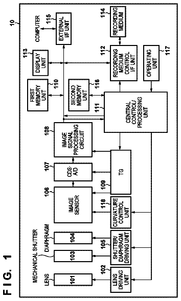
FIG. 3 is a block diagram of the configuration of an imaging device of the embodiment.
FIG. 4 is an explanatory diagram of an overview of candidate image extraction and main subject determination of the embodiment.
FIG. 5 is an explanatory diagram of a distance between a candidate image frame and a determination reference point of the embodiment.
FIG. 6 is a flowchart of a camerawork determination process and a main subject determination process of a first process example.
FIG. 7 is a flowchart and an explanatory diagram of a camerawork determination process of the first process example.
FIG. 8 is a flowchart of a main subject determination process applicable to each process example of the embodiment.
FIG. 9 is an explanatory diagram of a camerawork determination process of a second process example.
FIG. 10 is a flowchart of the camerawork determination process of the second process example.
FIG. 11 is a flowchart and an explanatory diagram of a camerawork determination process of a third process example.
FIG. 12 is an explanatory diagram of a camerawork determination process of a fourth process example.
FIG. 13 is a flowchart of the camerawork determination process of the fourth process example.
FIG. 14 is an explanatory diagram of a camerawork determination process of a fifth process example.
FIG. 15 is a flowchart of the camerawork determination process of the fifth process example.
FIG. 16 is a flowchart of an interim zoom determination process of the fifth process example.
FIG. 17 is an explanatory diagram of a camerawork determination process of a sixth process example.
FIG. 18 is a flowchart of the camerawork determination process of the sixth process example.
FIG. 19 is a flowchart of a post-zoom determination process of the sixth process example.
FIG. 20 is an explanatory diagram of a camerawork determination process of a seventh process example.
FIG. 21 is a flowchart of the camerawork determination process of the seventh process example.
FIG. 22 is a flowchart of an interim pan determination process of the seventh process example.
FIG. 23 is an explanatory diagram of a camerawork determination process of an eighth process example.
FIG. 24 is a flowchart of the camerawork determination process of the eighth process example.
FIG. 25 is a flowchart illustrating a post-pan determination process of the eighth process example.
FIG. 26 is a block diagram of the configuration of another imaging device of the embodiment.
FIG. 27 is an explanatory diagram of overviews of candidate image extraction and focusing degree determination of a ninth process example.
FIG. 28 is an explanatory diagram of the focusing degree determination of the ninth process example.
FIG. 29 is an explanatory diagram of a camerawork determination process of the ninth process example.
FIG. 30 is a flowchart of the camerawork determination process of the ninth process example.
FIG. 31 is a flowchart of a main subject determination process applicable to the ninth process example of the embodiment.
FIG. 32 is an explanatory diagram of main subject determination of the ninth process example.
FIG. 33 is a block diagram when an embodiment is applied to a computer device.
Description of embodiments
Hereinafter, embodiments will be described in the following order.
<1. Configuration of image processing device of embodiment>
<2. Configuration of imaging device of embodiment>
<3. Opportunity and objective of main subject determination, etc.>
<4. First process example (pan operation determination>
<5. Second process example (post-pan determination)>
<6. Third process example (zoom operation determination)>
<7. Fourth process example (post-zoom determination)>
<8. Fifth process example (post-pan zoom operation determination)>
<9. Sixth process example (post-pan post-zoom determination)>
<10. Seventh process example (post-zoom pan operation determination)>
<11. Eighth process example (post-zoom post pan determination)>
<12. Ninth process example (focusing determination)>
<13. Application to program and computer device>
<14. Modification examples>
<1. Configuration of Image Processing Device of Embodiment>
FIG. 1 illustrates a configuration example of an image processing device according to the embodiment.
An image processing device 1 includes a main subject determination unit 2 and a camerawork determination unit 3 .
The camerawork determination unit 3 determines camerawork at the time of imaging and sets a determination start timing of a main subject in image data based on the determination. The camerawork determination unit 3 inputs detection information Id regarding camerawork at the time of imaging and determines the camerawork based on the detection information Id. Then, according to the determination result, the main subject determination unit 2 is notified of a timing of the start of main subject determination.
The camerawork may be operations or manipulations of the user or photographer capturing a subject in a captured image or operations or manipulations of searching for an intended composition or a focus state. Specifically, the camerawork is, for example, panning, tilting, zooming, and manual focus. Accordingly, the detection information Id is detection information regarding a manipulation such as zoom or manual focus performed by a photographer or detection information of a sensor detecting a motion of an imaging device, such as an angular velocity sensor (gyro sensor) or an acceleration sensor.
Further, “camerawork at the time of imaging” refers to camerawork at the present time or camerawork from when image data was captured previously. For example, the camerawork at the time of imaging refers to camerawork performed at the present time by a photographer when the image processing device 1 is a device included in an imaging apparatus 10 to be described below or is a device which is connected to an imaging apparatus and is supplied with captured image data in real time. Further, the camerawork at the time of imaging refers to camerawork from previous imaging when main subject determination is performed on previously captured image data.
The main subject determination unit 2 performs a main subject determination process on input image data Dg based on the determination start timing set by the camerawork determination unit 3 . For example, the main subject determination unit 2 observes a position state of a subject in image data of a plurality of frames from the determination start timing of a main subject and determines the main subject among subjects conforming to a specific position condition. For example, the main subject determination unit 2 observes a focus state of a subject in image data of at least one frame from the determination start timing and determines a main subject among subjects conforming to a specific focus condition. The main subject determination unit 2 sets one subject or a plurality of subjects as the main subject through such processes.
Then, the main subject determination unit 2 outputs main subject information Dm as the determination result.
The image processing device 1 including the main subject determination unit 2 and the camerawork determination unit 3 described above can be realized by a central processing unit (CPU) or a digital signal processor (DSP) which is an arithmetic processing device.
Realizing the function of the main subject determination unit 2 by a CPU or the like and the function of the camerawork determination unit 3 by an image processing DSP or the like connected to the CPU or as a cooperation process can also be considered.
The flow of a process for the main subject determination performed by the image processing device 1 is illustrated in FIG. 2 .
In Step F 1 , the camerawork determination unit 3 determines camerawork performed by a photographer. Then, when a predetermined camerawork situation is detected in Step F 2 , the camerawork determination unit 3 sets the determination start timing in Step F 3 . For example, a determination execution flag is set to be turned on.
Accordingly, the main subject determination unit 2 performs the main subject determination process in Step F 4 and determines that a subject conforming to a predetermined condition is a main subject.
In Step F 5 , the main subject determination unit 2 outputs the main subject information Dm which is a main subject determination result to transmit and receive the main subject information Dm to and from an application program or the like.
The application program or the like performs a process according to the fact that a main subject image is specified. For example, focus control, a tracking process, or an image effect process is performed.
The processes of Steps F 1 to F 3 performed by the camerawork determination unit 3 are considered to be diverse. Specific examples are described below as process examples of the imaging apparatus 10 , in which the following situations are determined and the determination start timing is set:
1. Pan operation determination: it is determined that a pan operation starts, and then the determination start timing is set so that the main subject determination process is performed during the pan operation;
2. Post-pan determination: it is determined that a pan operation is performed and ends, and then the determination start timing is set so that the main subject determination process is performed after the end of the pan operation;
3. Zoom operation determination: it is determined that a zoom operation starts, and then the determination start timing is set so that the main subject determination process is performed during the zoom operation;
4. Post-zoom determination: it is determined that a zoom operation is performed and ends, and then the determination start timing is set so that the main subject determination process is performed after the end of the zoom operation;
5. Post-pan zoom operation determination: it is determined that a pan operation is performed and ends and a zoom operation subsequently starts, and then the determination start timing is set so that the main subject determination process is performed during the zoom;
6. Post-pan post-zoom determination: it is determined that a pan operation is performed and ends and a zoom operation is subsequently performed and ends, and then the determination start timing is set so that the main subject determination process is performed after the end of the zoom;
7. Post-zoom pan operation determination: it is determined that a zoom operation is performed and ends and a pan operation starts, and then the determination start timing is set so that the main subject determination process is performed during the pan;
8. Post-zoom post-pan determination: it is determined that a zoom operation is performed and ends and a pan operation is subsequently performed and ends, and then the determination start timing is set so that the main subject determination process is performed after the pan; and
9. Post-manual-focus determination: it is determined that a manual focus operation is performed and ends, and then the determination start timing is set so that the main subject determination process is performed after the end of the manual focus operation.
The details of the above-described processes will be described as first to ninth process examples of the imaging apparatus 10 .
The image processing device 1 in FIG. 1 can estimate a subject intended as a target by a photographer through camerawork and automatically perform the main subject determination by performing the camerawork determination and the main subject determination as in the example of FIG. 2 described above. Accordingly, the main subject determination can be performed without dependency on a manual manipulation of a user, and thus operability of the user is considerably improved by mounting the image processing device 1 in FIG. 1 on various electronic apparatuses performing an operation according to main subject setting.
<2. Configuration of an Imaging Device>
Hereinafter, the main subject determination operation will be described in detail exemplifying the imaging apparatus 10 including the above-described image processing device.
A configuration example of the imaging apparatus 10 according to the embodiment is illustrated in FIG. 3 . This configuration example is appropriate for first to eighth process examples to be described below. A configuration example of the imaging apparatus 10 in the case of the ninth process example will be described below.
The imaging apparatus 10 is considered to be a so-called digital still camera or a digital video camera and is an apparatus that performs capturing and recording of a still image or a moving image and includes the imaging processing device described in the claims.
The imaging apparatus 10 shown in FIG. 3 has an optical system 11 , an imager 12 , an optical system drive unit 13 , a sensor unit 14 , a recording unit 15 , a communication unit 16 , a digital signal processing unit 20 , a control unit 30 , a user interface controller (hereinafter, “UI controller”) 32 , and a user interface 33 .
The optical system 11 has lenses such as a cover lens, a zoom lens, and a focus lens and a throttle mechanism. By this optical system 11 , light from a subject is collected in the imager 12 .
The imager 12 , for example, has a CCD (Charge Coupled Device) type or CMOS (Complementary Metal OxideSemiconductor) type image sensor.
The imager 12 , for example, performs a CDS (Correlated Double Sampling) process, an AGC (Automatic Gain Control) process and the like for an electrical signal obtained through photoelectric conversion in the image sensor, and further performs an A-D (Analog-Digital) conversion process. Then, the imager 12 outputs an imaging signal as digital data to the digital signal processing unit 20 of a rear stage.
The optical system drive unit 13 drives the focus lens in the optical system 11 under the control of the control unit 30 to perform a focus operation. Thus, for example, an autofocus operation is performed.
For the focus lens, lens movement is also possible through manual focus according to a user's manipulation. The user can arbitrarily set a focus position by manipulating a focus lens transport mechanism formed in a lens barrel.
The optical system drive unit 13 drives the throttle mechanism of the optical system 11 under the control of the control unit 30 to perform exposure adjustment.
The optical system drive unit 13 drives the zoom lens of the optical system 11 under the control of the control unit 30 to perform a zoom operation. The user can give an instruction for a zoom operation by manipulating a zoom lever of the manipulation unit 35 to be described below. Thus, the user can obtain any angle-of-view state.
The digital signal processing unit 20 , for example, is configured as an image processor by a DSP and the like. The digital signal processing unit 20 performs various types of signal processes for a digital signal (captured image signal) from the imager 12 .
For example, the digital signal processing unit 20 includes a pre-processing unit 21 , a synchronization unit 22 , a YC generation unit 23 , a resolution conversion unit 24 , a codec unit 25 , and a candidate detection unit 27 .
The pre-processing unit 21 performs a clamping process of clamping a black level of R, G, and B to a predetermined level, or a correction process among color channels of R, G, and B with respect to the captured image signal from the imager 12 .
The synchronization unit 22 performs a demosaicing process such that image data for each pixel has color components of all of R, G, and B.
The YC generation unit 23 generates (separates) a luminance (Y) signal and a color (C) signal from the image data of R, G, and B.
The resolution conversion unit 24 executes a resolution conversion process on the image data on which various types of signal processes have been performed.
The codec unit 25 , for example, performs a coding process for recording or communication with respect to the image data for which the resolution conversion has been performed.
The candidate detection unit 27 performs an image analysis process in units of frames (or per intermittent frame) for a captured image signal (luminance signal and color signal) obtained by, for example, the YC generation unit 23 , and then extracts a candidate image. In other words, face image detection, human body detection, and the like are performed for image data continuously input on a time axis, and then images serving as candidates for a main subject are extracted.
Note that face detection, human body detection, and the like can be performed using techniques of pattern matching and the like in image analysis performed with respect to captured image data, but if only a dictionary used in pattern matching is replaced, other detectors can also be realized in principle. For example, extraction of candidate images of a main subject for dog detection (of a certain breed), cat detection, and the like is possible.
In addition, for example, detecting a moving body and setting the moving body to be a candidate image using a technique of moving body detection based on a frame difference can also be considered, and a technique of extracting an area of interest that is called saliency (Saliency) may be used. Various techniques of extracting and selecting candidate images are considered.
The candidate detection unit 27 , for example, a face image is detected, and an area in which the face image is present is extracted as a candidate image frame.
With regard to the extracted candidate image, position information of the candidate image frame (x and y coordinate values on a screen, information of a subject distance, and the like) or size information (for example, the width, height, and number of pixels of the candidate image frame, and the like) are transferred to the control unit 30 as candidate image information. Note that, here, since the candidate image information is information indicating a frame of an image area serving as a candidate image, the term of candidate image information is also referred to as “candidate image frame information.”
In addition, the candidate detection unit 27 may perform a smoothing process, an outlier (outlier) removal process, or the like for the image to generate candidate image frame information.
A functional configuration in which the candidate detection unit 27 is implemented in the digital signal processing unit 20 is set in the example of FIG. 3 , but this is an example, and the control unit 30 may execute the process of the candidate detection unit 27 .
The control unit 30 is configured by a micro-computer (arithmetic processing device) that has a CPU, a ROM (Read Only Memory), a RAM (Random Access Memory), a flash memory, and the like.
By executing a program stored in the ROM, the flash memory, and the like, the CPU comprehensively controls the entire imaging apparatus 10 .
The RAM serving as a work area when the CPU performs various kinds of data processes is used for temporarily storing data, programs, and the like.
The ROM and the flash memory (non-volatile memory) are used for storing an OS (Operating System) necessary for control of each unit by the CPU, content files such as image files, application programs for various operations, firmware, and the like. For example, programs for executing the main subject determination process that will be described later in the present example, and further application programs that use main subject determination results, and the like are stored therein.
The control unit 30 described above controls operations of necessary units relating to instruction of various signal processes in the digital signal processing unit 20 , imaging operations and recording operations according to a user manipulation, a reproducing operation of recorded image files, camera operations such as zooming, focusing, and exposure adjustment, user interface operations, and the like.
In the case of the present embodiment, the control unit 30 has the functions of the main subject determination unit 30 a and the camerawork determination unit 30 b and performs a camerawork determination process and a main subject determination process to be described below.
In the case of the configuration in FIG. 3 , the camerawork determination unit 30 b performs any one of the pan operation determination, the post-pan determination, the zoom operation determination, the post-zoom determination, the post-pan zoom operation determination, the post-pan post-zoom determination, the post-zoom pan operation determination, and the post-zoom post-pan determination described above. Then, the start timing of the main subject determination process is set. Specifically, a determination execution flag (a determination execution flag FDon to be described below) is turned on.
The main subject determination unit 30 a performs a process of determining a main subject in a candidate image according to the setting of the start timing which is based on the determination result of the camerawork determination unit 30 b.
The user interface 33 executes display output and audio output to a user, and receives input of a user manipulation. For this reason, the user interface has a display device, a manipulation device, a speaker device, a microphone device, and the like. Herein, a display unit 34 and a manipulation unit 35 are shown.
The display unit 34 is a display unit that performs various types of display for a user (a photographer and the like), and for example, is formed using a display device, such as an LCD (Liquid Crystal Display) or an organic EL (Electro-Luminescence) display, which is formed on a housing of the imaging apparatus 10 . In addition, the display unit may be formed using the LCD or the organic EL display in a so-called view finder form.
This display unit 34 includes the display device and a display driver that allows the display device to perform display. The display driver allows various types of display to be performed on the display device based on the instruction of the control unit 30 . For example, the display driver reproduces and displays a still image or a dynamic image captured and recorded in a recording medium, or displays a through image (subject monitoring image) as a dynamic image based on captured image data of each frame, which is captured during release (a shutter manipulation) standby, on a screen of the display device. Furthermore, the display driver allows various manipulation menus, icons, messages and the like, that is, a GUI (Graphical User Interface), to be displayed on the screen. In the case of the present embodiment, for example, display that helps the user to ascertain a determination result obtained from main subject determination on the through image or reproduced image is also performed.
The manipulation unit 35 has an input function of receiving a user manipulation, and sends a signal corresponding to the input manipulation to the control unit 30 .
The manipulation unit 35 , for example, is realized by various manipulators provided on the housing of the imaging apparatus 10 , a touch panel formed on the display unit 34 , and the like.
As the manipulator on the housing, a reproduction menu start button, a decision button, an arrow key, a cancellation button, a zoom lever, a slide key, a shutter button (a release button) and the like are provided.
Furthermore, by a touch panel manipulation using the icons and menus displayed on the touch panel and the display unit 34 , various kinds of manipulation may be possible.
An operation of the display unit 34 of the user interface 33 and the like is controlled by the UI controller 32 according to instructions of the control unit 30 . In addition, information of manipulations by the manipulation unit 35 is transmitted to the control unit 30 by the UI controller 32 .
In the case of the present embodiment, for example, a manipulation of a zoom lever (a wide key or a tele key) is used for the camerawork determination. The control unit 30 detects a manipulation of the zoom lever via the UI controller 32 and controls the optical system drive unit 13 according to information regarding the manipulation to perform the zoom lens drive.
The recording unit 15 includes, for example, a non-volatile memory, and serves as a storage area for storing image files (content files) such as still image data or dynamic image data, attribute information of the image files, thumbnail images and the like.
The image files are stored in the form of, for example, a JPEG (Joint Photographic Experts Group), a TIFF (Tagged Image File Format), a GIF (Graphics Interchange Format) and the like.
The actual form of the recording unit 15 can be variously considered. For example, the recording unit 15 may be a flash memory that is embedded in the imaging apparatus 10 , or may have a form based on a memory card (for example, a portable flash memory) attachable to and detachable from the imaging apparatus 10 and a card recording and reproduction unit that performs recording and reproduction access to the memory card. Furthermore, the recording unit may be realized in the form of an HDD (Hard Disk Drive) and the like that is embedded in the imaging apparatus 10 .
Furthermore, in the present example, a program for performing the camerawork determination process and the main subject determination process that will be described later may be stored in the recording unit 15 .
The communication unit 16 performs data communication or network communication with an external device in a wired or wireless manner.
For example, the communication unit performs communication of the captured image data (still image files or dynamic image files) with an external display apparatus, a recording apparatus, a reproduction apparatus and the like.
Furthermore, as a network communication unit, the communication unit may perform communication through various networks, for example, the Internet, a home network, or a LAN (Local Area Network), or perform various types of data transmission and reception with a server, a terminal and the like on the network.
The sensor unit 14 comprehensively indicates various sensors. Any of the various sensors of the sensor unit 14 delivers each of the detected information to the control unit 30 . The control unit 30 can perform various kinds of control using the information detected by the sensor unit 14 .
For example, a gyro sensor (angular velocity sensor) or an acceleration sensor detecting all of the motions of the imaging apparatus 10 , such as camera shaking or a posture or a movement (a pan movement, a tilt movement, or the like) of the imaging apparatus 10 is provided as the sensor unit 14 . For example, the control unit 30 can detect panning or tilting of the imaging apparatus 10 based on a signal detected by the gyro sensor.
A zoom lens position sensor detecting the position of a zoom lens and a focus lens position sensor detecting the position of a focus lens in the optical system 11 is provided as the sensor unit 14 . Alternatively, a sensor detecting a manual manipulation (manipulation of a lens barrel ring) of a focus lens is provided in some cases. The control unit 30 can detect a manual focus manipulation of the user based on information detected by the focus lens position sensor or information of the sensor detecting the manual manipulation of the focus lens.
A sensor detecting an opening amount of a mechanical iris (throttle mechanism) is provided as the sensor unit 14 in some cases.
An illuminance sensor detecting outside illuminance through exposure adjustment or the like or a ranging sensor measuring a subject distance may be provided as the sensor unit 14 .
In the imaging apparatus 10 , the configuration portion of the image processing device 1 described in FIG. 1 is as follows.
A configuration corresponding to the main subject determination unit 2 of the image processing device 1 in FIG. 1 is mounted as the main subject determination unit 30 a on the control unit 30 of the imaging apparatus 10 by software. A configuration corresponding to the camerawork determination unit 3 is mounted as the camerawork determination unit 30 b on the control unit 30 by software.
The control unit 30 controls execution of an operation which is an image processing method described in the claims by performing a process based on a program described in the claims.
<3. Opportunity and Objective of Main Subject Determination, Etc.>
In the present embodiment, main subject determination is performed as described in the first to the ninth process examples to be described later, and an opportunity, objective, etc. for performing main subject determination in the imaging apparatus 10 will be described.
First, an example of using a main subject determination result will be described.
Main subject determination is executed when, for example, a user (photographer) aims at a shutter timing (release timing), but the control unit 30 can perform the following process after a main subject is automatically determined.
Tracking Process
A main subject set in each captured frame is tracked. For example, a main subject is specified on a through image display for the user, and provided for adjusting an angle of view performed by the user (for example, for decision of a subject in a state in which a camera is held in a hand).
Note that, as presentation of a main subject, highlight display of the frame of the main subject on the through image display by the display unit 34 is considered. In addition, the highlight display or the like may be performed for a given period immediately after the determination, or may be performed as long as the main subject is present within the through image.
Focusing
Auto focus is controlled for a main subject. In addition, in accordance with the tracking process, focus is adjusted tracking the main subject even when the main subject moves around.
Exposure Adjustment
Automatic exposure adjustment is performed based on brightness (luminance) of a main subject.
Directivity Adjustment
When sound collection is performed using a microphone together with capturing (for example, dynamic image capturing), directivity adjustment is performed according to a direction of a main subject within a field of view.
Zoom Control
The description continues in the full USPTO document.
 Lapsed, fee not paid6 drawings