 Lapsed, fee not paid7 drawings
Consumer Products · US 9,939,783 B2
Water resistant vent in an electronic device
An electronic device includes a compound designed to raise a surface tension of a water-based solution.
US 9,939,787 B2 · Assignee: Samsung Electronics Co., Ltd. · Inventors: Baek; Sang-In et al.
Sheet 1 of 45 from the published document. All sheets in the USPTO PDF
A wearable electronic device and method of use are disclosed, including a main body, and at least one strap fixed to the main body. The strap includes a core member mounted with at least one electronic component, an electric connector disposed on the core member, and a band member enclosing at least one part of the core member disposed with the electric connector, wherein the at least one electronic component is electrically coupled to the main body through the electric connector.
Electronic devices perform an increasing number functions while continually being miniaturized, becoming thus both highly portable and very useful. Such electronic devices are generally carried in a pocket of a user, but may also be installed in a wearable device, attachable, for example, to a wrist, head or arm. Devices wearable on a human body may generally include a main body for executing a function, and a strap affixing the main body to the human body or any other suitable structures. Wearable devices may be used as standalone as subordinate devices, or may be tethered or otherwise subordinate to other electronic devices. When wearable electronic devices are used as subordinate electronic devices, a communication method using a local area network module may be implemented. Due to using wearable electronic devices, it the convenience of other non-wearable electronic devices is reduce
1 of 45 drawing sheets so far from the published document, cropped to the drawing. Every sheet is in the USPTO PDF.
What the patent claimed, word for word. All of it is now free to use.
This application claims priority under 35 U.S.C. § 119 to an application filed in the Korean Intellectual Property Office on Sep. 2, 2013 and assigned Serial No. 10-2013-0105144, the contents of which are incorporated herein by reference.
Various embodiments of the present disclosure relates to a wearable electronic device.
Electronic devices perform an increasing number functions while continually being miniaturized, becoming thus both highly portable and very useful. Such electronic devices are generally carried in a pocket of a user, but may also be installed in a wearable device, attachable, for example, to a wrist, head or arm.
Devices wearable on a human body may generally include a main body for executing a function, and a strap affixing the main body to the human body or any other suitable structures. Wearable devices may be used as standalone as subordinate devices, or may be tethered or otherwise subordinate to other electronic devices. When wearable electronic devices are used as subordinate electronic devices, a communication method using a local area network module may be implemented. Due to using wearable electronic devices, it the convenience of other non-wearable electronic devices is reduced. Accordingly, the use of wearable electronic devices is now expanding gradually.
Various embodiments of the present disclosure provide a strap and a wearable electronic device including the wearable member.
Various embodiments of the present disclosure also provide a wearable electronic device providing reliability although being used for a long time.
Various embodiments of the present disclosure also provide a wearable electronic device configured to utilize a strong coupling structure between a main body and a strap.
Various embodiments of the present disclosure also provide a wearable electronic device capable of strongly coupling electronic components to other structures with a strap.
Various embodiments of the present disclosure also provide a wearable electronic device capable of strongly affixing an electric connector to a strap and simultaneously facilitate mobility.
Various embodiments of the present disclosure also provide a substrate unit configured to electrically couple at least two substrates to one another and a wearable electronic device including the substrate unit.
The various embodiments may provide a wearable electronic device, in which a connector electrically coupling at least two substrates provided in the electronic device are configured to accommodate repeated forward bending, thereby reducing required installation space and allowing more miniaturization of the electronic device.
The wearable electronic device may contain a relatively larger number of signal lines when electrically coupling at least two substrates.
The various embodiments may provide a buckle and a wearable electronic device including the buckle.
The wearable electronic device may partially dispose at least one electronic component on a buckle.
The various embodiments provide an electronic watch including a main body including a display, at least one strap coupled to at least a part of the main body, and a camera module mounted on a part of the at least one strap.
In one aspect of this disclosure, an electronic watch is disclosed, including a main body comprising a display, at least one strap coupled to at least one part of the main body; and at least one camera module mounted on a part of the at least one strap.
In another aspect of this disclosure, a wearable electronic device is disclosed, including a main body comprising a processor, a wearable member coupled to at least one part of the body, and at least one electronic component mounted on a part of the wearable member.
In another aspect of this disclosure, a method of operating an electronic watch is disclosed, the electronic watch including a main body including a display, at least one strap coupled to at least one part of the main body, and at least one camera module mounted on a part of the at least one strap, the method comprising: receiving an image taking command at the main body, transmitting an image obtaining command from the main body to the camera module based on the image taking command, obtaining an image by the camera module, and transmitting the obtained image to the main body.
In another aspect of this disclosure, a method of operating an electronic watch, the electronic watch including a buckle coupled to at least one part of the at least one strap, wherein the buckle includes a speaker electrically coupled with a main body, the method comprising: receiving a sound playback command at the main body, processing sound data to be played back, at the main body, transmitting the processed sound data to the speaker; and replaying a sound by the speaker.
In another aspect of this disclosure, a wearable electronic device is disclosed, including a main body, and at least one strap fixed to the main body, wherein the strap includes: a core member mounted with at least one electronic component, an electric connector disposed on the core member, a band member enclosing at least one part of the core member disposed with the electric connector, wherein the at least one electronic component is electrically coupled to the main body through the electric connector.
In another aspect of this disclosure, a wearable electronic device is disclosed, including a main body, and at least one strap fixed to the main body, wherein the strap includes: a core member, a flexible printed circuit penetrating one surface of the core member and another surface opposite to the one surface and fixed to the both surfaces, a sealing member installed to seal a part of the core member penetrated by the flexible printed circuit, a band member formed using a double injection process to enclose at least one part of the core member disposed with the flexible printed circuit and the sealing member and formed of softer material than the core member, at least one electronic component installed to be electrically coupled to the flexible printed circuit exposed to at least one part of the band member, and a cover mounted to seal an exposed part of the band member mounted with the electronic component.
In another aspect of this disclosure, a wearable electronic device is disclosed, including: a main body, at least one strap fixed to the main body, and a buckle installed on an end of the strap to be fastened to another strap and mounted with at least one electronic component, wherein the buckle comprises: a housing fixed to the end of the strap and mounted with the at least one electronic component, and a fastening unit disposed on an outer surface of the housing and fastened to the another strap.
In another aspect of this disclosure, a wearable electronic device is disclosed, including: a main body, at least one strap fixed to the main body, a housing installed on an end of the strap and having a unit containing space therein, at least one electronic component contained in the unit containing space of the housing, a cover for sealing the unit containing space, at least one sealing member disposed between the cover and the unit containing space for sealing the unit containing space, and at least one band fixing pole protruding from an outer surface of the cover and correspondingly inserted into at least one opening formed on another strap.
In another aspect of this disclosure, a wearable electronic device is disclosed, including: a main body, at least one strap fixed to the main body, and a buckle fixed to an end of the strap to be fastened to another strap and mounted with at least one electronic component, wherein the strap comprises: a core member mounted with at least one electronic component, an electric connector disposed on the core member, a band member coupled with the core member to enclose at least one part of the core member disposed with the electric connector, wherein the at least one electronic component is electrically coupled to the main body through the electric connector, and wherein the buckle comprises: a housing fixed to the end of the strap and mounted with the at least one electronic component, and a fastening unit disposed on an outer surface of the housing and fastened to the another strap.
The present disclosure will become more apparent from the following detailed description when taken in conjunction with the accompanying drawings in which:
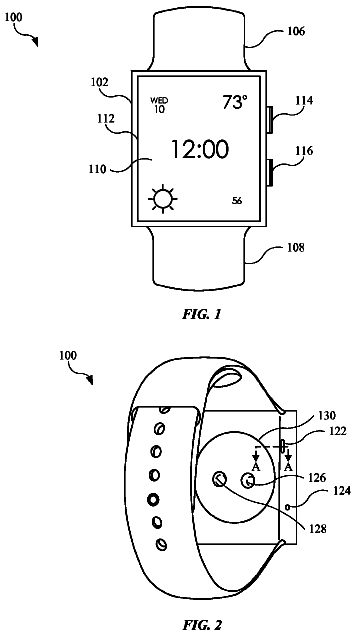
FIG. 1 is a perspective view of an example wearable electronic device according to embodiments of the present disclosure;
FIG. 2 is a separate perspective view of an example wearable electronic device;
FIG. 3A and FIG. 3B are a top view and a rear view of an example core member according to embodiments of the present disclosure;
FIG. 4A and FIG. 4B are a top view and a rear view of an example core member attached with a flexible printed circuit (FPC) according to embodiments of the present disclosure;
FIG. 5A and FIG. 5B are a separate perspective view and a combination view illustrating an example state in which a sealing member is installed in the core member according to embodiments of the present disclosure;
FIG. 6A and FIG. 6B are a top view and a rear view of an example band member injected after applying the FPC and the sealing member to the core member according to embodiments of the present disclosure;
FIG. 7 is a cross-sectional view of an example strap according to embodiments of the present disclosure;
FIG. 8A , FIG. 8B and FIG. 8C are diagrams illustrating an example combination structure between the strap and the main body of the wearable electronic device according to embodiments of the present disclosure;
FIG. 9 is a diagram illustrating an example angle at which the strap is fixed to the main body according to embodiments of the present disclosure;
FIG. 10A and FIG. 10B are diagrams illustrating an example configuration of the core member according to embodiments of the present disclosure;
FIG. 11A and FIG. 11B are diagrams illustrating an example configuration of the core member and the band member for improving wearability according to embodiments of the present disclosure;
FIG. 12A , FIG. 12B and FIG. 12C are diagrams illustrating an example configuration, in which an electric connector is applied to the core member according to embodiments of the present disclosure;
FIG. 13 is a separate perspective view illustrating an example state, in which a substrate is installed in the main body of the wearable electronic device according to embodiments of the present disclosure;
FIG. 14 is a configuration view of an example substrate applied to the wearable electronic device according to embodiments of the present disclosure;
FIG. 15 is a cross-mid sectional view illustrating an example state, in which the substrate is applied to the wearable electronic device according to embodiments of the present disclosure;
FIG. 16 is a configuration view illustrating an example state, in which the substrate applied to the wearable electronic device is folded according to embodiments of the present disclosure;
FIG. 17 is a mid-sectional configuration view of an example signal line of the substrate applied to the main body of the wearable electronic device according to embodiments of the present disclosure;
FIG. 18 is a configuration diagram of an example substrate unit, illustrating an example state, in which two substrates are electrically coupled to each other by a connector according to embodiments of the present disclosure;
FIG. 19 is a cross-mid sectional view illustrating an example state, in which the two substrates are applied to the main body of the wearable electronic device according to embodiments of the present disclosure;
FIG. 20 is a cross-mid sectional view illustrating an example state, in which a pogo connector is installed in the main body of the wearable electronic device according to embodiments of the present disclosure;
FIG. 21A and FIG. 21B are diagrams illustrating an example combination between a housing of a buckle and the strap according to embodiments of the present disclosure;
FIG. 22A and FIG. 22B are diagrams illustrating an example combination between the housing and a cover of the buckle according to embodiments of the present disclosure;
FIG. 23 is a separate perspective view of an example locking unit disposed in the buckle according to embodiments of the present disclosure;
FIG. 24A and FIG. 24B are diagrams illustrating an example operation of a buckle link of the buckle according to embodiments of the present disclosure;
FIG. 25A and FIG. 25B are diagrams illustrating an example operation of a buckle link of the buckle according to embodiments of the present disclosure;
FIG. 26 is a diagram of an example strap without a cover for locking electronic components according to embodiments of the present disclosure; and
FIG. 27A , FIG. 27B , FIG. 27C , FIG. 27D and FIG. 27E are configuration views illustrating example states, in which electronic components are applied to straps of the wearable electronic device according to embodiments of the present disclosure.
Hereinafter, various embodiments of the present disclosure will be described in detail with reference to the attached drawings. While describing the present disclosure, when it is determined that a detailed description of well-known typical functions or configurations may make the points of the present disclosure unclear, the detailed description will be omitted. Also, terms described below are defined considering functions thereof in the embodiments, which may vary with a user, an intention of an operator, or a preferred practice. Accordingly, definitions thereof when given, are given with reference to the content of the entire specification.
In describing the various embodiments of the present disclosure, a wearable electronic device may include a main body and at least one strap combined with the main body.
In describing various embodiments of the present disclosure, the wearable electronic device may be applied to various devices, mounted on a human body or mounted on a suitable structure via the strap. According to various embodiments, the wearable electronic device may be affixed to various portions of a human body such as a wrist, an arm, a head part, etc. However, the wearable electronic device is not limited thereto, but may also be affixed to various devices and structure by the strap.
Electronic devices may include various wearable electronic devices that are independently utilizable, or utilizable when coupled to other electronic devices. In one embodiment, the wearable electronic device may be coupled to another electronic device, communicating therewith using a communication module. In this case, the wearable electronic device may output information to another electronic device, receive and vicariously output information outputted by still another electronic device, and may output information together with yet another electronic device. All these processes may be performed simultaneously. According to one embodiment, the information may be visually outputted through a display unit, acoustically outputted through a speaker, or tactually outputted through vibrations. According to one embodiment, the communication module may be a local area network (LAN) module. According to one embodiment, the LAN module may be at least one of a WiFi communication module, a Bluetooth communication module, an infrared communication module, or a near field communications (NFC) module.
Various embodiments of the present disclosure are described in relation to a wearable electronic device, but may also be applied to various general devices, to which the strap is applicable, in addition to electronic devices.
Various embodiments of the present disclosure may provide at least two substrates mutually folded by a connector. According to the embodiment, a configuration described above may be applied to the main body of the wearable electronic device. However, it is not limited thereto, and may be applied to various electronic devices, to which at least two substrates are separately applied, such as personal digital assistants (PDA), a laptop computer, a mobile phone, a smart phone, a netbook, a mobile Internet device (MID), an ultra mobile personal computer (PC, UMPC), a tablet PC, a navigation, an MP3, an electronic watch, etc.
In describing various embodiments of the present disclosure, the wearable electronic device may be applied to various devices including a main body, at least one strap combined with the main body, and a buckle provided on an end of the at least one strap.
Various embodiments of the present disclosure are described in relation to a wearable electronic device but may be applied to various general devices including the strap and the buckle applied to an end of the strap, according to the embodiment, in addition to electronic devices.
Various embodiments of the present disclosure, according to description, may be described as a wearable member, a strap, and a connection body. The terms mean the same component having a structure fixing the main body to an external object and containing at least one electronic component, and may be mutually interchangeable.
Hereinafter, various embodiments of the present disclosure will be described.
FIG. 1 is a perspective view of a wearable electronic device 1 according to embodiments of the present disclosure. According to the various embodiments, a watch-type electronic device wearable on a wrist of a human body will be described.
The wearable electronic device 1 may include a main body 2 and straps 10 and 10 ′ fixed to both ends of the main body, respectively. The strap in some embodiments may be formed as one piece, being coupled from one end of the main body 2 to the other end without break or separation. Similarly, the strap, when as a plurality of sections, may form two or more separate strap ends, such as the straps 10 and 10 ′. In FIG. 1 , for convenience of description, a pair of straps 10 and 10 ′ are illustrated as an example.
The main body 2 may be equipped with a display unit 3 , and at least one of the straps 10 or 10 ′ may be equipped with electronic components to enable execution of functions of the wearable electronic device 1 . In one embodiment, the display unit 3 may be equipped with a touch screen unit capable of inputting and outputting data. The electronic components may also include at least one of a camera 5 or a speaker 6 . The camera 5 , for example, may be installed on, for example, a middle part of the strap, separate from the main body 2 and distanced at a certain interval. The speaker 6 may be installed on an end of the strap. Although not shown in the drawings, various other devices, such as a microphone, an antenna, and a sensor for sensing an environmental condition or a state of a human body and may be included in the wearable electronic device 1 .
In one embodiment, a buckle 4 may be installed on an end of the strap 10 . For example, when allowing the main body 2 to be put on a wrist, the pair of straps 10 and 10 ′ are turned inwards, following the contour of the wrist. As such, when the ends of the straps 10 and 10 ′ meet, the buckle 4 of the strap 10 is fastened to the strap 10 ′, thereby affixing the wearable electronic device 1 to the wrist. In one embodiment, the wearable electronic device 1 may connect the two straps 10 and 10 ′ to each other by fastening the buckle 4 installed on the strap 10 to at least one of a plurality of openings formed on the strap 10 ′.
According to the various embodiments, the pair of straps 10 and 10 ′ are fixed to both ends of the main body 2 to be opposite to each other. However, the straps 10 and 10 ′ are not limited to this variation. For example, one strap may be installed on one side of the main body 2 with a length sufficient to fully enclose the wrist and then affix itself to the other end of the main body 2 .
According to the various embodiments, the straps 10 and 10 ′ may be formed using multiple materials each having different degrees of softness. In one embodiment, the straps 10 and 10 ′ are manufactured using a first material having a first softness as a core member ( 11 of FIG. 2 ) and a second material having second softness as a band member ( 13 of FIG. 2 ), the second material at least partially enclosing the core member 11 . In one embodiment, the first softness may be smaller than the second softness. Hereinafter, the core member 11 may be referred as a first member and the band member 13 may be referred as a second member.
According to the various embodiments, since the band member 13 has a relatively high degree of softness, it has its own elasticity and is capable of being formed into the external shape of the straps 10 and 10 ,′ thereby providing a user with excellent wearability. It also allows the wearable electronic device 1 to be affixed to various devices via an available bending range. At least one of urethane, silicone, rubber, thermoplastic polyurethane (TPU), or thermoplastic silicone vulcanizate (TPSiV) may be used a material for the band member 13 .
According to the various embodiments, a member having relatively lesser degree of softness may be to form the core member 11 , which may be formed of a more rigid material. In one embodiment, the straps 10 and 10 ′ are manufactured such that the band member 13 partially encloses the core member 11 , and may be further configured to expose parts to which the electronic components may be attached. In one embodiment, since the electronic components are mounted on the exposed parts of the core member 11 , and the core member 11 is formed of the rigid material, the electronic components may be more firmly secured. This improves operational reliability of the wearable electronic device 1 . In one embodiment, the core member 11 may be formed of a resin material such as polycarbonate (PC) or Grilamid TR90. In one embodiment, the core member 11 may be formed of metal. In one embodiment, the core member may be formed of any one of stainless steel or aluminum.
Hereinafter, a configuration of the strap 10 of the wearable electronic device 1 will be described in detail. The other strap 10 ′ may, in some embodiments, have the same or similar configuration.
FIG. 2 is a separate perspective view of the wearable electronic device 1 .
Referring to FIG. 2 , according to the various embodiments, the main body 2 includes an upper case frame 21 and a lower case frame 22 , which may be assembled with each other using an additional fastening structure. In one embodiment, the main body 2 may provide a containing space by assembling the upper case frame 21 with the lower case frame 22 . In the containing space, various electronic components such as a substrate unit ( 23 of FIG. 13 ) may be installed. In one embodiment, the upper case frame 21 and the lower case frame 22 may be coupled with each other using their own respective built-in locking structures thereof. In one embodiment, the upper case frame 21 and the lower case frame 22 may be assembled with each other using an additional external fastening element, such as a threaded fastener. Hereinafter, the substrate unit 23 installed on the main body 2 will be described in detail.
According to the various embodiments, the strap 10 may include the core member 11 , a flexible printed circuit (FPC) 12 installed on the core member 11 to be used as an electric connection element, and the band member 13 disposed to enclose at least one part of the core member 11 attached with the FPC 12 and forming an external shape of the strap 10 . In one embodiment, the strap 10 may further include a camera module 51 installed on the core member 11 , through the band member 13 , and electrically coupled to the FPC 12 , a cover 14 used as a finishing material after mounting the camera module 51 , and the speaker 6 electrically coupled to a third connector 124 exposed on the end of the band member 13 and disposed on the buckle 4 .
According to the various embodiments, the core member 11 include a core body 111 and a core extension 112 , which extends from the core body 111 . The core body 111 has relatively greater width than the core extension 112 . The camera module 51 may be mounted on the core body 111 . Since flection is stronger applied the farther one is removed from the main body 2 along the strap 10 , the core member 11 formed of the rigid material may be gradually narrow in width as it extends toward the core extension 112 . In one embodiment, the core body 111 may be further equipped with a reinforced washer 113 to prevent deformation of the desired shape while being injection molded with the band member 13 . In one embodiment, the reinforced washer 113 may be formed of a metallic material and may possess a lens penetration hole ( 1131 of FIG. 3A ), allowing light to pass through to the lens during capture of a picture. In one embodiment, the reinforced washer 113 may be fixed to the core body 111 using an insert-molding process while mold manufacturing the core member 11 .
According to the various embodiments, the FPC 12 may include a circuit body 121 formed to have a shape corresponding to the core body 111 of the core member 11 to be attached thereto, and a circuit extension 122 extended from the circuit body 121 with a particular length that is attached to the core extension 112 .
According to the various embodiments, the FPC 12 may include a first connector 123 extending from the circuit body 121 in a direction opposite to the circuit extension 122 , and protruding outwards of the band member 13 while finally manufacturing the band member 13 . The first connector 123 may be inserted into the main body 2 while the strap 10 is coupled with the main body 2 , and may be electrically coupled to the main body 2 .
According to the various embodiments, the circuit body 121 may have a hollow 125 , and may include a second connector 126 protruding into the hollow 125 . When the circuit body 121 is attached to the core body 111 , the second connector 126 may be disposed to penetrate a rear ( 119 of FIG. 3B ) of the core body 111 . In one embodiment, the second connector 126 penetrates the core body 111 of the core member 11 and is exposed to the rear ( 119 of FIG. 3B ) and may be electrically coupled to a camera connector 511 of the camera module 51 .
According to the various embodiments, the third connector 124 may be further installed on an end of the circuit extension 122 . When the band member 13 is manufactured to enclose the core member 11 , the third connector 124 may be exposed outwards and electrically coupled to the speaker 6 disposed on the buckle 4 .
According to the various embodiments, the cover 14 is installed on a rear 103 (refer to FIG. 6B ) of the band member 13 to secure the camera module 51 mounted on the core member 11 through the band member 13 . But actually, the cover 14 may be coupled with the core member 11 . In one embodiment, the cover 14 may be formed of the same material as the band member 13 to provide an identical texture and an identical plane of an outer surface of the band member 13 while being coupled with the core member 11 . In one embodiment, the cover 14 may be formed of the same material as the core member 11 .
According to the various embodiments, a sealing member 114 may be disposed on a top of the core body 111 . In one embodiment, the sealing member 114 may be disposed to seal a part penetrated by the second connector 126 of the FPC 12 . In one embodiment, the sealing member 114 may be assembled being injection molded by the band member 13 while being assembled with the core body 111 attached with the FPC 12 .
Hereinafter, respective members will be described in detail.
FIGS. 3A and 3B are a top view and a rear view of the core member 11 .
Referring to FIG. 3A , the core member 11 may include the core body 111 for containing the camera module 51 (not shown). The core member 11 may have a relatively greater width than the core extension 112 , which extends from the core body 111 out to a certain length, and possesses a relatively smaller width. In one embodiment, the core body 111 and the core extension 112 may be formed as a single body. As described above, the core body 111 is provided with the reinforced washer 113 formed of a metallic material and insert-molded together with injecting the core body 111 , thereby preventing any deformation from transpiring when the band member 13 is injected to the core body 111 , or when the strap 10 is fixed to the main body 2 and bent, thereby preventing deformation resulting from an external force applied to the camera module 51 .
According to the various embodiments, a pair of main body connection protrusions 116 protruding upwards with a certain interval may be formed on the core body 111 . The main body connection protrusions 116 may be provided with fixation holes 1161 . In one embodiment, the main body connection protrusions 116 may be assembled to penetrate protrusion penetration holes 223 (refer to FIG. 8A ) formed on the lower case frame 22 (refer to FIG. 8A ) and the fixation holes 1161 may be exposed in the protrusion penetration holes 223 . Herein, insertion protrusions 211 (refer to FIG. 8B ) formed on the upper case frame 21 are inserted into the fixation holes 1161 , thereby strongly securing the main body connection protrusions 116 to the main body 2 , due the assembly of the upper and lower case frames 21 and 22 (of FIG. 2 ). The coupling described above will be described in further detail below.
According to the various embodiments a circuit supporting protrusion 117 is formed between the pair of main body connection protrusions 116 . The circuit supporting protrusion 117 may support a part from the circuit body 121 (of FIG. 4A ) to the first connector 123 (of FIG. 4A ) of the FPC 12 . In one embodiment, the circuit supporting protrusion 117 may be injected being mostly enclosed by the band member 13 except the first connector 123 .
According to the various embodiments, at least one circuit penetration hole 118 may be formed on the core body 111 , penetrating the second connector 126 of the FPC 12 attached to a front 115 of the core member 11 , and may be located on a unit installation space 1111 (of FIG. 3B ) of the rear 119 (of FIG. 3B ) of the core member 11 .
According to the various embodiments, the core extension 112 may be formed with a plurality of supporting holes 1121 . In one embodiment, the plurality of supporting holes 1121 may prevent a movement of the core member 11 and may allow the band member 13 to be strongly injected to the core member 11 while double injection molding the band member 13 .
According to the various embodiments, at least one penetration opening 1123 may be formed on an end of the core extension 112 . In one embodiment, the penetration opening 1123 may be used as a penetration opening for mechanical coupling when the end of the core extension 112 is inserted into a housing of the buckle 4 (from FIG. 2 ).
Referring to FIG. 3B , the unit installation space 1111 may be formed on the rear 119 of the core member 11 to allow the camera module 51 (of FIG. 2 ) to be installed. In one embodiment, the second connector 126 (of FIG. 2 ) may be disposed on the unit installation space 1111 to be inserted from the front 115 of the core member 11 and exposed.
FIGS. 4A and 4B are a top view and a rear view of the core member 11 attached with the FPC 12 , respectively.
Referring to FIGS. 4A and 4B , the FPC 12 may be attached and fixed to the front 115 of the core member 11 . The circuit body 121 of the FPC 12 is attached to the core body 111 of the core member 11 , and the circuit extension 122 may be attached to the core extension 112 corresponding thereto. In one embodiment, the FPC 12 may be attached to the core member 11 using a double-sided tape. In one embodiment, the FPC 12 may be bonded to the core member 11 using additional adhesives.
According to the various embodiments, from the circuit body 121 of the FPC 12 to the first connector 123 extended upwards may be attached and fixed to the circuit supporting protrusion 117 of the core member 11 . In one embodiment, the circuit extension 122 and the core extension 112 may be formed to have substantially identical lengths.
According to the various embodiments, the second connector 126 may be disposed in the unit installation space 1111 formed on the rear 119 of the core member 11 while being exposed. The second connector 126 may also be attached and fixed to a proper position of the unit installation space 1111 .
According to the various embodiments, at least one antenna emitter may be formed as a pattern on a part of the circuit body 121 of the FPC 12 attached to the core body 111 . In one embodiment, the antenna emitter may be disposed on a part A and/or a part B, as shown in FIG. 4A . In one embodiment, the antenna emitter may be disposed in various locations electrically coupleable to the FPC 12 , in addition to the parts A and B. In one embodiment, the antenna emitter may be an LAN antenna emitter for communication between the wearable electronic device 1 and other electronic devices. In one embodiment, the antenna emitter may be at least one of a Bluetooth communication antenna emitter, WiFi communication antenna emitter, or an NFC antenna emitter.
FIGS. 5A and 5B are a separate perspective view and a combination view illustrating an example state, in which the sealing member 114 is installed in the core member 11 according to embodiments of the present disclosure.
Referring to FIGS. 5A and 5B , the sealing member 114 may be further installed on the top of the core member 11 attached with the FPC 12 . In one embodiment, the sealing member 114 may be attached to the top of the core body 111 already coupled with the circuit body 121 . In one embodiment, the sealing member 114 may be installed to seal one or more circuit penetration holes 1151 or 1152 formed in the core body 111 of the core member 11 . This will be very useful while double injection molding the band member 13 from the core body 111 .
According to the various embodiments, the band member 13 is attached with the FPC 12 , primarily injecting the front 115 of the core member 11 while coupling the sealing member 114 with a top thereof, and secondarily injecting the rear 119 of the primarily injected core member 11 , thereby completely forming a member, that is, the strap. In this case, the sealing member 114 may prevent injection materials from flowing into an opposite side, that is, the unit installation space 1111 formed in the rear 119 of the core member 11 through the circuit penetration holes 1151 and 1152 formed in the core body 111 while primarily injecting or secondarily injecting.
According to the various embodiments, the sealing member 114 may be mounted on the front 115 of the core body 111 in a manner of being deposited. In one embodiment, the sealing member 114 may be formed with at least one sealing protrusion 1142 and may seal the one or more corresponding circuit penetration holes 1151 or 1152 formed in the core body 111 , thereby preventing a leakage of injection materials while doubly injecting.
According to the various embodiments, the sealing member 114 is formed with at least one assembling hole 1143 , and a corresponding position of the core body 111 may be formed with at least one assembling protrusion 1153 to be inserted into the assembling hole 1143 . However, it is not limited thereto. The core body 111 may be formed with at least one assembling hole, and the sealing member 114 may be formed with at least one assembling protrusion. The assembling protrusion 1153 and the assembling hole 1143 may be fixed to one another using a forcible insertion method or may be assembled by allowing the assembling protrusion 1153 to be mounted on or to penetrate the assembling hole 1143 .
According to the various embodiments, the sealing member 114 may prevent the leakage of injection materials from a first side to a second side of the core member 11 while doubly injecting the band member 13 simultaneously with reinforcing rigidity for allowing the camera module 51 installed on the core member 11 to stably perform operations.
FIGS. 6A and 6B are a top view and a rear view of the band member 10 injected after applying the FPC 12 and the sealing member 114 to the core member 11 according to embodiments of the present disclosure.
Referring to FIGS. 6A and 6B , the band member 10 having softer materials than the core member 11 may be formed to enclose the core member 11 . The band member 10 may be formed by using a double injection method of primarily injecting the front 115 of the core member 11 and secondarily injecting the rear 119 of the core member 10 as a single band member 10 .
According to the various embodiments, the band member 10 may be injected in a manner of exposing at least one part of the core member 11 . In one embodiment, the band member 10 may be injected in a manner of exposing the main body connection protrusion 116 of the core member 11 . In one embodiment, the band member 10 may be injected to expose the unit installation space 1111 and a part of the rear 119 of the core member 11 forming the unit installation space 1111 toward the rear 103 . In one embodiment, the band member 10 may be injected in a manner of exposing the core extension 112 of the core member 11 . In one embodiment, the band member 10 may be injected to expose at least connectors 123 , 124 , and 126 of the FPC 12 mounted on the core member 11 . In one embodiment, the band member 10 may be injected to expose corresponding parts of the core member 11 supporting the first connector 123 , second connector 126 , and third connector 124 of the FPC 12 . In one embodiment, the band member 10 may be formed to expose the reinforced washer 113 and a part of the front 115 (from FIGS. 4A-5B ) of the core member 11 supporting the reinforced washer 113 on the front 101 .
According to the various embodiments, the first connector 123 of the FPC 12 may be inserted into the main body 2 and electrically coupled to the substrate unit 23 disposed on the main body 2 , the second connector 126 may be disposed in the middle of the strap to be exposed and may be coupled to the camera module 51 , and the third connector 124 may be exposed on an end together with the core extension 112 and may be electrically connected to the speaker 6 disposed on the buckle 4 .
According to the various embodiments, as shown in FIG. 6B , between the pair of main body connection protrusions 116 exposed from the band member 10 , a circuit guide protrusion 102 may be formed. The circuit guide protrusion 102 may be injected to be extended from the band member 10 in a manner of enclosing all the circuit supporting protrusion 117 of the core member 11 and the FPC 12 attached thereto, except the first connector 123 . The circuit guide protrusion 102 may further include a ring-shaped protrusion 1021 formed to protrude along an outer circumferential surface. In one embodiment, the circuit guide protrusion 102 including the ring-shaped protrusion 1021 may be closely inserted into a guide protrusion mounting groove 221 (refer to FIG. 8C ) of the main body 2 using a forcible insertion method. Accordingly, the ring-shaped protrusion 1021 may prevent an inflow of water or impurities toward the main body 2 through the guide protrusion mounting groove 221 . It is because all the circuit guide protrusion 102 including the ring-shaped protrusion 1021 is formed of an elastic material identical to the band member 10 , for example, urethane.
The description continues in the full USPTO document.
About 6,922 words. The USPTO PDF has it with every drawing.
Fees are due 3.5, 7.5 and 11.5 years after grant. This patent expired on April 10, 2026, so the fee marked "not paid" was the one that went unpaid.
WEARABLE ELECTRONIC DEVICE
Filed Aug 2014 · published Mar 2015Wearable electronic device with electronic component in strap
Filed Aug 2014 · granted Apr 2018Earlier publications, parents and continuations. None of them can still be enforced, or this patent would not be listed.
Prior art cited by the examiner or applicant. Useful when you check your own idea for novelty.
Everything on this page comes from the documents linked above.