Technical field
The embodiments relate to display systems and in particular to wearable display systems.
Background
Virtual reality (VR) allows a user to be immersed in an environment that is different from a real-world environment currently experienced by the user. For example, a user may perceive a VR image as a three-dimensional (3D) image, thereby providing an illusion of depth and distance to the VR environment. The VR environment may also fill a user's entire field of view (FOV), which may help to make the VR environment more immersive to the user. VR has a wide range of applications, including entertainment, training, and education.
VR often requires a relatively large and costly image-generation system and associated equipment. There is increasing interest in VR headgear to facilitate mobile VR experiences, but typical VR headgear is bulky and expensive.
Summary
According to one embodiment, a wearable display system is disclosed. The system comprises a first lens sub-assembly defining a first optical path and a second lens sub-assembly defining a second optical path. The first and second lens sub-assemblies are disposed in a frame in respective first and second lens-holding sub-assemblies, with a bridge coupled therebetween. The frame also has a device holder configured to maintain a display of a device in the first and second optical paths. In one embodiment, the display is maintained within a predetermined range of distances and angles with respect to the first and second lens sub-assemblies. This arrangement permits the display, such as, for example, a smartphone display, to provide a specific image to each eye of a user. In some embodiments, different images can be provided to each eye independently from different portions of a common display, thereby enabling the user to perceive a three-dimensional image.
According to one embodiment, a wearable display system is disclosed. The system comprises a first lens sub-assembly defining a first optical path. The system further comprises a second lens sub-assembly defining a second optical path. The system further comprises a frame. The frame comprises a lens-holding sub-assembly. The lens-holding sub-assembly comprises a first lens holder configured to hold the first lens sub-assembly. The lens-holding sub-assembly further comprises a second lens holder configured to hold the second lens sub-assembly. The frame further comprises a bridge coupled between the first lens holder and the second lens holder. The system further comprises a device holder. The device holder is configured to maintain a display of a device in the first optical path and in the second optical path. The device holder is further configured to maintain the display within a predetermined range of distances with respect to the first lens sub-assembly and the second lens sub-assembly. The device holder is further configured to maintain the display within a predetermined range of angles with respect to the first lens sub-assembly and the second lens sub-assembly.
According to another embodiment, a method of using a wearable display system is disclosed. The method comprises positioning a frame of the wearable display system in a field of view of a user. The frame comprises a lens-holding sub-assembly. The lens-holding sub-assembly comprises a first lens holder holding a first lens sub-assembly. The lens-holding sub-assembly further comprises a second lens holder holding a second lens sub-assembly. The frame further comprises a bridge coupled between the first lens holder and the second lens holder. The method further comprises disposing a display of a device in a device holder of the wearable display system. The display is maintained within a predetermined range of distances with respect to the first lens sub-assembly and the second lens sub-assembly. The display is maintained within a predetermined range of angles with respect to the first lens sub-assembly and the second lens sub-assembly. The first lens sub-assembly defines a first optical path between a first eye of the user and the display. The second lens sub-assembly defines a second optical path between a second eye of the user and the display.
Those skilled in the art will appreciate the scope of the disclosure and realize additional aspects thereof after reading the following detailed description of the preferred embodiments in association with the accompanying drawing figures.
Brief description of the drawings
The accompanying drawing figures incorporated in and forming a part of this specification illustrate several aspects of the disclosure and, together with the description, serve to explain the principles of the disclosure.
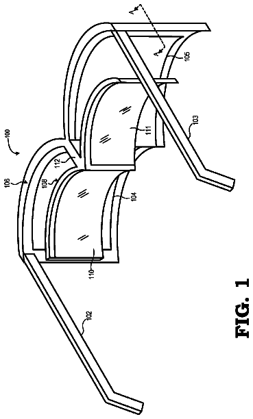
FIG. 1 is a diagram illustrating a wearable display system suitable for providing a virtual-reality (VR) image to a user, in an unfolded configuration, according to one embodiment;
FIG. 2 is a diagram of the wearable display system illustrated in FIG. 1 shown in the unfolded configuration and coupled to a peak of a baseball cap, according to one embodiment;
FIG. 3 is a diagram illustrating a front view of the wearable display system in a folded configuration, according to one embodiment;
FIG. 4 is a diagram illustrating a locking mechanism of the wearable VR system wherein hinged support members of the wearable display system are locked when in the unfolded configuration;
FIG. 5 is a diagram illustrating a top view of the wearable display system in a partially unfolded configuration, according to one embodiment;
FIG. 6 is a diagram illustrating the wearable display system in the unfolded configuration holding a display device, according to one embodiment;
FIG. 7A is a diagram illustrating a wearable display system, according to another embodiment;
FIG. 7B is a diagram of the wearable display system illustrated in FIG. 7A in an unfolded configuration, according to one embodiment;
FIG. 8 is a diagram illustrating a bottom view of a wearable display system having additional features for retaining the system on a user's head, in an unfolded configuration, according to an alternate embodiment;
FIGS. 9A-9C are diagrams illustrating respective rear, side, and top views of a wearable display system having additional features for retaining a display, according to an alternative embodiment;
FIGS. 10A-10C are diagrams illustrating respective rear, side, and top views of the wearable display system of FIGS. 9A-9C in a folded configuration;
FIG. 11 is a block diagram illustrating a display device, according to one embodiment; and
FIG. 12 is a flowchart illustrating a method of using a display system according to the disclosed embodiments.
Detailed description
The embodiments set forth subsequently represent the necessary information to enable those skilled in the art to practice the embodiments and illustrate the best mode of practicing the embodiments. Upon reading the following description in light of the accompanying drawing figures, those skilled in the art will understand the concepts of the disclosure and will recognize applications of these concepts not particularly addressed herein. It should be understood that these concepts and applications fall within the scope of the disclosure and the accompanying claims.
According to one embodiment, a wearable display system is disclosed. The system comprises a first lens sub-assembly defining a first optical path and a second lens sub-assembly defining a second optical path. The first and second lens sub-assemblies are disposed in a frame in respective first and second lens-holding sub-assemblies, with a bridge coupled therebetween. The frame also has a device holder configured to maintain a display of a device in the first and second optical paths. In one embodiment, the display is maintained within a predetermined range of distances and angles with respect to the first and second lens sub-assemblies. This arrangement permits the display, such as, for example, a smartphone display, to provide a specific image to each eye of a user. In some embodiments, different images can be provided to each eye independently from different portions of a common display, thereby enabling the user to perceive a three-dimensional (3D) image.
In this regard, FIG. 1 is a diagram illustrating a wearable display system 10 in an unfolded configuration, according to one embodiment. The system 10 comprises a first lens sub-assembly 12 A defining a first optical path 14 A and a second lens sub-assembly 12 B defining a second optical path 14 B. The first lens sub-assembly 12 A is disposed in a frame 16 in a first lens-holding sub-assembly 18 A, and the second lens sub-assembly 12 B is disposed in the frame 16 in a second lens-holding sub-assembly 18 B. The first and second lens-holding sub-assemblies 18 A, 18 B (generally, lens-holding sub-assemblies 18 ) are coupled to each other via a bridge 20 . The frame 16 also has a first device holder 22 A and a second device holder 22 B (generally, device holders 22 ) configured to maintain a display 24 of a display device 26 in the first and second optical paths 14 A, 14 B (generally, optical paths 14 ). In one embodiment, the display 24 is maintained within a predetermined range of distances Δ and angles θ with respect to the first and second lens sub-assemblies 12 A and 12 B (generally, lens sub-assemblies 12 ). In this embodiment, the display 24 has two distinct, non-overlapping portions 34 A, 34 B (generally, portions 34 ), each corresponding to the lens sub-assemblies 12 . This arrangement permits the display 24 independently to provide a specific image to eyes 30 A, 30 B (generally, eyes 30 ) of a user 32 (shown in FIG. 2 ), such as, for example, a 3D and/or virtual-reality (VR) image.
Each of the lens sub-assemblies 12 comprises a respective Fresnel lens system 36 A, 36 B (generally, Fresnel lens systems 36 ), each having at least one Fresnel lens 38 . In one embodiment, each Fresnel lens system 36 comprises two stacked Fresnel lenses 38 in a stacked relationship, such that each lens sub-assembly 12 refracts light twice. Using multiple, stacked Fresnel lenses may be selected based on, for example, the desired focal characteristics of the respective Fresnel lens system 36 and on dimensional and other design constraints. An example of a suitable Fresnel lens system 36 is described in U.S. patent application Ser. No. 14/858,733 (“FRESNEL LENS WITH REDUCED DRAFT FACET VISIBILITY”), filed Sep. 18, 2015, which is incorporated by reference in its entirety herein for this purpose.
The system 10 includes the frame 16 that includes the lens-holding sub-assemblies 18 . The lens-holding sub-assemblies 18 include the bridge 20 and a pair of lens holders 40 A, 40 B (generally, pair of lens holders 40 ) coupled to either side of the bridge 20 . The pair of lens holders 40 is configured to hold the lens sub-assemblies 12 .
The frame 16 includes the device holders 22 that are configured to hold the display device 26 and maintain the display device 26 within the predetermined range of distances Δ, such as a distance 28 , and within the predetermined range of angles with respect to the Fresnel lens systems 36 . The display device 26 may comprise any suitable computing device, such as, by way of non-limiting example, a smartphone or a computing tablet.
In one embodiment, the device holder 22 comprises a pair of support members 44 A, 44 B (generally, support members 44 ). The support members 44 are hingedly coupled to the lens-holding sub-assemblies 18 via respective hinges 46 A, 46 B. Each support member 44 comprises two display device grip members 48 A, 48 B. In some embodiments, the system 10 has a folded configuration and an unfolded configuration 50 . In the unfolded configuration 50 , each support member 44 extends in a plane 52 that is substantially perpendicular to a plane 54 of the lens-holding sub-assemblies 18 .
In one embodiment, each support member 44 may be biased toward the folded configuration. This biasing has two advantages. First, the risk of the system 10 unfolding during storage and/or transit, such as in a backpack or carrying case, is reduced. Second, the biasing causes the display device grip members 48 A, 48 B to exert opposing forces on the display device 26 when the display device 26 is disposed in the system 10 , thereby more securely gripping and holding the display device 26 in place within the system 10 during use. The biasing may be accomplished by one or more torsional springs (not shown) or other biasing components.
In one embodiment, peak attachment members 56 A, 56 B (generally, peak attachment members 56 ) are configured to be coupled to a peak of a hat. In one embodiment, the peak attachment members 56 comprise a pair of arms 58 A, 58 B that are coupled to the device holder 22 . In one embodiment, the peak attachment members 56 are configured, when coupled to a peak of a hat, to maintain the lens-holding sub-assemblies 18 within a predetermined range of distances Δ from the eyes 30 of the user 32 .
In this regard, FIG. 2 is a diagram of the system 10 shown in the unfolded configuration 50 coupled to a peak 60 of a baseball cap 62 being worn by a user 32 , thereby positioning the system 10 in front of the eyes 30 of the user 32 and in the field of view of the user 32 . In this view, it can also be seen that different portions 34 A, 34 B of the display 24 may be positioned in front of each eye 30 A, 30 B. As will be described in greater detail with respect to FIG. 6 , in some embodiments, different portions 34 of the display 24 are disposed in the separate optical paths 14 , thereby enabling the user 32 to perceive the different portions 34 of the display 24 through the Fresnel lens systems 36 as a single, 3D VR image.
The peak attachment members 56 , in this example embodied as the pair of arms 58 A, 58 B, are configured to maintain the lens-holding sub-assemblies 18 within the predetermined range of distances Δ from the eyes 30 of the user 32 (not illustrated) when coupled to the peak 60 . In some embodiments, the system 10 includes a shield, shroud, or sock, that blocks external light that may otherwise reflect inside of the Fresnel lens systems 36 . The shield (not shown) can also operate as a carrying case when not in operation.
FIG. 3 is a diagram illustrating a front view of the system 10 in a folded configuration 64 . In the folded configuration 64 , the support members 44 extend in the plane 52 that is substantially parallel to the plane 54 of the lens-holding sub-assemblies 18 . In the folded configuration 64 , the system 10 has a relatively flat form factor and can be easily and inconspicuously transported in the pocket of a jacket or shirt or in a purse.
FIG. 4 is a diagram illustrating a locking mechanism of the system 10 wherein the hinged support members 44 are locked when in the unfolded configuration 50 . In this embodiment, the locking mechanism comprises a tab 66 coupled to the frame 16 , which engages a member 68 of, for example, the support member 44 A to maintain the support member 44 A in the unfolded configuration 50 . The tab 66 inhibits folding of the support member 44 A without sufficient force, thus preventing accidental folding of the support member 44 A and adding rigidity to the system 10 when in the unfolded configuration 50 .
FIG. 5 is a diagram illustrating a top view of the system 10 in a partially unfolded configuration, according to one embodiment. Hinges 46 A, 46 B, respectively, allow support members 44 A, 44 B, to be swung from the folded configuration 64 to the unfolded configuration 50 .
In some embodiments, different images can be independently provided to each eye 30 . In this regard, FIG. 6 is a diagram illustrating the system 10 in the unfolded configuration 50 holding the display device 26 . In this view, it can be seen that different portions 34 A, 34 B of a display 24 have separate specific images for each optical path 14 A, 14 B, thereby enabling the user 32 to perceive the different portions 34 A, 34 B of the display 24 together as a 3D VR image. To provide these unique specific images to each eye 30 , the display device 26 may operate in a split-screen mode wherein a first portion 34 A provides imagery via the Fresnel lens system 36 A to a right eye 30 A of a user 32 (not shown) and a second portion 34 B provides imagery via the Fresnel lens system 36 B to the left eye 30 B of the user 32 (not shown). The display device 26 is held and maintained with respect to the lens-holding sub-assemblies 18 via the display device grip members 48 A, 48 B the desired distance 28 within a range of distances suitable for the display application of the system 10 .
FIGS. 7A and 7B are diagrams illustrating a wearable display system 10 - 1 according to another embodiment. The system 10 - 1 is substantially similar to the system 10 discussed previously unless otherwise discussed herein. FIG. 7A illustrates the system 10 - 1 with one support member 44 B- 1 in a fully extended state and one support member 44 A- 1 in between a folded configuration and an unfolded configuration. In this embodiment, the support members 44 A- 1 , 44 B- 1 are shaped to partially conform to the shape of the lens-holding sub-assemblies 18 A- 1 , 18 B- 1 , thereby allowing the system 10 - 1 to be more easily stored when the system 10 - 1 is in the folded configuration.
FIG. 8 is a diagram illustrating a bottom view of a wearable display system 10 - 2 having additional features for retaining the display 24 , according to an alternate embodiment. The system 10 - 2 is substantially similar to the system 10 discussed previously unless otherwise discussed herein.
In this embodiment as well, the system 10 - 2 includes a head support member 74 configured to extend around a user's head. In this embodiment, the head support member 74 is a strap attached to opposite attachment points 76 A- 2 , 76 B- 2 , on the respective support members 44 A- 2 , 44 B- 2 . It should be understood that additional or alternative attachment points may also be used. The strap may comprise any length, configuration, or material suitable for retaining the system 10 - 2 on the user's head during use and may also include a pad 78 for comfort.
FIGS. 9A-9C are diagrams illustrating respective rear, side, and top views of a wearable display system having additional features for retaining a display, according to an alternative embodiment. FIGS. 10A-10C are diagrams illustrating respective rear, side, and top views of the wearable display system of FIGS. 9A-9C in a folded configuration. The system 10 - 3 is substantially similar to the system 10 discussed previously unless otherwise discussed herein. In this embodiment, the components of the system 10 - 3 may be configured matingly to engage with each other in the folded configuration to make the system 10 - 3 more compact and portable when the system 10 - 3 is in the folded configuration.
In this regard, each display device grip member 48 A- 3 , 48 B- 3 has a respective lower support 80 A- 3 , 80 B- 3 configured to support the display device 26 against a downward force. In this embodiment, each display device grip member 48 A- 3 , 48 B- 3 also has a respective upper support 82 A- 3 , 82 B- 3 configured to support the display device 26 against an upward force. The lower supports 80 A- 3 , 80 B- 3 and upper supports 82 A- 3 , 82 B- 3 are separated from each other by a predetermined distance corresponding to a dimension of the display device 26 . In this manner, the display device 26 is retained in place while being worn by a user 32 , even while the user 32 is engaged in activity that causes the system 10 - 3 to bounce or shake.
As shown by FIGS. 9B and 9C , the support member 44 A- 3 also includes a front shield panel 84 A- 3 extending between the upper support 82 A- 3 and lower support 80 A- 3 . The support member 44 B- 3 includes a similar front shield panel 84 B- 3 . The purpose of the front shield panels 84 A- 3 , 84 B- 3 is to block ambient light and reduce glare on the display 24 of the display device 26 (not shown). In this embodiment, the system 10 - 3 also has a pair of rear shield panels 86 A- 3 , 86 B- 3 hingedly connected to the frame 16 and extending rearward towards the eyes 30 of the user 32 when the system 10 - 3 is in the unfolded configuration and being worn by the user 32 (not shown). The rear shield panels 86 A- 3 , 86 B- 3 help to block additional ambient light, thereby improving the immersiveness of the system 10 - 3 .
As shown by FIGS. 10A-10C , the front shield panels 84 A- 3 , 84 B- 3 cover the lens holders 40 A- 3 , 40 B- 3 from the front when the system 10 - 3 is in the folded configuration. In addition, the rear shield panels 86 A- 3 , 86 B- 3 rotate around the opposite side of the lens-holding sub-assemblies 18 A- 3 , 18 B- 3 to cover the lens holders 40 A- 3 , 40 B- 3 from the rear when the system 10 - 3 is in the folded configuration. In this manner, the front shield panels 84 A- 3 , 84 B- 3 and rear shield panels 86 A- 3 , 86 B- 3 protect the lenses 38 (not shown) from being damaged during storage or transport. In this embodiment, the front shield panel 84 A- 3 and rear shield panel 86 A- 3 rotate about a common hinge 46 A- 3 , and front shield panel 84 B- 3 and rear shield panel 86 B- 3 also rotate about a common hinge 46 B- 3 , but it should be understood that additional hinges may be employed in some embodiments.
The display device 26 may comprise any suitable computing device including, by way of non-limiting example, a smart phone, such as an Apple iPhone or Android-based smart phone, or a computing tablet. In this regard, FIG. 11 is a block diagram illustrating the display device 26 according to one embodiment. The display device 26 includes a processing device 88 , which comprises a processor or microprocessor. The display device 26 further includes a display 24 on which imagery can be presented. As discussed previously, in some embodiments, the display 24 generates a split-screen display such that different imagery is presented to each eye of a user. The processing device 88 is coupled to a memory 90 , in which, in one embodiment, software instructions may be stored to provide some or all of the functionality described herein. The display device 26 may include a storage device 92 and a communications interface 94 .
In some embodiments, the display device 26 may be programmed in accordance with certain development tools such as, by way of non-limiting example, Cardboard, Unity, Unreal, and/or Unigine development tools. In some embodiments, a distortion may be provided to the imagery that is displayed on the display 24 such that the imagery matches what the user would see in the real world. Thus, distorted imagery is provided to the display 24 , and the lens sub-assemblies 12 fix the imagery for viewing by the user.
The systems 10 to 10 - 3 provide a wide field of view (FOV) that is clear and in focus throughout the FOV. The systems 10 to 10 - 3 have a large exit pupil and thus do not have to be perfectly centered on the eyes of the user. The systems 10 to 10 - 3 can be used by users who wear glasses without any discomfort. When in a folded configuration, the systems 10 to 10 - 3 are relatively thin and fit easily within a pocket or purse.
The systems 10 to 10 - 3 may present games, including 3D games, movies, or the like. The display device 26 may include, in some embodiments, an accelerometer or other motion-sensitive device such that movements of the user's head can determine which portions of a virtual world are presented to the user. Thus, the user, simply by turning his head, can view different portions of the virtual world.
FIG. 12 is a flowchart illustrating a method 100 of using a display system according to the disclosed embodiments. The method 100 comprises positioning a frame, such as, for example, frame 16 with lens-holding sub-assemblies 18 , of a wearable display system in a field of view of a user (block 102 ). The method 100 further comprises disposing a display of a device, such as display 24 , in a device holder of the wearable display system (block 104 ), such that the display is maintained within a predetermined range of distances with respect to the first lens sub-assembly and the second lens sub-assembly, and the display is maintained within a predetermined range of angles with respect to the first lens sub-assembly and the second lens sub-assembly. The method further comprises delivering images to a user wearing the system via the lens-holding sub-assemblies (block 106 ).
Those skilled in the art will recognize improvements and modifications to the preferred embodiments of the disclosure. All such improvements and modifications are considered within the scope of the concepts disclosed herein and the claims that follow.
 Lapsed, fee not paid8 drawings