 Lapsed, fee not paid12 drawings
Industrial Equipment · US 9,938,802 B2
Temporarily impermeable sleeve for running a well component in hole
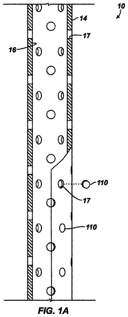
An apparatus for installation in a borehole comprises a well component and a sleeve.
US 9,938,876 B2 · Assignee: Toyota Jidosha Kabushiki Kaisha · Inventors: Shirasawa; Takeru et al.
Sheet 1 of 11 from the published document. All sheets in the USPTO PDF
When an integrated value of a determination value correlated with a command value for an amount of supply of a reducing agent at the time of the command value being larger than a command supply amount threshold value reaches an integration threshold value, a determination is made that a diagnosis condition is satisfied, and an abnormality in the supply of the reducing agent is diagnosed based on an integrated value of the command value for the amount of supply of the reducing agent and an integrated value of an estimated value of the amount of supply of the reducing agent, whereas in cases where a period of time in which the diagnosis condition is not satisfied is longer than a time period threshold value, an interval of supply of the reducing agent is extended.
Field of the Disclosure The present disclosure relates to an abnormality diagnosis device for an exhaust gas purification apparatus in an internal combustion engine. Background There has been known an NOx selective catalytic reduction catalyst (hereinafter, also referred to simply as an “NOx catalyst”) which purifies (removes or reduces) NOx contained in an exhaust gas from an internal combustion engine by using ammonia as a reducing agent. At the upstream side of this NOx catalyst, there is arranged an addition valve or the like which serves to add ammonia or a precursor of ammonia into the exhaust gas. As the precursor of ammonia, there can be mentioned urea, for example. Hereinafter, the precursor of ammonia or ammonia is also collectively referred to as “a reducing agent”. Here, there has been known a technology in which a determination of whether clogging has occurred in an addition
1 of 11 drawing sheets so far from the published document, cropped to the drawing. Every sheet is in the USPTO PDF.
What the patent claimed, word for word. All of it is now free to use.
This application claims priority to Japanese Patent Application No. 2016-030144 filed on Feb. 19, 2016, and Japanese Patent Application No. 2016-224211 filed on Nov. 17, 2016 the entire contents of which are incorporated by reference herein.
Field of the Disclosure
The present disclosure relates to an abnormality diagnosis device for an exhaust gas purification apparatus in an internal combustion engine.
Background
There has been known an NOx selective catalytic reduction catalyst (hereinafter, also referred to simply as an “NOx catalyst”) which purifies (removes or reduces) NOx contained in an exhaust gas from an internal combustion engine by using ammonia as a reducing agent. At the upstream side of this NOx catalyst, there is arranged an addition valve or the like which serves to add ammonia or a precursor of ammonia into the exhaust gas. As the precursor of ammonia, there can be mentioned urea, for example. Hereinafter, the precursor of ammonia or ammonia is also collectively referred to as “a reducing agent”.
Here, there has been known a technology in which a determination of whether clogging has occurred in an addition valve is made by using the value of pressure in a reducing agent passage at the time of returning a reducing agent to a tank (for example, refer to patent literature 1). In addition, in the patent literature 1, it is also further described that the determination of whether clogging has occurred in the addition valve is made based on an amount of pressure drop in the reducing agent passage at the time when the reducing agent was supplied. CITATION LIST Patent Literature
Patent Literature 1: Japanese patent laid-open publication No. 2011-117440
Patent Literature 2: Japanese patent laid-open publication No. 2008-202469
Patent Literature 3: Japanese patent laid-open publication No. 2008-180193 SUMMARY Technical Problem
In cases where the determination of whether clogging has occurred in the addition valve is made by using the value of pressure in the reducing agent passage at the time of returning the reducing agent to the tank, the reducing agent can not be supplied from the addition valve, and hence, there is a fear that the rate of NOx reduction (NOx reduction rate) may drop due to shortage of the reducing agent during the operation of the internal combustion engine. On the other hand, in cases where the determination of whether clogging has occurred in the addition valve is made based on the amount of pressure drop at the time of the supply of the reducing agent, the amount of pressure drop is small when the amount of supply of the reducing agent is small, so there is a fear that the accuracy of the determination may decrease. In these cases, when an abnormality diagnosis of a reducing agent supply device is not carried out, an opportunity to carry out the abnormality diagnosis will be reduced.
Accordingly, the present disclosure has for its object to increase an opportunity to diagnose an abnormality in the supply of a reducing agent. Solution to Problem
In order to achieve the above-mentioned object, the present disclosure resides in an abnormality diagnosis device for an exhaust gas purification apparatus in an internal combustion engine, which is to diagnose an abnormality of said exhaust gas purification apparatus which is provided with: an NOx selective catalytic reduction catalyst that is arranged in an exhaust passage of the internal combustion engine and configured to reduce NOx by using a reducing agent; an addition valve configured to supply the reducing agent into said exhaust passage at the upstream side of said NOx selective catalytic reduction catalyst; a pump configured to deliver an amount of reducing agent to said addition valve according to a rotational speed thereof; a reducing agent passage that connects said pump and said addition valve with each other for flowing the reducing agent therethrough; and a pressure sensor configured to detect a pressure of the reducing agent; said abnormality diagnosis device comprising: a controller configured to: calculate a command value for an amount of supply of the reducing agent to be given to said addition valve at each interval of supply of the reducing agent, based on a total amount of an amount of NOx which flows into said NOx selective catalytic reduction catalyst at each interval of supply of the reducing agent; calculate an estimated value of the amount of supply of the reducing agent from said addition valve at each interval of supply of said reducing agent based on the pressure detected by said pressure sensor or a physical quantity correlated with said pressure; and make a determination that a diagnosis condition, which is a condition for diagnosing an abnormality in the supply of the reducing agent, is satisfied, when an integrated value of a determination value correlated with the command value of the amount of supply of the reducing agent calculated by said controller at the time when said command value is larger than a command supply amount threshold value reaches an integration threshold value, and diagnoses an abnormality in the supply of the reducing agent, based on an integrated value of the command value of the amount of supply of the reducing agent calculated by said controller at the time when said command value is larger than said command supply amount threshold value, and an integrated value of the estimated value of the amount of supply of the reducing agent calculated by said controller, at the same time as when the command value of the amount of supply of the reducing agent calculated by said controller is larger than said command supply amount threshold value, wherein said controller configured to extend the interval of supply of said reducing agent in the case where a period of time in which said diagnosis condition is not satisfied is longer than a time period threshold value, more than in the case where said diagnosis condition is satisfied, or in the case where the period of time in which said diagnosis condition is not satisfied is equal to or less than said time period threshold value.
The controller diagnoses that there is an abnormal, in cases where the estimated value of the amount of supply of the reducing agent estimated by the controller is largely apart from the command value of the amount of supply of the reducing agent calculated by the controller, when the diagnosis condition is satisfied. Here, note that at the time of carrying out the abnormality diagnosis, the accuracy of the abnormality diagnosis is enhanced by making a comparison between the integrated value of the command value and the integrated value of the estimated value in the same period of time, but the estimated value and the command value for the amount of supply of the reducing agent in one supply of the reducing agent can be included in these integrated values.
The diagnosis condition is set as a condition for enhancing the accuracy of the abnormality diagnosis. Here, in cases where the command value of the amount of supply of the reducing agent is small, the amount of reducing agent to be actually supplied becomes small, so the estimated value of the amount of supply of the reducing agent also becomes small. In this case, the difference in the amount of supply of the reducing agent due to the presence or absence of an abnormality becomes small. For this reason, the amount of supply of the reducing agent becomes easily affected by an error or variation of the rotational speed of the pump, and hence, the estimated value of the amount of supply of the reducing agent calculated by the controller becomes unable to reflect the actual amount of supply of the reducing agent in an accurate manner. Accordingly, when an abnormality diagnosis is carried out using the command value and the estimated value of the amount of supply of the reducing agent at this time, there is a fear that the accuracy of the abnormality diagnosis may be reduced. For this reason, the accuracy of the abnormality diagnosis is enhanced by making a comparison between the integrated value of the command value and the integrated value of the estimated value of the amount of supply of the reducing agent at the time when the command value of the amount of supply of the reducing agent is larger than the command supply amount threshold value. Accordingly, the command supply amount threshold value is a command value for the amount of supply of the reducing agent at the time of the supply of the reducing agent in the case where the accuracy of the abnormality diagnosis falls within a suitable limit.
In addition, the larger the integrated value of the command value of the amount of supply of the reducing agent at the time when the command value of the amount of supply of the reducing agent is larger than the command supply amount threshold value, the larger the difference between the integrated value of the command value and the integrated value of the estimated value of the amount of supply of the reducing agent becomes in an abnormal case and in a normal case, as a result of which it is possible to enhance the accuracy of the abnormality diagnosis. Accordingly, the determination value is set as a value correlated with the command value of the amount of supply of the reducing agent at the time when the command value of the amount of supply of the reducing agent is larger than the command supply amount threshold value. That is, what is used for the abnormality diagnosis is not a value obtained by merely integrating the command value of the amount of supply of the reducing agent, but the integrated value of the command value of the amount of supply of the reducing agent at the time when the command value of the amount of supply of the reducing agent is larger than the command supply amount threshold value, and hence, a determination is carried out using a determination value correlated with the command value of the amount of supply of the reducing agent at the time when the command value of the amount of supply of the reducing agent is larger than the command supply amount threshold value. Then, when the integrated value of the determination value reaches the integration threshold value, the accuracy of the abnormality diagnosis is assumed to be high, so a determination is made that the diagnosis condition has been satisfied. Here, note that the larger the command value, the larger the determination value may be made. The integration threshold value is decided in such a manner that the accuracy of the abnormality diagnosis falls within a suitable range.
The accuracy in the abnormality diagnosis can be enhanced by carrying out the abnormality diagnosis in the case where the diagnosis condition is satisfied, as described above. However, the period of time in which the diagnosis condition is not satisfied becomes long, depending on the operating state of the internal combustion engine. Accordingly, when the period of time in which the diagnosis condition is not satisfied becomes equal to or more than the time period threshold value, the controller extends the interval of supply of the reducing agent. The longer the interval of supply of the reducing agent, the more becomes the total amount of the amount of NOx flowing into the NOx selective catalytic reduction catalyst by the time the reducing agent is supplied, so that the command value for the amount of supply of the reducing agent per one time becomes larger. That is, the longer the interval of supply of the reducing agent, the larger becomes the command value of the amount of supply of the reducing agent. Thus, the amount of reducing agent to be supplied at the time of the next supply of the reducing agent is increased by extending the interval of supply of the reducing agent. That is, the command value of the amount of supply of the reducing agent can be made to increase. In this manner, too, the reducing agent can be supplied according to the amount of NOx in the exhaust gas, so that the decrease of the NOx removal or reduction rate can be suppressed. Then, due to the increase in the amount of supply of the reducing agent per one time, the command value of the amount of supply of the reducing agent becomes easy to exceed the command supply amount threshold value, so that the diagnosis condition can be easily satisfied, thus making it possible to start the abnormality diagnosis more quickly. Accordingly, the opportunity for the abnormality diagnosis can be increased. Here, note that the time period threshold value is set so as to satisfy the frequency of the abnormality diagnosis as required.
Moreover, in cases where the period of time in which said diagnosis condition is not satisfied is longer than said time period threshold value, said controller may extend the interval of supply of said reducing agent in the case where the temperature of said NOx selective catalytic reduction catalyst is less than a predetermined temperature, more than in the case where said diagnosis condition is satisfied, or in the case where the period of time in which said diagnosis condition is not satisfied is equal to or less than said time period threshold value, whereas said controller may make the interval of supply of said reducing agent in the case where the temperature of said NOx selective catalytic reduction catalyst is equal to or higher than said predetermined temperature, equal to that in the case where said diagnosis condition is satisfied, or in the case where the period of time in which said diagnosis condition is not satisfied is equal to or less than said time period threshold value.
When the temperature of the NOx catalyst becomes too high, an adsorbable amount of the reducing agent will become small, and hence, if the frequency of supply of the reducing agent is not enhanced, there will be a fear that the reducing agent for reducing NOx may run short. At this time, if the interval of supply of the reducing agent is extended, the reducing agent may run short, and the NOx reduction rate may decrease or become low. In contrast to this, if the interval of supply of the reducing agent is not extended in the case where the temperature of the NOx catalyst is equal to or higher than the predetermined temperature, the reducing agent can be suppressed from running short in the NOx catalyst, thus making it possible to suppress the NOx reduction rate from decreasing. That is, in the case where the temperature of the NOx catalyst is equal to or higher than the predetermined temperature, priority is given to suppressing the decrease of the exhaust gas purification performance over carrying out abnormality diagnosis. The predetermined temperature is a temperature at which the NOx reduction rate becomes lower than an allowable range when the interval of supply of the reducing agent is extended. Advantageous Effects
According to the present disclosure, it is possible to increase an opportunity to diagnose an abnormality in the supply of a reducing agent.
Further features of the present disclosure will become apparent from the following description of exemplary embodiments with reference to the attached drawings.
FIG. 1 is a view showing the schematic construction of an internal combustion engine as well as its intake and exhaust systems according to embodiments of the present disclosure.
FIG. 2 is a block diagram for obtaining a command supply amount.
FIG. 3 is a flow chart showing a flow for reducing agent supply control.
FIG. 4 is a time chart showing the change over time of the rotational speed of a pump when the reducing agent is supplied from an addition valve.
FIG. 5 is a view showing the relation between a rotational speed counter and an estimated amount of supply.
FIG. 6 is a view showing the relation between the command supply amount and a cycle counter at the time of supplying the reducing agent.
FIG. 7 is a time chart showing the change over time of the rotational speed of the pump in cases where the command supply amount is relatively small.
FIG. 8 is a time chart showing the change over time of the rotational speed of the pump in cases where the command supply amount is relatively large.
FIG. 9 is a flow chart showing a flow for abnormality diagnosis of a reducing agent supply device according to a first embodiment.
FIG. 10 is a flow chart showing a flow for reducing agent supply control in cases where an interval of supply of the reducing agent is extended.
FIG. 11 is a flow chart showing a flow for abnormality diagnosis of a reducing agent supply device according to a second embodiment.
Hereinafter, the best modes for carrying out the present disclosure will be exemplarily described in detail based on preferred embodiments with reference to the attached drawings. However, the dimensions, materials, shapes, relative arrangements and so on of component parts described in the embodiments are not intended to limit the scope of the present disclosure to these alone in particular as long as there are no specific statements. First Embodiment
FIG. 1 is a view showing the schematic construction of an internal combustion engine as well as its intake and exhaust systems according to a first embodiment of the present disclosure. The internal combustion engine denoted by 1 is a diesel engine for driving a vehicle. However, the internal combustion engine 1 may be a gasoline engine. An exhaust passage 2 is connected to the internal combustion engine 1 . In the exhaust passage 2 , there is arranged an NOx selective catalytic reduction catalyst 3 (hereinafter referred to as an NOx catalyst 3 ) which serves to selectively reduce NOx in an exhaust gas with the use of ammonia as a reducing agent.
A reducing agent supply device 4 for supplying the reducing agent to the NOx catalyst 3 is mounted on the exhaust passage 2 at the upstream side of the NOx catalyst 3 . The reducing agent supply device 4 is provided with a tank 41 , an addition valve 42 , a reducing agent passage 43 , a pump 44 , a pressure sensor 45 , a return passage 47 , and a check valve 48 .
The tank 41 stores urea water. The addition valve 42 is mounted on the exhaust passage 2 at a location upstream of the NOx catalyst 3 , and serves to inject the urea water. The reducing agent passage 43 connects the tank 41 and the addition valve 42 with each other, and circulates the urea water therebetween. The urea water supplied from the addition valve 42 is hydrolyzed into ammonia by the heat of the exhaust gas or the heat from the NOx catalyst 3 , and the ammonia thus generated is adsorbed to the NOx catalyst 3 . This ammonia is used as the reducing agent in the NOx catalyst 3 . Here, note that in the following, the ammonia and the urea water are collectively referred to as the reducing agent.
The pump 44 is arranged at a location where the reducing agent passage 43 is connected to the tank 41 , and the pump 44 serves to deliver the reducing agent. Here, note that the pump 44 may also be arranged in the interior of the tank 41 . The pump 44 is an electric pump, and is rotated by supplying electric power thereto. This pump 44 can change the amount of delivery of the reducing agent by changing the rotational speed thereof. With this, the pressure of the reducing agent can be adjusted. In addition, the pressure sensor 45 for detecting the pressure of the reducing agent is mounted on the reducing agent passage 43 . A pump rotational speed sensor 46 for detecting the rotational speed (this may also be as the number of rotations per minute) of the pump 44 is mounted on the pump 44 . Also, the return passage 47 connects the reducing agent passage 43 and the tank 41 with each other. The return passage 47 is a passage for returning a part of the reducing agent which exceeds a fixed pressure, among the reducing agent delivered from the pump 44 , to the tank 41 through the check valve 48 . The check valve 48 is arranged in the return passage 47 , and when the pressure in the return passage 47 becomes the fixed pressure, the check valve 48 is opened to circulate the reducing agent from the side of the reducing agent passage 43 to the side of the tank 41 .
Moreover, at the upstream side of the addition valve 42 , there is arranged an upstream side NOx sensor 11 for detecting the concentration of NOx in the exhaust gas flowing into the NOx catalyst 3 . Also, at the downstream side of the NOx catalyst 3 , there are arranged a downstream side NOx sensor 12 for detecting the concentration of NOx in the exhaust gas flowing out of the NOx catalyst 3 and a temperature sensor 13 for detecting the temperature of the exhaust gas.
In addition, an intake passage 6 is connected to the internal combustion engine 1 . A throttle valve 7 for regulating an amount of intake air to be supplied to the internal combustion engine 1 is arranged in the middle of the intake passage 6 . Also, an air flow meter 16 for detecting the amount of intake air in the internal combustion engine 1 is mounted on the intake passage 6 at a location upstream of the throttle valve 7 .
Then, an ECU 10 , which is an electronic control unit, is provided in combination with the internal combustion engine 1 . The ECU 10 controls the operating state of the internal combustion engine 1 , an exhaust gas purification apparatus, and so on. A crank position sensor 14 and an accelerator opening sensor 15 , in addition to the above-mentioned upstream side NOx sensor 11 , the downstream side NOx sensor 12 , the temperature sensor 13 and the air flow meter 16 , the pressure sensor 45 , the pump rotational speed sensor 46 , are electrically connected to the ECU 10 , so that the output values of these individual sensors are passed or transmitted to the ECU 10 .
The ECU 10 is able to grasp the operating state of the internal combustion engine 1 , such as the engine rotational speed based on the detection of the crank position sensor 14 , the engine load based on the detection of the accelerator opening sensor 15 , etc. Here, note that in this embodiment, the NOx in the exhaust gas flowing into the NOx catalyst 3 is able to be detected by the upstream side NOx sensor 11 , but the NOx contained in the exhaust gas discharged from the internal combustion engine 1 (the exhaust gas before being purified or reduced in the NOx catalyst 3 , i.e., the exhaust gas flowing into the NOx catalyst 3 ) has relation with the operating state of the internal combustion engine, and hence, is also able to be estimated based on the above-mentioned operating state of the internal combustion engine 1 . In addition, the ECU 10 is able to estimate the temperature of the NOx catalyst 3 based on the temperature of the exhaust gas detected by the temperature sensor 13 . Moreover, it is also possible to estimate the temperature of the NOx catalyst 3 based on the operating state of the internal combustion engine 1 . On the other hand, the throttle valve 7 , the addition valve 42 and the pump 44 are connected to the ECU 10 through electrical wiring, so that these valves and pump are controlled by means of the ECU 10 .
The ECU 10 controls to supply the reducing agent from the addition valve 42 so that the amount of adsorption of ammonia in the NOx catalyst 3 becomes a target value of the amount of adsorption of ammonia in the NOx catalyst 3 (hereinafter, also referred to as a target amount of adsorption). In this case, the ECU 10 calculates an amount of reducing agent which is added from the addition valve 42 (hereinafter, also referred to as an amount of supply of the reducing agent) so as to make the amount of adsorption of ammonia of the NOx catalyst 3 equal to the target amount of adsorption, by compensating for an amount of ammonia which has been consumed in order to reduce NOx in the NOx catalyst 3 (hereinafter, also referred to as an amount of ammonia consumption) in a period of time from a starting point in time of the last supply of the reducing agent until a starting point in time of the current supply of the reducing agent (hereinafter, also referred to as an interval of supply), and an amount of ammonia which has been desorbed from the NOx catalyst 3 and decreased without reducing NOx (hereinafter, also referred to as an amount of desorption of ammonia). For this reason, the ECU 10 repeatedly calculates the amount of supply of the reducing agent based on an amount of NOx flowing into the NOx catalyst 3 (hereinafter, also referred to as an amount of incoming NOx), the temperature of the NOx catalyst 3 (hereinafter, also referred to as the catalyst temperature), and the target amount of adsorption in the NOx catalyst 3 , in each of a plurality of operation periods included in the interval of supply, and integrates the amounts of supply of the reducing agent calculated during the interval of supply. Then, the integrated value of the amounts of supply of the reducing agent at the starting point in time of the supply of the reducing agent becomes a command value to be given to the addition valve 42 from the ECU 10 . This command value for the amount of supply of the reducing agent is an amount of reducing agent which should actually be supplied from the addition valve 42 . The amount of supply of the reducing agent, the valve opening period of time of the addition valve 42 , and the pressure of the reducing agent are correlated with one another, and hence, if such a correlation has been obtained in advance by experiments, simulations, or the like, the valve opening period of time of the addition valve 42 can be decided from the amount of supply of the reducing agent to be calculated and the pressure of the reducing agent to be detected. The ECU 10 controls to supply the reducing agent, by making the addition valve 42 open for only a period of time corresponding to the amount of supply of the reducing agent. Here, note that in the following, the command value for the amount of supply of the reducing agent is also referred to as a command supply amount.
The supply of the reducing agent is carried out in each predetermined period of time. That is, the interval of supply of the reducing agent is set to a predetermined period of time. Accordingly, the amount of supply of the reducing agent integrated in the predetermined period of time from the starting time of the last supply of the reducing agent serves as a command value for the amount of supply of the reducing agent. Here, the ECU 10 carries out an abnormality diagnosis of the reducing agent supply device 4 , but may extend the interval of supply of the reducing agent at the time of carrying out this abnormality diagnosis. Here, note that the predetermined period of time, which is the interval of supply of the reducing agent before extended, is set as a normal predetermined period of time. When the predetermined period of time is made too long, there is a fear that the NOx reduction rate may be decreased due to the shortage of the reducing agent in the NOx catalyst 3 . On the other hand, a minimum amount in which the reducing agent can be injected with a high degree of accuracy is set for the addition valve 42 . This minimum amount is decided by the performance of the addition valve 42 . Accordingly, the normal predetermined period of time is decided as the interval of supply of the reducing agent at which the decrease of the NOx removal or reduction rate is suppressed, and at which the amount of supply of the reducing agent can become equal to or more than the above-mentioned minimum amount. The normal predetermined period of time is decided as an appropriate value of the interval of supply of the reducing agent, by means of experiments, simulations, or the like.
FIG. 2 is a block diagram for obtaining the command supply amount. This FIG. 2 images the functions which are achieved by means of the processing in the ECU 10 . The amount of ammonia consumption can be obtained based on the amount of incoming NOx, the catalyst temperature, and the target amount of adsorption. Also, the amount of desorption of ammonia can be obtained based on the catalyst temperature and the target amount of adsorption. The amount of NOx flowing into the NOx catalyst 3 in each operation period of the ECU 10 is associated with the concentration of NOx in the exhaust gas and the flow rate of the exhaust gas, and the flow rate of the exhaust gas is associated with the amount of intake air detected by the air flow meter 16 . Accordingly, the amount of NOx flowing into the NOx catalyst 3 in each operation period of the ECU 10 can be calculated based on the detected value of the upstream side NOx sensor 11 and the detected value of the air flow meter 16 . Here, note that, the detected value of the upstream side NOx sensor 11 and the detected value of the air flow meter 16 are handled on the assumption that these values at the time of the current calculation continue from the time of the last calculation to the time of the current calculation, or on the assumption that these values at the time of the last calculation continue from the time of the last calculation to the time of the current calculation. Otherwise, an average value of the detected value of the upstream side NOx sensor 11 and an average value of the detected value of the air flow meter 16 from the time of the last calculation to the time of the current calculation may be obtained, respectively, and may be handled on the assumption that these average values continue from the time of the last calculation to the time of the current calculation.
Moreover, the catalyst temperature is can be detected by the temperature sensor 13 . The temperature of the NOx catalyst 3 at the time of the last calculation, the temperature of the NOx catalyst 3 at the time of the current calculation, or an average value of the temperature of the NOx catalyst 3 from the time of the last calculation to the time of the current calculation can be used for the catalyst temperature used at the time of calculating the command supply amount. Further, the target value of the amount of adsorption of ammonia decided based on the operating state of the internal combustion engine 1 at the time of the current calculation or the target value of the amount of adsorption of ammonia decided based on the operating state of the internal combustion engine 1 at the time of the last calculation can be used for the target amount of adsorption. The target amount of adsorption can be obtained in advance by experiments, simulations, or the like as a value which can secure a desired NOx reduction rate in the NOx catalyst 3 , and which can suppress an amount of ammonia flowing out from the NOx catalyst 3 within an allowable range. The higher the catalyst temperature, the more becomes the amount of ammonia consumption, and the more the amount of incoming NOx, the more becomes the amount of ammonia consumption, and the more the target amount of adsorption, the more becomes the amount of ammonia consumption. The higher the catalyst temperature, the more becomes the amount of ammonia desorption, and the more the target amount of adsorption, the more becomes the amount of ammonia desorption. Then, the ECU 10 calculates at each operation period thereof an amount of supply of the reducing agent (hereinafter, also referred to as an operation period supply amount), by setting, as an amount of ammonia to be supplied, a total value (amount) of the amount of ammonia consumption in the NOx catalyst 3 and the amount of desorption of ammonia in the NOx catalyst 3 , and integrates this value in the period of time of the interval of supply. Then, an integrated value of the operation period supply amount at the point in time of reaching the time to supply the reducing agent serves as the command supply amount.
FIG. 3 is a flow chart showing a flow or routine for reducing agent supply control. This flow chart is carried out by means of the ECU 10 at a predetermined operation period.
In step S 101 , the amount of incoming NOx, the catalyst temperature, and the target amount of adsorption are acquired. As explained in FIG. 2 , the amount of incoming NOx, the catalyst temperature and the target amount of adsorption are required in order to calculate the amount of supply of the reducing agent, so the values of these factors acquired as mentioned above are obtained.
In step S 102 , the amount of consumption of ammonia is calculated. That is, the amount of consumption of ammonia is calculated based on the amount of incoming NOx, the catalyst temperature, and the target amount of adsorption.
In step S 103 , the amount of desorption of ammonia is calculated. That is, the amount of desorption of ammonia is calculated based on the catalyst temperature and the target amount of adsorption.
In step S 104 , the operation period supply amount corresponding to the amount of adsorption of ammonia in the NOx catalyst 3 decreased from the target amount of adsorption is calculated in the period of time from the time of execution of the flow chart in the last operation period to the time of execution of the flow chart in the current operation period. The operation period supply amount is calculated by using the amount of ammonia consumption and the amount of desorption of ammonia. The relation between the amount of adsorption of ammonia decreased from the NOx catalyst 3 , and the amount of supply of the reducing agent (the urea water) has been obtained in advance by experiments, simulations, or the like.
In step S 105 , the operation period supply amount calculated in step S 104 at the time of the current execution of the flow chart is added to the operation period supply amount calculated in step S 105 at the time of execution of the flow chart in the last operation period. That is, the operation period supply amount is integrated. Here, note that in this embodiment, the ECU 10 carries out the processing of step S 105 , and thus functions as a controller in the present disclosure.
In step S 106 , it is determined whether the period of time elapsed from the starting point in time of the last supply of the reducing agent is equal to or longer than the predetermined period of time. The predetermined period of time is a value which has been set in advance as the interval of supply of the reducing agent. The elapsed period of time from the starting point in time of the last supply of the reducing agent is counted by the ECU 10 . In this step S 106 , it is determined whether it is the time to supply the reducing agent. In cases where an affirmative determination is made in step S 106 , the flow or routine of the flow chart in FIG. 3 goes to step S 107 , whereas in cases where a negative determination is made, this routine is ended.
In step S 107 , the reducing agent is supplied from the addition valve 42 . The ECU 10 sets the integrated value of the operation period supply amount calculated in step S 105 as the command supply amount, and causes the addition valve 42 to open only for the period of time corresponding to this command supply amount. The relation between the command supply amount and the valve opening time of the addition valve 42 has been obtained in advance by experiments, simulations or the like, and stored in the ECU 10 . In addition, the counting of a new elapsed period of time begins from the starting point in time of the supply of the reducing agent, for the next supply of the reducing agent. When the processing of step S 107 ends, the routine goes to step S 108 , where the integrated value of the operation period supply amount is reset. However, the command supply amount is stored in the ECU 10 .
In this manner, the command supply amount at the point in time of the supply of the reducing agent can be calculated by first calculating the operation period supply amount until the predetermined period of time elapses, and then integrating this operation period supply amount. Then, according to this command supply amount, the reducing agent is supplied in each predetermined period of time.
Further, the ECU 10 carries out an abnormality diagnosis of the reducing agent supply device 4 by making a comparison between the command supply amount and the estimated value of the amount of supply of the reducing agent (hereinafter, referred to as the estimated amount of supply). For this purpose, the ECU 10 obtains the estimated amount of supply based on an integrated value of an amount of change of the rotational speed of the pump 44 . Here, the ECU 10 carries out the feedback control of the rotational speed of the pump 44 so that the pressure in the reducing agent passage 43 comes close to the predetermined pressure. The predetermined pressure is a pressure of the reducing agent suitable for supplying the reducing agent from the addition valve 42 . When the reducing agent is supplied from the addition valve 42 , the pressure in the reducing agent passage 43 will drop. In cases where a pressure drop in the reducing agent passage 43 is detected by the pressure sensor 45 , the pressure in the reducing agent passage 43 is quickly raised by increasing the rotational speed of the pump 44 . Here, the amount of reducing agent actually supplied from the addition valve 42 is in correlation with the amount of pressure drop in the reducing agent passage 43 . That is, the more the actual amount of supply of the reducing agent, the larger becomes the amount of pressure drop in the reducing agent passage 43 , and hence, if such a relation has been obtained in advance by experiments, simulations, or the like, the estimated amount of supply can be obtained based on the amount of pressure drop in the reducing agent passage 43 .
In addition, the rotational speed of the pump 44 is controlled in a feedback manner based on the pressure in the reducing agent passage 43 , so the amount of pressure drop in the reducing agent passage 43 and the amount of rise in the rotational speed of the pump 44 are correlated with each other. That is, the more the amount of supply of the reducing agent from the addition valve 42 , the larger becomes the amount of pressure drop in the reducing agent passage 43 , and so, the larger the rotational speed of the pump 44 is made. Accordingly, the estimated amount of supply can also be obtained based on the amount of change of the rotational speed of the pump 44 which is in correlation with the pressure of the reducing agent. For this reason, in this embodiment, the estimated amount of supply is obtained based on the amount of change of the rotational speed of the pump 44 due to the delivery of the reducing agent. For the purpose of obtaining the estimated amount of supply, the ECU 10 is provided with a rotational speed counter for integrating the amount of change of the rotational speed of the pump 44 . It can be said that the amount of change of the rotational speed of the pump 44 is a physical quantity correlated with the pressure of the reducing agent detected by the pressure sensor 45 .
The description continues in the full USPTO document.
About 6,870 words. The USPTO PDF has it with every drawing.
Fees are due 3.5, 7.5 and 11.5 years after grant. This patent expired on April 10, 2026, so the fee marked "not paid" was the one that went unpaid.
ABNORMALITY DIAGNOSIS DEVICE FOR EXHAUST GAS PURIFICATION APPARATUS IN INTERNAL COMBUSTION ENGINE
Filed Feb 2017 · published Aug 2017Abnormality diagnosis device for exhaust gas purification apparatus in internal combustion engine
Filed Feb 2017 · granted Apr 2018Earlier publications, parents and continuations. None of them can still be enforced, or this patent would not be listed.
Prior art cited by the examiner or applicant. Useful when you check your own idea for novelty.
Everything on this page comes from the documents linked above.


