BACKGROUND Field of the Present Disclosure
The present invention relates to a guide assembly for guiding a casing used in forming a sheathing wall in a ground and a method for forming a sheathing wall in a ground using the same. More particularly, the present invention relates to a guide assembly for guiding a casing used in forming a sheathing wall in a ground where the guide assembly is reusable and enables improved water blocking. Further, the present invention relates to a method for forming a sheathing wall in a ground using the guide assembly. Discussion of Related Art
Generally, in order to construct various underground facilities, the H-beam should be buried underground or the sheathing wall made of concrete should be installed in the ground. A variety of construction methods and excavators have been used to embed the H-beams therein or to install the concrete sheathing wall therein. In addition, in order to construct various structures such as an apartment, a building, or a bridge, a foundation trench construction is performed by excavating the ground by a predetermined depth.
The foundation trench construction is carried out in advance in order to provide an installation space of a structure in a building construction and a civil engineering work. At this time, it is general to install the sheathing wall so that a surrounding ground does not collapse toward the foundation trench. This sheathing wall is constructed to withstand an earth pressure of the surrounding ground.
When, in the foundation trench construction, the underground water or infiltrating water flows through the excavated ground and then is erupted from the foundation trench, there is a risk that a strength and safety of the structure to be constructed may be detrimentally affected. Therefore, the sheathing wall should have a water blocking function to prevent the water passing through the surrounding ground from flowing into the installation space of the structure, in addition to the ability to withstand the earth pressure of the surrounding ground.
One of sheathing wall forming methods is a cast-in place pile CIP method. In this CIP method, a hole of a predetermined size is drilled in the ground, and thereafter, a concrete or a mortar is filled in the hole to form a columnar pile. Further, a plurality of piles are connected to each other in a line to form a continuous-pile type sheathing wall. Such continuous-pile type sheathing wall is currently formed by various construction methods.
In one example of forming such continuous-pile type sheathing wall, a plurality of tubular casings are inserted at a certain depth in the ground and are arranged in a line. While this arrangement of the casings acts as a form, a pile-forming material such as concrete or mortar is filled and solidified into the casings. As a result, such continuous-pile type sheathing wall is manufactured at a construction site.
In such a conventional CIP method, the piles are brought into contact with each other with a certain area so that a gap is not generated between the piles connected to each other. However, when the piles are formed independently of each other and the piles are joined together, at least one of the piles may be oriented not exactly perpendicularly to the ground surface. Thus, there occurs a problem that a gap is generated between the piles. When such a gap is formed, the water blocking function of the continuous-pile type sheathing wall is remarkably deteriorated. Thus, there is a need for a development of a method for inserting the casing into the ground exactly perpendicularly to the ground surface so that such gaps are created in the continuous-pile type sheathing wall.
In this connection, the method for inserting the casing into the ground exactly perpendicularly to the ground surface is disclosed in Korean Patent application publication No. 10-2006-0024185. In this patent document, a guide structure is formed directly on site, wherein the guide structure has a guide hole for guiding the casing. Then, concrete is placed and hardened in the guide structure acting as a mold. Thereafter, the casing is vertically inserted into the guide structure. However, in this approach, for each region in which each pile is installed, the worker must individually fabricate each guide structure. In addition, a further work cannot be performed until the concrete filled in the guide structure is cured. This may lead to a poor construction efficiency. Above all, once the casing has constructed, the guide structure must be removed. As a result, the guide structure cannot be reused, resulting in a waste of resources.
Therefore, various studies are under way to improve the water blocking effect of the continuous-pile type sheathing wall by placing the casing exactly perpendicularly, and, further, to perform the foundation trench construction efficiently.
Summary
This Summary is provided to introduce a selection of concepts in a simplified form that are further described below in the Detailed Description. This Summary is not intended to identify all key features or essential features of the claimed subject matter, nor is it intended to be used alone as an aid in determining the scope of the claimed subject matter.
Generally, the present invention is to provide a guide assembly for guiding a casing used in forming a sheathing wall in a ground and a method for forming a sheathing wall in a ground using the same.
One aim of the present invention is to provide a guide assembly for guiding a casing used in forming a sheathing wall in a ground where the guide assembly enables formation of a continuous-pile type sheathing wall with improved water blocking. Further, the present invention is to provide a method for forming a sheathing wall in a ground using the guide assembly.
Another aim of the present invention is to provide a guide assembly for guiding a casing used in forming a sheathing wall in a ground where the guide assembly is reusable, resulting in economical and eco-friendly guide assembly. Further, the present invention is to provide a method for forming a sheathing wall in a ground using the guide assembly.
Still another aim of the present invention is to provide a guide assembly for guiding a casing used in forming a sheathing wall in a ground where first and second coupling units allow firm securement between first and second guide-bodies, and first and second anchoring-bars are inserted through first and second anchoring-bar guide channels defined in the first and second guide-bodies respectively into the ground, thereby to suppress movement of the first and second guide-bodies. This may allow formation of a continuous-pile type sheathing wall free of a gap. Further, the present invention is to provide a method for forming a sheathing wall in a ground using the guide assembly.
Still another aim of the present invention is to provide a guide assembly for guiding a casing used in forming a sheathing wall in a ground where a plurality of concave-rounded vertically-extended portions are arranged in the length-direction and are connected to one another, thereby to allow uniform distribution of forces applied to the assembly and thus to improve durability thereof. Further, the present invention is to provide a method for forming a sheathing wall in a ground using the guide assembly.
In one aspect of the present invention, there is provided a guide assembly for guiding a cylindrical casing used in forming a sheathing wall in a ground, the assembly comprising: a first guide-body having first inner and outer vertical faces and first top and bottom horizontal faces extending in a length-direction thereof, wherein the first inner face is configured in a shape thereof such that a plurality of first concave-rounded vertically-extended portions are arranged the length-direction and are connected to one another; a second guide-body having second inner and outer vertical faces and top and bottom horizontal faces extending in a length-direction thereof, wherein the second inner face is configured in a shape thereof such that a plurality of second concave-rounded vertically-extended portions are arranged in the length-direction and are connected to one another, wherein the second inner face faces away the first inner face; at least one first coupling unit configured to couple the first and second guide-bodies to each other at the first and second top faces thereof; and at least one second coupling unit configured to couple the first and second guide-bodies to each other at lower positions of the first and second inner faces thereof, wherein the plurality of first concave-rounded vertically-extended portions position-correspond to the plurality of second concave-rounded vertically-extended portions respectively to define a plurality of vertical casing-accommodation cylindrical spaces therebetween respectively, wherein each vertical casing-accommodation cylindrical space shape-corresponds to the cylindrical casing, wherein the second coupling unit includes: first and second box-accommodation recesses defined at the lower positions of the first and second inner faces respectively; and first and second coupling boxes inserted into the first and second box-accommodation recesses respectively.
In one implementation of the guide assembly, the second coupling unit further includes a lower connection member in a form of an elongate bar inserted through and secured to the first and second coupling boxes, wherein each of the first and second coupling boxes is hollow, wherein each of the first and second coupling boxes has an opening defined therein, wherein the lower connection member is inserted into the opening, wherein the opening includes a circular opening, and an elongate opening communicating with the circular opening and extending downwardly from the circular opening, wherein the lower connection member includes: an elongate body with a circular cross-section; and first and second heads disposed at both opposing ends of the elongate body respectively, wherein each of the first and second heads has a diameter greater than a diameter of the elongate body, wherein the circular opening has a diameter larger than the diameter of the elongated body of the lower connection member, wherein the width of the elongate opening is substantially equal to the diameter of the elongate body of the lower connection member, wherein a lower end of the elongate opening is formed in a semicircular shape having a diameter substantially equal to the diameter of the elongate body of the lower connection member.
In one implementation of the guide assembly, the guide assembly further includes first and second box covers to cover the first and second coupling boxes respectively inserted into the first and second openings, wherein each of the first and second box covers has a groove defined in an upper portion thereof; wherein each of the first and second box covers has an inner inserted head and an outer non-inserted shoulder integral with the inner inserted head, wherein when the second coupling unit is in an unengaged state, the inner head is inserted into the opening of each of the first and second boxes, and the outer shoulder is out of the opening.
In one implementation of the guide assembly, the first coupling unit includes: first and second L-shaped fixing members fixed to the first and second top faces of the first and second guide-bodies respectively; and an upper connection member in a form of an circular-cross sectional elongate bar extending between and fixed to the first and second fixing members, wherein each of the first and second fixing members includes: a horizontal portion in contact with each of the first and second top faces of the first and second guide-bodies; a vertical portion extending vertically from the horizontal portion and having a through-hole defined therein; and lateral inclined support portions inclindedly connecting the horizontal portion and the vertical portion to each other, wherein each of the horizontal portions of the first and second fixing members extends inwardly relative to each vertical portion such that the horizontal portions of the first and second fixing members face away each other and the vertical portions of the first and second fixing members face toward the first and second outer faces of the first and second guide-bodies respectively, wherein an thread is formed on an outer face of each of opposing end portions of the upper connection member, wherein each end portion of the upper connection member is inserted into the through-hole defined in each of the vertical portions of the first and second fixing members, wherein each end portion of the upper connection member is fixed to each of the vertical portions via an inner nut and an outer nut threaded with the thread while each vertical portion is interposed between the outer nut and the inner nut which tightly fasten the vertical portion.
In one implementation of the guide assembly, the guide assembly includes a first end-to-end connection unit connecting adjacent first guide-bodies to each other at facing ends thereof, and a second end-to-end connection unit connecting adjacent second guide-bodies to each other at facing ends thereof, wherein the first end-to-end connection unit includes: first adjacent plates disposed on facing ends of the adjacent first guide-bodies respectively, wherein each of the first adjacent plates protrudes laterally outwardly beyond each of the adjacent first guide-bodies; fixing ribs disposed on top ends of the first adjacent plates respectively to secure the adjacent first guide-bodies to each other; a first set of vertically arranged first fixing holes defined in the protruded portion of one of the first adjacent plates; a second set of vertically arranged first fixing holes defined in the protruded portion of the other of the first adjacent plates, wherein the first and second sets of first fixing holes position-correspond to each other, wherein the first and second sets of first fixing holes are commonly passed through by a plurality of fasteners; a first set of vertically arranged first support ribs respectively extending from one of the first adjacent plates along the outer face of one of the adjacent first guide-bodies; and a second set of vertically arranged first support ribs respectively extending in a from the other of the first adjacent plates along the outer face of the other of the adjacent first guide-bodies, wherein the second end-to-end connection unit includes: second adjacent plates disposed on facing ends of the adjacent second guide-bodies respectively, wherein each of the second adjacent plates protrudes laterally outwardly beyond each of the adjacent second guide-bodies; fixing ribs disposed on top ends of the second adjacent plates respectively to secure the adjacent second guide-bodies to each other; a first set of vertically arranged second fixing holes defined in the protruded portion of one of the second adjacent plates; a second set of vertically arranged second fixing holes defined in the protruded portion of the other of the second adjacent plates, wherein the first and second sets of second fixing holes position-correspond to each other, wherein the first and second sets of second fixing holes are commonly passed through by a plurality of fasteners; a first set of vertically arranged second support ribs respectively extending from one of the second adjacent plates along the outer face of one of the adjacent second guide-bodies; and a second set of vertically arranged second support ribs respectively extending in a rounded manner from the other of the second adjacent plates along the outer face of the other of the adjacent second guide-bodies, wherein the adjacent first guide-bodies have a first recess portion recessed from the first inner faces of the adjacent first guide-bodies at a boundary region between the adjacent first guide-bodies, wherein an inner end of each of the first plates extends inwardly through the first recess portion into the casing-accommodation space, wherein the adjacent second guide-bodies have a second recess portion recessed from the second inner faces of the adjacent second guide-bodies at a boundary region between the adjacent second guide-bodies, wherein an inner end of each of the second plates extends inwardly through the second recess portion into the casing-accommodation space, wherein a first inner fastener is engaged into an inner hole defined in the inner end of each of the first plates while a first outer fastener is engaged into an outer hole defined in the outwardly protruded portion of the first plate, wherein a second inner fastener is engaged into an inner hole defined in the inner end of each of the second plates while a second outer fastener is engaged into an outer hole defined in the outwardly protruded portion of the second plate.
In one implementation of the guide assembly, the fixing ribs of each of the first and second end-to-end connection units include a first fixing rib and a second fixing rib, wherein the first fixing rib of the first end-to-end connection unit is configured to allow level-alignment between the facing ends of the adjacent first guide-bodies, wherein the first fixing rib of the second end-to-end connection unit is configured to allow level-alignment between the facing ends of the adjacent second guide-bodies, wherein the second fixing rib is shaped to an inverse L shape having a vertical portion and a horizontal portion, wherein the second fixing rib of the first end-to-end connection unit is disposed at one of the adjacent first plates, wherein the vertical portion thereof is engaged into a hole defined in a top portion of the other of the adjacent first guide-bodies, wherein the second fixing rib of the second end-to-end connection unit is disposed at one of the adjacent second plates, wherein the vertical portion thereof is engaged into a hole defined in a top portion of the other of the adjacent second guide-bodies.
In one implementation of the guide assembly, the casing guide assembly includes: a first end-to-end pivotal connection unit configured to connect adjacent and spaced first guide-bodies to each other at facing ends thereof in an end-to-end spaced manner; and a second end-to-end pivotal connection unit configured to connect adjacent and spaced second guide-bodies to each other at facing ends thereof in an end-to-end spaced manner, wherein the first end-to-end pivotal connection unit includes: adjacent and spaced first plates coupled to the adjacent and spaced first guide-bodies at facing ends thereof respectively; first adjacent and spaced coupling flanges, each flange configured to allow the coupling between each of the adjacent and spaced first plates at each of inner ends thereof and each of adjacent and spaced first guide-bodies at each of the inner faces thereof; a first hinge mechanism coupled to each of the first adjacent and spaced coupling flanges to allow a pivotal movement of each of the first adjacent and spaced coupling flanges and thus a pivotal movement of each of the adjacent and spaced first guide-bodies; a first outer support to connect the adjacent and spaced first guide-bodies at facing ends of the outer faces thereof; and a first connection bar to connect the adjacent and spaced first guide-bodies at facing ends of the top faces thereof, wherein the second end-to-end pivotal connection unit includes: adjacent and spaced second plates coupled to the adjacent and spaced second guide-bodies at facing ends thereof respectively; second adjacent and spaced coupling flanges, each flange configured to allow the coupling between each of the adjacent and spaced second plates at each of inner ends thereof and each of adjacent and spaced second guide-bodies at each of the inner faces thereof; a second hinge mechanism coupled to each of the second adjacent and spaced coupling flanges to allow a pivotal movement of each of the second adjacent and spaced coupling flanges and thus a pivotal movement of each of the adjacent and spaced second guide-bodies; a second outer support to connect the adjacent and spaced second guide-bodies at facing ends of the outer faces thereof; and a second connection bar to connect the adjacent and spaced second guide-bodies at facing ends of the top faces thereof.
In one implementation of the guide assembly, each of the first and second guide-bodies has an empty space at least partially formed therein, wherein first and second anchoring-bar guide channels vertically pass through the first and second guide-bodies respectively, wherein each of the top face portions of the first and second guide-bodies has: a first hole defined therein for introducing water into the empty space; and a second hole defined therein communicating with each of the first and second anchoring-bar guide channels, wherein the guide assembly has first and second covers, wherein the first cover blocks the first hole and the second cover blocks the second hole.
In one implementation of the guide assembly, one or more guide ribs protrude from an outer face of the casing, wherein one or more guide grooves are formed in each of the first and second concave-rounded vertically-extended portions, wherein the guide ribs are inserted and guided into one or more guide grooves respectively, wherein each of the guide ribs includes a projection, wherein each of the guide grooves includes: a vertical guide groove extending vertically from a top end to a lower portion of each of the first and second concave-rounded vertically-extended portions; and a horizontal guide groove horizontally extending from a lower end of the vertical guide groove by a first length, wherein the vertical groove communicates with the horizontal groove, wherein a width of the vertical guide groove is substantially equal to a width of each of the guide ribs, wherein the first length is longer than the width of each of the guide ribs.
In one implementation of the guide assembly, the first and second guide-bodies have the first and second outer faces respectively, wherein each outer face has a tilted plane, wherein each of the first and second outer faces of the first and second guide-bodies is tilted such that a width of each of the first and second guide-bodies gradually increases from a top to a bottom thereof.
In one implementation of the guide assembly, the first and second guide-bodies have the first and second outer faces respectively, each outer face being configured to be stepped outwardly in a middle level thereof, wherein each of the first and second outer faces of the first and second guide-bodies may be stepped such that a width of a bottom of each of the first and second guide-bodies is larger than a width of a top of each of the first and second guide-bodies.
In one implementation of the guide assembly, the first and second guide-bodies have the first and second outer faces respectively, each outer face being configured to be tilted outwardly downwardly from a top level to a middle level thereof and extend perpendicularly to each top face of the bodies from a middle level thereof to a bottom level thereof such that a width of a bottom level of each of the first and second guide-bodies is equal to a width of a middle level thereof and is larger than a width of a top level of each of the first and second guide-bodies.
In one implementation of the guide assembly, the first and second guide-bodies have the first and second outer faces respectively, each outer face being configured in a shape thereof such that a plurality of convex-rounded vertically-extended portions are arranged in the length-direction and are connected to one another, wherein each of the convex-rounded vertically-extended portions has a larger curvature than each of the concave-rounded vertically-extended portions, wherein one convex-rounded vertical portion corresponds to at least two concave-rounded vertically-extended portions.
In one implementation of the guide assembly, the first and second guide-bodies have the first and second outer faces respectively, each outer face being configured in a shape thereof such that a plurality of convex-shaped triangular-cross-sectional prisms are arranged in the length-direction and are connected to one another, and one of the convex-shaped triangular-cross-sectional prisms corresponds to at least three concave-rounded vertically-extended portions.
In another aspect of the present invention, there is provided a method for forming a sheathing wall in a ground using the guide assembly as defined above, wherein the method comprises: placing a first guide-body having first inner and outer vertical faces and first top and bottom horizontal faces extending in a length-direction thereof, wherein the first inner face is configured such that a plurality of first concave-rounded vertically-extended portions are arranged in a shape thereof the length-direction and are connected to one another; placing a second guide-body having second inner and outer vertical faces and top and bottom horizontal faces extending in a length-direction thereof, wherein the second inner face is configured in a shape thereof such that a plurality of second concave-rounded vertically-extended portions are arranged in the length-direction and are connected to one another, wherein the second inner face faces away the first inner face; securing the first and second guide-bodies to each other; inserting a hollow casing between and into the first and second inner faces of the first and second guide-bodies; and filling and solidifying a pile-forming material into the hollow casing, wherein the first outer face of the first body is configured in a shape thereof such that a plurality of first convex-rounded vertically-extended portions are arranged in the length-direction and are connected to one another; and/or the second outer face of the second body is configured in a shape thereof such that a plurality of second convex-rounded vertically-extended portions are arranged in the length-direction and are connected to one another.
In one implementation of the method, securing the first and second guide-bodies to each other includes inserting first and second anchoring-bars through first and second anchoring-bar guide channels defined in the first and second guide-bodies respectively into the ground and/or filling water into an empty space defined in each of the first and second guide-bodies, thereby to suppress movement of the first and second guide-bodies, wherein each of the first and second guide-bodies has the empty space at least partially formed therein, wherein the first and second anchoring-bar guide channels vertically pass through the first and second guide-bodies respectively, wherein each of the top face portions of the first and second guide-bodies has a first hole defined therein for introducing water into the empty space; and a second hole defined therein communicating with each of the first and second anchoring-bar guide channels, wherein the guide assembly has first and second covers, wherein the first cover blocks the first hole and the second cover blocks the second hole, wherein each of anchoring-bars includes a micro-pile and a soil-nailing structure inserted through each of the first and second anchoring-bar guide channels into the ground.
In one implementation of the method, securing the first and second guide-bodies to each other includes using first and/or second coupling units, wherein the first coupling unit is configured to couple the first and second guide-bodies to each other at the first and second top faces thereof, wherein the second coupling unit is configured to couple the first and second guide-bodies to each other at lower positions of the first and second inner faces thereof, wherein the second coupling unit includes first and second box-accommodation recesses defined at the lower positions of the first and second inner faces respectively; first and second coupling boxes inserted into the first and second box-accommodation recesses respectively; and a lower connection member in a form of an elongate bar inserted through and secured to the first and second coupling boxes, wherein the lower connection member enables the coupling between the first and second guide-bodies at the lower positions of the first and second inner faces thereof.
The present invention has following advantageous effects to which the present invention is not limited:
First, the guide assembly enables formation of a continuous-pile type sheathing wall with improved water blocking.
Second, the guide assembly is reusable, resulting in economical and eco-friendly guide assembly.
Third, the first and second coupling units allow firm securement between the first and second guide-bodies, and the first and second anchoring-bars are inserted through the first and second anchoring-bar guide channels defined in the first and second guide-bodies respectively into the ground, thereby to suppress movement of the first and second guide-bodies. This may allow formation of a continuous-pile type sheathing wall free of a gap.
Fourth, the plurality of concave-rounded vertically-extended portions are arranged in the length-direction and are connected to one another, thereby to allow uniform distribution of forces applied to the assembly and thus to improve durability thereof.
Brief description of the drawings
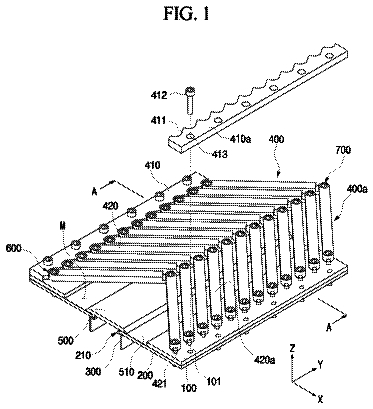
FIG. 1 is a perspective view of a guide assembly for guiding a casing in forming a sheathing wall in a ground according to one embodiment of the present invention.
FIG. 2 is a top view of a guide assembly for guiding a casing in forming a sheathing wall in a ground according to one embodiment of the present invention.
FIG. 3A is a perspective view showing a state where neighboring first and second guide-bodies are connected to each other according to one embodiment of the present invention.
FIG. 3B is a top view showing a state where neighboring first and second guide-bodies are connected to each other according to one embodiment of the present invention.
FIG. 3C is a cross-sectional view showing a state where neighboring first and second guide-bodies are connected to each other according to one embodiment of the present invention.
FIG. 4 is an enlarged view of first and second coupling units according to one embodiment of the present invention.
FIG. 5 is an exploded view of a first coupling unit according to one embodiment of the present invention.
FIG. 6A is a cross-sectional view taken along a line A-A of FIG. 2 .
FIG. 6B is a view schematically showing an example using a anchoring-bar guide channel shown in FIG. 6A .
FIG. 7 is a cross-sectional view taken along a line B-B of FIG. 2 .
FIG. 8A is a cross-sectional view taken along a line C-C of FIG. 2 .
FIG. 8B is a cross-sectional view taken along a line D-D of FIG. 2 .
FIG. 9 is a schematic illustration of a second coupling unit according to an embodiment of the present invention.
FIG. 10 is a perspective view of the second coupling unit of FIG. 9 .
FIG. 11 is a view illustrating an engaged state of the second coupling unit of FIG. 9 .
FIG. 12 is a view illustrating an unengaged state of the second coupling unit of FIG. 9 .
FIG. 13 is a schematic view illustrating a guide assembly for guiding a casing in forming a sheathing wall in a ground according to one embodiment of the present invention.
FIG. 14 is a top view of a guide assembly for guiding a casing used in forming a sheathing wall in a ground, wherein the guide assembly extends at an angle of 90 degrees, according to one embodiment of the present invention.
FIG. 15 is a view schematically showing a top face of the assembly in FIG. 14 .
FIG. 16 is a sectional view of the assembly in FIG. 14 .
FIG. 17 is a perspective view of the assembly in FIG. 14 .
FIG. 18A is a schematic view of a casing guide assembly according to one embodiment of the present invention.
FIG. 18B is a view schematically showing a front face of the assembly in FIG. 18A .
FIG. 19A is a schematic view of the casing guide assembly according to one embodiment of the present invention.
FIG. 19B is a view schematically showing a front face of the assembly in FIG. 19A .
FIG. 20A is a schematic view of a casing guide assembly according to one embodiment of the present invention.
FIG. 20B is a view schematically showing a front face of the assembly in FIG. 20A .
FIG. 21A is a schematic view of a casing guide assembly according to one embodiment of the present invention.
FIG. 21B is a view schematically showing a front face of the assembly in FIG. 21A .
FIG. 22A is a schematic view of a casing guide assembly according to one embodiment of the present invention.
FIG. 22B is a view schematically showing a front face of the assembly in FIG. 22A .
FIG. 23A is a schematic view of a casing guide assembly according to one embodiment of the present invention.
FIG. 23B is a view schematically showing a front face of the assembly in FIG. 23A .
FIG. 24 is a schematic illustration of a second coupling unit according to one embodiment of the present invention.
FIG. 25 is a sectional view taken along a line E-E in FIG. 14 .
FIG. 26 is a flowchart illustrating a method for forming a sheathing wall in a ground using the guide assembly according to one of the present invention.
For simplicity and clarity of illustration, elements in the figures are not necessarily drawn to scale. The same reference numbers in different figures denote the same or similar elements, and as such perform similar functionality.
Detailed descriptions
Examples of various embodiments are illustrated and described further below. It will be understood that the description herein is not intended to limit the claims to the specific embodiments described. On the contrary, it is intended to cover plate alternatives, modifications, and equivalents as may be included within the spirit and scope of the present disclosure as defined by the appended claims.
It will be understood that, although the terms “first”, “second”, “third”, and so on may be used herein to describe various elements, components, regions, layers and/or sections, these elements, components, regions, layers and/or sections should not be limited by these terms. These terms are used to distinguish one element, component, region, layer or section from another element, component, region, layer or section. Thus, a first element, component, region, layer or section described below could be termed a second element, component, region, layer or section, without departing from the spirit and scope of the present disclosure.
It will be understood that when an element or layer is referred to as being “connected to”, or “coupled to” another element or layer, it can be directly on, connected to, or coupled to the other element or layer, or one or more intervening elements or layers may be present. In addition, it will also be understood that when an element or layer is referred to as being “between” two elements or layers, it can be the only element or layer between the two elements or layers, or one or more intervening elements or layers may also be present.
Spatially relative terms, such as “beneath,” “below,” “lower,” “under,” “above,” “upper,” and the like, may be used herein for ease of explanation to describe one element or feature's relationship to another element s or feature s as illustrated in the figures. It will be understood that the spatially relative terms are intended to encompass different orientations of the device in use or in operation, in addition to the orientation depicted in the figures. For example, if the device in the figures is turned over, elements described as “below” or “beneath” or “under” other elements or features would then be oriented “above” the other elements or features. Thus, the example terms “below” and “under” can encompass both an orientation of above and below. The device may be otherwise oriented for example, rotated 90 degrees or at other orientations, and the spatially relative descriptors used herein should be interpreted accordingly.
The terminology used herein is for the purpose of describing particular embodiments only and is not intended to be limiting of the present disclosure. As used herein, the singular forms “a” and “an” are intended to include the plural forms as well, unless the context clearly indicates otherwise. It will be further understood that the terms “comprises”, “comprising”, “includes”, and “including” when used in this specification, specify the presence of the stated features, integers, operations, elements, and/or components, but do not preclude the presence or addition of one or more other features, integers, operations, elements, components, and/or portions thereof. As used herein, the term “and/or” includes any and all combinations of one or more of the associated listed items. Expression such as “at least one of” when preceding a list of elements may modify the entire list of elements and may not modify the individual elements of the list.
Unless otherwise defined, all terms including technical and scientific terms used herein have the same meaning as commonly understood by one of ordinary skill in the art to which this inventive concept belongs. It will be further understood that terms, such as those defined in commonly used dictionaries, should be interpreted as having a meaning that is consistent with their meaning in the context of the relevant art and will not be interpreted in an idealized or overly formal sense unless expressly so defined herein.
In the following description, numerous specific details are set forth in order to provide a thorough understanding of the present disclosure. The present disclosure may be practiced without some or all of these specific details. In other instances, well-known process structures and/or processes have not been described in detail in order not to unnecessarily obscure the present disclosure.
FIG. 1 is a perspective view of a guide assembly for guiding a casing in forming a sheathing wall in a ground according to an embodiment of the present invention. FIG. 2 is a top view of the guide assembly of FIG. 1 . FIG. 3A is a perspective view showing a state where neighboring first and second guide-bodies are connected to each other according to an embodiment of the present invention. FIG. 3B is a top view showing a state where neighboring first and second guide-bodies are connected to each other according to an embodiment of the present invention. FIG. 3C is a cross-sectional view showing a state where neighboring first and second guide-bodies are connected to each other according to an embodiment of the present invention. FIG. 4 is an enlarged view of first and second coupling units according to an embodiment of the present invention. FIG. 5 is an exploded view of a first coupling unit according to an embodiment of the present invention.
The description continues in the full USPTO document.
 Lapsed, fee not paid9 drawings