BACKGROUND OF THE INVENTION Field of the Invention
The present invention relates to an image forming apparatus and, particularly, to an image forming device that forms an image on a film-shaped medium by using an ink ribbon. Description of the Related Art
There is widely known an image forming apparatus that forms on an image on a film-shaped transfer medium. For example, such an image forming apparatus adopts an indirect printing system that forms an image (mirror image) on a transfer medium using an ink ribbon and then transfers the image formed on the transfer medium onto a surface of a printing medium such as a card or a disk.
In such an apparatus, in an image forming section thereof, a heating element constituting a thermal head is used to heat an ink ribbon and a transfer medium conveyed while being nipped between a platen roller and the thermal head from the ink ribbon side according to printing data, and thereby an image is formed on the transfer medium. Nowadays, during the image forming process, color printing in which images of a plurality of colors are overlapped with one another is widely carried out.
It is often the case in such an apparatus that a transfer medium is housed in a cassette provided with a feeding spool for feeding an unused part of an image formation region (image formation region before image formation) and a winding spool for winding an used part of the image formation region (image formation region after image formation) and, similarly, an ink ribbon in which ink panels of a plurality of colors are repeated in a face sequential manner is often housed in a cassette.
Generally, the transfer medium and ink ribbon are conveyed while laid over the upstream and downstream sides of an image forming section, and the conveying distance thereof is comparatively long. In view of this, there are provided motors for driving the feeding and winding spools, and a predetermined tension is applied to the transfer medium and ink ribbon in order to ensure their conveyance accuracy.
As disclosed in Patent Document 1 and Patent Document 2, the outer diameters of the transfer medium and ink ribbon wound around the feeding and winding spools vary every time an image is formed on the transfer medium in the image forming section, so that a drive amount (duty ratio) for motor driving is controlled in these motors. PRIOR ART DOCUMENT Patent Document
[Patent Document 1] Japanese Patent Application Publication No. 2015-13468 (see paragraphs
and [0060])
[Patent Document 2] Japanese Patent Application Publication No. 2012-162069 (see paragraphs
and [0054])
However, when rotational unevenness occurs in a drive source (motor) that drives the spool of the transfer medium or ink ribbon, its influence is reflected on the image forming process, which may result in appearance of uneven gradation irrelevant to printing data in an image formed on the transfer medium. This uneven gradation is also called “pitch unevenness”. The lower the rotation speed of the drive source, the more likely the influence of the rotational unevenness on the image formation region of the transfer medium appears, and the more noticeable the pitch unevenness becomes. The rotation speed of the drive source becomes low when the outer diameter of the transfer medium or ink ribbon wound around the spool is large (the roll diameter of the transfer medium or ink ribbon wound around the spool is large). Further, the higher a back tension applied to the transfer medium or ink ribbon is, the more likely the rotational unevenness appears as the pitch unevenness.
The pitch unevenness is eliminated when the motor drive amount is corrected (for example, the motor duty ratio is increased) to reduce the back tension on the transfer medium side; however, when the back tension is excessively reduced, the transfer medium may be pulled to the ink ribbon winding side by the drive force of a motor disposed on the ink ribbon winding side to excessively advance since the transfer medium and ink ribbon are conveyed at the same speed and in the same direction at image formation. This issue may arise not only on the transfer medium side, but also on the ink ribbon side.
Summary of the invention
The present invention has been made in view of the above problems, and the object thereof is to provide an image forming apparatus capable of forming a high quality image on a medium.
To solve the above problem, according to the present invention, the present invention provides an image forming device comprising: an image forming unit that forms an image on a film-shaped medium using an ink ribbon; a first conveying unit that has a drive source and conveys the medium while applying a tension thereto; a second conveying unit that has a drive source and conveys the ink ribbon while applying a tension thereto; and a controller that controls the image forming unit, first conveying unit, and second conveying unit, wherein one of the drive source of the first and second conveying units is a first drive source and the other drive source is a second drive source, and when the controller adjusts a drive amount of the first drive source, the controller also adjusts a drive amount of the second drive source thereof according to the adjustment amount of the first drive source.
The image forming device according to the present invention further may include: a first detection unit that detects a rotation speed of the drive source of the first conveying unit; and a second detection unit that detects a rotation speed of the drive source of the second conveying unit, and when a smaller one of the rotation speeds of the drive sources detected by the first and second detection units is lower than a prescribed reference rotation speed, the controller may adjust the drive amount of the drive source having the smaller rotation speed as the first drive source.
The controller may perform adjustment such that the absolute value of the adjustment amount of the first drive source is equal to the absolute value of the adjustment amount of the second drive source and that the respective absolute values of the adjustment amounts are positively/negatively inverted. Further, the controller may adjust the drive amount of the first drive source in such a way that a back tension to be applied to the medium or ink ribbon is reduced.
The first and second conveying units may each have an upstream-side drive source and a downstream-side drive source respectively disposed upstream and downstream of the image forming unit, and when a smaller one of the rotation speeds of the upstream-side drive sources of the respective first and second conveying units is lower than a prescribed reference rotation speed, the controller may adjust the drive amount of the upstream-side drive source having the smaller rotation speed as the first drive source and adjust the drive amount of the other upstream-side drive source according to the adjustment amount of the first drive source as the second drive source.
In the above configuration, the upstream-side drive source and downstream-side drive source each preferably drive a winding spool or a feeding spool for the medium and ink ribbon, and the winding spool and feeding spool for the medium and ink ribbon are preferably disposed opposite to each other on the upstream and downstream sides of the image forming unit. Further, the image forming device according to the present invention may further include encoders that respectively detect rotation amounts of the upstream-side and downstream-side drive sources or the winding and feeding spools, and the controller may refer to an output of the encoder while the medium and ink ribbon are conveyed by a certain amount by the first and second conveying units to detect the drive amounts of the respective upstream-side and downstream-side drive sources.
The upstream-side and downstream-side drive sources may each be a PWM controlled DC motor, and the controller may change a duty ratio of the DC motor in PWM control to adjust the drive amounts of the first and the second upstream-side drive sources. In this case, the controller may increase the duty ratio of the first upstream-side drive source and reduces the second upstream-side drive source by an increase in the duty ratio of the first upstream-side drive source.
According to the present invention, when adjusting a drive amount of the drive source of one of the first and second conveying units, the controller also adjusts a drive amount of the drive source of the other one thereof according to the adjustment amount of the drive source of the one conveying unit, thereby making it possible to prevent the film-shaped medium and ink ribbon from excessively advancing at image formation by the image forming unit, whereby a high quality image can be formed on the film-shaped medium.
Brief description of the drawings
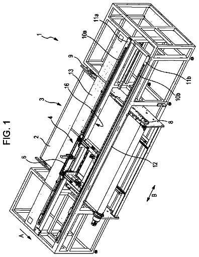
FIG. 1 is an outer appearance view of a printing system including a printer according to an embodiment of the present invention;
FIG. 2 is a front view schematically illustrating the configuration of the printer according to the embodiment;
FIG. 3 is a view for explaining a control state using cams at a waiting position where pinch rollers and a film conveying roller are separated from each other, and a platen roller and a thermal head are separated from each other;
FIG. 4 is a view for explaining a control state using the cams at a printing position where the pinch rollers and film conveying roller are brought into contact with each other, and the platen roller and thermal head are brought into contact with each other;
FIG. 5 is a view for explaining a control state using the cams at a conveying position where the pinch rollers and film conveying roller are brought into contact with each other, and the platen roller and thermal head are brought into contact with each other;
FIG. 6 is an operation explanatory view for explaining a state of the printer at the waiting position;
FIG. 7 is an operation explanatory view for explaining a state of the printer at the conveying position;
FIG. 8 is an operation explanatory view for explaining a state of the printer at the printing position;
FIG. 9 is an outer appearance view illustrating the configuration of a first unit in which the film conveying roller, platen roller, and their peripheral components are integrated for installation to the printer;
FIG. 10 is an outer appearance view illustrating the configuration of a second unit in which the pinch rollers and their peripheral components are integrated for installation to the printer;
FIG. 11 is an outer appearance view illustrating the configuration of a third unit in which the thermal head is integrated for installation to the printer;
FIGS. 12A and 12B are explanatory views each schematically explaining an image formation start position in an image formation region on a transfer film, in which FIG. 12A illustrates an image formation start position when an upstream-side mark in the printing direction is used, and FIG. 12B illustrates an image formation start position when a downstream-side mark in the printing direction is used;
FIG. 13 is a front view of the printer according to the embodiment at secondary transfer;
FIG. 14 is an explanatory view schematically illustrating the relationship between the transfer film and a card at secondary transfer;
FIG. 15 is a block diagram schematically illustrating the configuration of a control section of the printer according to the embodiment;
FIGS. 16A to 16C are explanatory views each illustrating a use state of the transfer film and ink ribbon, in which FIG. 16A illustrates a case where both of the transfer film and ink ribbon are in a brand-new state, FIG. 16B a case where the both are in an intermediate state, and FIG. 16C a case where the both are in an empty state;
FIGS. 17A to 17C are explanatory views each schematically illustrating the relationship between a conveying speed of the transfer film and a back tension, in which FIG. 17A illustrates a case where a motor rotation speed is high, FIG. 17B a case where the motor rotation speed is low while the back tension is high, and FIG. 17C a case where the back tension is reduced;
FIG. 18 is an explanatory view schematically illustrating the relationship among a back tension, a motor speed (rotation speed), and a printing result;
FIGS. 19A and 19B are explanatory views each schematically illustrating the relationship among an object to be conveyed, a sensor output, and an encoder output, in which FIG. 19A illustrates the relationship among the transfer film, an output of a sensor for detecting the position of the transfer film, and an output of an encoder of the motor driving the winding spool for the transfer film, and FIG. 19B illustrates the relationship among the ink ribbon, an output of a sensor for detecting the position of the ink ribbon, and an output of an encoder of the motor driving the feeding spool for the ink ribbon;
FIGS. 20A to 20C are timing charts each schematically illustrating duty ratios of the motor driving the feeding spool for the ink ribbon and the motor driving the winding spool for the transfer film, in which FIG. 20A illustrates a case where the duty ratios of the former and the latter are adjusted from 40% and 60% to 42% and 58%, respectively, FIG. 20B illustrates a case where the duty ratios of the former and the latter are both adjusted to 50%, and FIG. 20C illustrates a case where the duty ratios of the former and the latter are adjusted from 60% and 40% to 58% and 42%, respectively; and
FIG. 21 is a flowchart of a card issuance routine executed by a CPU of a microcomputer unit provided in a control section of the printer according to the embodiment.
Description of the preferred embodiments
Hereinafter, an embodiment in which the present invention is applied to a printer that prints and records text or images on a card while performing magnetic or electric information recording on the card will be described. 1. Configuration 1-1. System Configuration
As illustrated in FIGS. 1 and 15 , a printer 1 according to the present embodiment constitutes a part of a printing system 200 . That is, the printing system 200 roughly includes a host device 201 (for example, host computer such as a personal computer) and the printer 1 .
The printer 1 is connected to the host device 201 through an unillustrated interface, and thus an operator can instruct the printer 1 to perform recording operation or the like by transmitting printing data or magnetic or electric recording data to the printer 1 through the host device 201 . The printer 1 has an operation panel section (operation display section) 5 (see FIG. 15 ), and thus an operator can instruct the recording operation not only through the host device 201 , but also through the operation panel section 5 .
The host device 201 is connected with an image input device 204 such as a digital camera or scanner, an input device 203 such as a keyboard or a mouse to input a command and data to the host device 201 , and a monitor 202 such as a liquid crystal display to display data generated in the host device 201 . 1-2. Printer 1-2-1. Mechanism Section
As illustrated in FIG. 2 , the printer 1 has a housing 2 and includes therein an information recording section A, a printing section B, a medium storage section C, a storage section D, and a rotary unit F.
Information Recording Section A
The information recording section A includes a magnetic recording section 24 , a non-contact type IC recording section 23 , and a contact type IC recording section 27 .
Medium Storage Section C
The medium storage section C stores a plurality of cards Ca in an aligned state in a standing posture and has a separation opening 7 at the front end thereof. Through the separation opening 7 , the cards Ca are sequentially fed by a pickup roller 19 starting from a card Ca in the first row. In the present embodiment, the card Ca has a standard size (85.6 mm wide and 53.9 mm tall).
Rotary Unit F
The fed blank card Ca is sent to the rotary unit F by a carry-in roller 22 . The rotary unit F includes a rotating frame 80 axially rotatably supported by the housing 2 and two roller pairs 20 and 21 supported by the rotating frame 80 . The roller pairs 20 and 21 are axially rotatably supported by the rotating frame 80 .
Around the outer periphery of the rotary unit F, there are disposed the above-mentioned magnetic recording section 24 , non-contact type IC recording section 23 , and contact type IC recording section 27 . The roller pairs 20 and 21 form a medium conveying path 65 for conveying the card Ca to one of the information recording sections 23 , 24 , and 27 , where data is magnetically or electrically written on the card Ca. In the vicinity of the rotary unit F, there is disposed a temperature sensor Th such as a thermistor that detects ambient temperature (external temperature). Based on the ambient temperature detected by the temperature sensor Th, temperatures of heating elements such as a thermal head (to be described later) and a heat roller (to be described later) provided in the printing section B are corrected.
Printing Section
The printing section B forms an image such as a face photograph and text data on the front and back sides of the card Ca and is provided with a medium conveying path P 1 for conveying the card Ca on the extension of the medium conveying path 65 . Further, on the medium conveying path P 1 , there are disposed conveying rollers 29 and 30 that convey the card Ca, and the rollers 29 and 30 are connected to an unillustrated conveying motor.
The printing section B has a film conveying mechanism 10 and includes an image forming section B 1 and a transfer section B 2 . The image forming section B 1 uses a thermal head 40 to overlap images of different colors of an ink ribbon 41 to form an image on an image formation region (to be described later) of a transfer film 46 conveyed by the film conveying mechanism 10 . The transfer section B 2 transfers the image formed on the transfer film 46 onto the surface of the card Ca on the medium conveying path P 1 by means of a heat roller 33 .
On the downstream side of the printing section B, there is provided a medium conveying path P 2 for conveying the printed card Ca to a storage stacker 60 . On the medium conveying path P 2 , there are disposed conveying roller pairs 37 and 38 that convey the card Ca, and the rollers 37 and 38 are connected to an unillustrated conveying motor.
A decurl mechanism 12 is disposed between the conveying roller pairs 37 and 38 . The decurl mechanism 12 presses downward the center portion of the card Ca whose both end portions are nipped by the conveying roller pairs 37 and 38 by means of a convex decurl unit 33 to nip the card Ca between the convex decurl unit 33 and a position-fixed concave decurl unit 34 , thereby correcting a curl in the card Ca generated by thermal transfer by the heat roller 33 . The decurl mechanism 12 is configured to advance and retreat in the vertical direction in FIG. 2 by a mechanism including an eccentric cam 36 .
Storage Section D
The storage section D is configured to store the cards Ca sent from the printing section B in the storage stacker 60 . The storage stacker 60 is configured to be moved downward in FIG. 2 by a lifting mechanism 61 .
Details of Printing Section
Next, the printing section B of the printer 1 described above will be further described.
(6-1) Image Forming Section B 1
The transfer film 46 has a band shape having a width slightly larger than the width of the card Ca and is formed by layering an ink reception layer that receives ink of the ink ribbon 41 , a transparent protective layer that protects the surface of the ink reception layer, a peeling layer to promote integral peeling of the ink reception layer and protective layer with heat, and a substrate (base film) in this order from above.
As illustrated in FIGS. 12A and 12B , in the transfer film 46 used in the present embodiment, marks for setting an image formation start position are formed at a regular interval so as to traverse the width direction (main scan direction of the thermal head 40 ) that crosses the printing direction (sub-scan direction of the thermal head 40 ) denoted by the arrow, and the region between the marks is defined as an image formation region R. More specifically, the image formation region R is defined by a mark Ma on the upstream side in the printing direction and a mark Mb on the downstream side. The dimension of the image formation region R in the printing direction (lateral direction in FIGS. 12A and 12B ) is set to 94 mm, and that in the width direction (vertical direction in FIGS. 12A and 12B ) is to 60 mm. The thickness (width) of each of the marks Ma and Mb is set to 4 mm. In the present embodiment, the transfer film 46 is stored in a transfer film cassette in an unused state, including 500 image formation regions R (screens).
As illustrated in FIG. 2 , the transfer film 46 is wound and fed by a feeding roll 47 and a winding roll 48 that are rotated inside the transfer film cassette by driving of motors Mr 2 and Mr 4 , respectively. In the transfer film cassette, a feeding spool 47 A is disposed in the center of the feeding roll 47 , and a winding spool 48 A is disposed in the center of the winding roll 48 . Rotation drive force of the motor Mr 2 is transferred to the feeding spool 47 A through an unillustrated gear, and rotation drive force of the motor Mr 4 is transferred to the winding spool 48 A through an unillustrated gear. Forward-backward rotatable DC motors are used for the motors Mr 2 and Mr 4 . Further, an unillustrated encoder (hereinafter, referred to as “encoder for motor Mr 2 ” and “encoder for motor Mr 4 ”) that detects the rotation speed of the motor Mr 2 or Mr 4 is provided to the motor shaft thereof at a position opposite to the output shaft side.
In the present embodiment, the transfer film 46 before undergoing transfer processing is wound around the feeding spool 47 A, and used (part already subjected to transfer processing by the transfer section B 2 ) transfer film 46 is wound around the winding spool 48 A. Thus, when image formation processing and transfer processing are applied to the transfer film 46 , the transfer film 46 is once fed from the feeding spool 47 A to the winding spool 48 A, and then image formation processing and transfer processing are performed while winding the transfer film 46 by the feeding spool 47 A.
A film conveying roller 49 is a main drive roller for carrying the transfer film 46 , and by controlling the driving of the roller 49 , the conveying amount and the conveying stop position of the transfer film 46 are determined. The film conveying roller 49 is connected to a forward-backward rotatable film conveying motor Mr 5 (stepping motor). Although the motors Mr 2 and Mr 4 are also driven when the film conveying roller 49 is driven, they are configured to wind the transfer film 46 fed from one of the feeding roll 47 and winding roll 48 by the other one to apply a tension to the conveyed transfer film 46 . That is, the motors Mr 2 and Mr 4 perform an auxiliary function for film conveyance and are not driven as a main conveying source for the transfer film 46 .
Pinch rollers 32 a and 32 b are disposed on the periphery of the film conveying roller 49 . Although not illustrated in FIG. 2 , the pinch rollers 32 a and 32 b are configured to advance and retreat with respect to the film conveying roller 49 , and in the state illustrated in FIG. 2 , the rollers 32 a and 32 b advance to the film conveying roller 49 to come into pressure-contact therewith, thereby winding the transfer film 46 around the film conveying roller 49 . By this means, the transfer film 46 undergoes accurate conveyance by a distance according to the rotation speed of the film conveying roller 49 .
Thus, by driving the film conveying roller 49 as the main drive roller disposed between the image forming section B 1 and the transfer section B 2 , the film conveying mechanism 10 can convey the transfer film 46 forward and backward among the feeding roll 47 , image forming section B 1 , transfer section B 2 , and winding roll 48 and can locate the image formation region R of the transfer film 46 and an image formed in the image formation region R at an adequate position (cueing position) in the image forming section B 1 and transfer section B 2 . Further, there are disposed transmission-type sensors Se 1 and Se 3 between the winding roll 48 and the image forming section B 1 (thermal head 40 and platen roller 45 ) and between the film conveying roller 49 and the transfer section B 2 (heat roller 33 and platen roller 31 ), respectively. The sensors Se 1 and Se 3 each have a light-emitting element and a light-receiving element and detect the above-mentioned mark formed on the transfer film 46 .
Hereinafter, the relationship between the marks Ma and Mb formed on the transfer film 46 and the image formation start position (printing start position of the thermal head 40 ) in the image formation region R on the transfer film 46 will be described.
(A) Case where Mark Ma is Used for Cueing
FIG. 12A schematically illustrates the image formation start position set with respect to the image formation region R on the transfer film 46 in the image forming section B 1 in a case where the mark Ma on the upstream side relative to the image formation region R in the printing direction is used for cueing (when the mark Ma is detected by the sensor Se 1 ). As illustrated in FIG. 12A , in the present embodiment, an image formation start position PA in the image formation region R when the mark Ma is used for cueing is set at a position of 90.3 mm from the front end of the mark Ma in the printing direction. In other words, the center of the length of the image formation region R in the printing direction and the center of the length of a region printable by the thermal head 40 (hereinafter, referred to as “printing region of the thermal head 40 ”) in the printing direction are made to coincide with each other.
In FIG. 12A , the continuous line rectangular area within the image formation region R corresponds to the printing region of the thermal head 40 , and the area denoted by the dashed double-dotted line corresponds to the card Ca. In the present embodiment, the printing region of the thermal head 40 is set to 86. 6 mm wide and 54.9 mm tall so as to have a margin of about 0.5 mm on the up, down, left, and right sides of the card Ca of standard size. In other words, the distance between the front end of the mark Ma and the printing region (image formation end position) of the thermal head 40 and the distance between the rear end of the mark Mb and the image formation start position PA are each 3.7 mm.
(B) Case where Mark Mb is Used for Cueing
FIG. 12B schematically illustrates the image formation start position set with respect to the image formation region R on the transfer film 46 in the image forming section B 1 in a case where the mark Mb on the downstream side relative to the image formation region R in the printing direction is used for cueing. As illustrated in FIG. 12B , an image formation start position PB in the image formation region R when the mark Mb is used for cueing is set at a position of 7.7 mm from the front end of the mark Mb in the printing direction. In other words, the center of the length of the image formation region R in the printing direction and the center of the length of the printing region of the thermal head 40 in the printing direction are made to coincide with each other.
Referring back to FIG. 2 , the ink ribbon 41 is stored in an ink ribbon cassette 42 in a state being stretched between a feeding roll 43 for feeding the ink ribbon 41 to the ink ribbon cassette 42 and a winding roll 44 for winding the ink ribbon 41 . A winding spool 44 A is disposed in the center of the winding roll 44 , and a feeding spool 43 A is disposed in the center of the feeding roll 43 . The winding spool 44 A is rotated by drive force of a motor Mr 1 , and the feeding spool 43 A is rotated by drive force of a motor Mr 3 .
Forward-backward rotatable DC motors are used for the motors Mr 1 and Mr 3 . Like the above-described motors Mr 2 and Mr 4 , an unillustrated encoder (hereinafter, referred to as “encoder for motor Mr 1 ” and “encoder for motor Mr 3 ”) that detects the rotation speed of the motor Mr 1 or Mr 3 is provided to the motor shaft thereof at a position opposite to the output shaft side. The motors Mr 1 and Mr 3 constitute an ink ribbon conveying section 11 (see FIG. 2 ) that conveys the ink ribbon 41 . In the present embodiment, the feeding and winding spools 47 A and 48 A for the transfer film 46 and the feeding and winding spools 43 A and 44 A for the ink ribbon 41 are disposed opposite to each other on the upstream and downstream sides of the image forming section B 1 (thermal head 40 and platen roller 45 ).
The ink ribbon 41 is configured by repeating color ink panels of Y (Yellow), M (Magenta), and C (Cyan) and a Bk (Black) ink panel in the longitudinal direction in a face sequential manner. In the present embodiment, sublimation ink is used for the color ink panels of Y, M, and C, and molten ink is used for the Bk ink panel. However, the sublimation ink may be used for the Bk ink panel. Further, a transmission type sensor Se 2 is disposed between the feeding roll 43 and the image forming section B 1 (thermal head 40 and platen roller 45 ). The transmission type sensor Se 2 detects the position of the ink ribbon 41 by detecting a state where light from the light-emitting element is shielded on the light receiving element side by the Bk ink panel so as to perform the cueing of the ink ribbon 41 to be fed to the image forming section B 1 . In the present embodiment, the ink ribbon 41 is stored in the ink ribbon cassette 42 in an unused state, including ink panels of Y, M, C, and Bk corresponding to 500 screens which are repeated in a face sequential manner so as to correspond to the image formation regions R of the transfer film 46 .
The platen roller 45 and thermal head 40 constitute the image forming section B 1 , and the thermal head 40 is disposed opposed to the platen roller 45 . At image formation, the platen roller 45 is brought into pressure-contact with the thermal head 40 with the transfer film 46 and the ink ribbon 41 interposed therebetween. The thermal head 40 has a plurality of heating elements lined in the main scan direction. These heating elements are selectively heated under the control of a head control IC (not illustrated) according to printing data and form an image on the transfer film 46 through the ink ribbon 41 . At this time, the transfer film 46 and ink ribbon 41 are conveyed at the same speed and in the same direction (printing direction illustrated in FIGS. 12A and 12B , i.e., upward direction in FIG. 2 ). The thermal head 40 is cooled by a cooling fan 39 .
The ink ribbon 41 with which printing on the transfer film 46 is finished is peeled off from the transfer film 46 by means of a peeling roller 25 and a peeling member 28 . The peeling member 28 is fixed to the ink ribbon cassette 42 , the peeling roller 25 comes into contact with the peeling member 28 at image formation, and the roller 25 and peeling member 28 nip the transfer film 46 and ink ribbon 41 to perform peeling. The peeled ink ribbon 41 is wound around the winding roll 44 by drive force of the motor Mr 1 , and the transfer film 46 is conveyed to the transfer section B 2 having the platen roller 31 and heat roller 33 by the film conveying roller 49 .
(6-2) Transfer Section B 2
In the transfer section B 2 , the transfer film 46 is nipped together with the card Ca by the heat roller 33 and platen roller 31 , and an image formed in the image formation region R on the transfer film 46 is transferred to the surface of the card Ca. That is, at image transfer, the heat roller 33 is brought into pressure-contact with the platen roller 31 with the card Ca and transfer film 46 (image formation region R thereon) interposed therebetween, and the card Ca and transfer film 46 are conveyed at the same speed and in the same direction (see also FIG. 13 ). The heat roller 33 is mounted to a lifting mechanism (not illustrated) so as to come into pressure contact with and separate from the platen roller 31 through the transfer film 46 .
FIG. 13 is a front view of the printer 1 in a state where secondary transfer processing is performed in the transfer section B 2 . At the secondary transfer processing, the mark Mb is detected by the sensor Se 3 for cueing irrespective of whether the mark Ma or mark Mb is used for cueing. In the present embodiment, a position where the transfer film 46 is further conveyed by the film conveying motor Mr 5 by 30 mm from the position where the sensor Se 3 detects the front end of the mark Mb is set as a (secondary) transfer start position.
FIG. 14 schematically illustrates alignment between the image formation region R and the card Ca. As illustrated in FIG. 14 , in the secondary transfer processing, the transfer film 46 is cued in such a way that the center Cn of the length of the printing region of the thermal head 40 in the printing direction and the center of the card Ca in the longitudinal direction thereof are made to coincide with each other. This is achieved by further conveying the transfer film 46 by 30 mm from the position where the sensor Se 3 detects the front end of the mark Mb.
The transfer film 46 after image transfer is separated (peeled off) from the card Ca by means of a peeling pin 79 disposed between the heat roller 33 and a driven roller 37 b constituting the conveying roller pair 37 and conveyed to the feeding roll 47 side. On the other hand, the card Ca to which the image is transferred is conveyed downstream on the medium conveying path P 2 toward the decurl mechanism 12 .
(6-3) Details of Image Forming Section B 1
Details of the configuration of the image forming section B 1 will be described. As illustrated in FIGS. 3 to 5 , the pinch rollers 32 a and 32 b are supported respectively by an upper end portion and a lower end portion of a pinch roller support member 57 , and the pinch roller support member 57 is rotatably supported by a support shaft 58 penetrating the center portion of the member 57 . As illustrated in FIG. 10 , the support shaft 58 is laid at its opposite end portions between long holes 76 and 77 formed in the pinch roller support member 57 and is fixed at its center portion to a fixing part 78 of a bracket 50 . Further, the long holes 76 and 77 are provided with spaces in the horizontal direction and vertical direction with respect to the support shaft 58 . This allows adjustment of the positions of the pinch rollers 32 a and 32 b with respect to the film conveying roller 49 , the details of which will be described later.
Spring members 51 ( 51 a , 51 b ) are mounted on the support shaft 58 , and end portions of the pinch roller support member 57 on which the pinch rollers 32 a and 32 b are installed each contact the spring members 51 and are biased to the direction of the film conveying roller 49 by the spring force of the spring members 51 .
The bracket 50 comes into contact with the cam operation surface of a cam 53 at a cam receiver 81 and is configured to be moved in the horizontal direction with respect to the film conveying roller 49 in the figure in accordance with rotation of the cam 53 in the arrow direction with a cam shaft 82 rotated by drive force of a drive motor 54 (see FIG. 10 ) as a rotation axis. Accordingly, when the bracket 50 advances toward the film conveying roller 49 ( FIGS. 4 and 5 ), the pinch rollers 32 a and 32 b come into pressure-contact with the film conveying roller 49 against the biasing force of the spring members 51 with the transfer film 46 nipped therebetween and wind the transfer film 46 around the film conveying roller 49 .
At this point, the pinch roller 32 b in a farther position from a shaft 95 as a rotation axis of the bracket 50 first comes into pressure-contact with the film conveying roller 49 , and then, the pinch roller 32 a comes into pressure-contact with the same. In this way, by arranging the shaft 95 that is the rotation axis above the film conveying roller 49 , the pinch roller support member 57 comes into contact with the film conveying roller 49 while being rotated, instead of parallel shift, which advantageously reduces a space in the width direction as compared with a case where the pinch roller support member 57 is parallelly shifted.
Further, the pressure-contact force when the pinch rollers 32 a and 32 b come into pressure-contact with the film conveying roller 49 is uniform in the width direction of the transfer film 46 by the spring members 51 . At this point, the long holes 76 and 77 are formed on both sides of the pinch roller support member 57 , and the support shaft 58 is fixed to the fixing part 78 , so that it is possible to adjust the pinch roller support member 57 in three directions, and the transfer film 46 is conveyed in a correct posture by rotation of the film conveying roller 49 without causing skew. The adjustments in three directions mentioned herein include (i) adjusting the degree of parallelization of the shafts of the pinch rollers 32 a and 32 b with respect to the shaft of the film conveying roller 49 in the horizontal direction to uniform the pressure-contact force of the pinch rollers 32 a and 32 b in the shaft direction with respect to the film conveying roller 49 , (ii) adjusting the moving distances of the pinch rollers 32 a and 32 b with respect to the film conveying roller 49 to uniform the pressure-contact force of the pinch roller 32 a against the film conveying roller 49 and the pressure-contact force of the pinch roller 32 b against the film conveying roller 49 , and (iii) adjusting the degree of parallelization of the shafts of the pinch rollers 32 a and 32 b in the vertical direction with respect to the shaft of the film conveying roller 49 so that the shafts of the pinch rollers 32 a and 32 b are perpendicular to the film travel direction.
Further, the bracket 50 is provided with a tension receiving member 52 that comes into contact with a part of the transfer film 46 that is not wound around the film conveying roller 49 when the bracket 50 advances toward the film conveying roller 49 .
The tension receiving member 52 is provided to prevent the pinch rollers 32 a and 32 b from retracting from the film conveying roller 49 against the biasing force of the spring members 51 due to the tension of the transfer film 46 caused when the pinch rollers 32 a and 32 b bring the transfer film 46 into pressure-contact with the film conveying roller 49 . Accordingly, the tension receiving member 52 is attached to the front end of the rotation side end portion of the bracket 50 so as to come into contact with the transfer film 46 at the position to the left of the pinch rollers 32 a and 32 b in the figure. FIG. 2 illustrates a state where the tension receiving member 52 is brought into contact with the transfer film 46 .
As a result, the cam 53 is capable of directly receiving the tension caused due to elasticity of the transfer film 46 through the tension receiving member 52 . This prevents the pinch rollers 32 a and 32 b from retracting from the film conveying roller 49 due to the tension to prevent the pressure-contact force of the pinch rollers 32 a and 32 b from decreasing, thereby maintaining the winding state in which the transfer film 46 is brought into intimate contact with the film conveying roller 49 , which allows accurate conveyance to be performed.
The description continues in the full USPTO document.
 Lapsed, fee not paid5 drawings