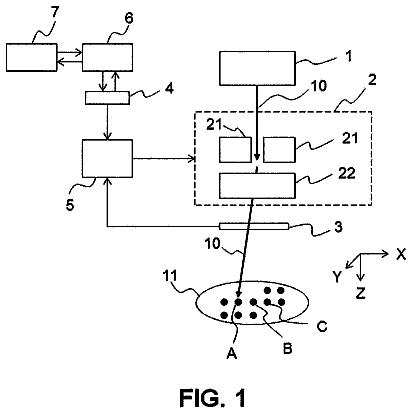
The disclosed embodiments generally relate to improvements in ion beam generation, including proton beam generation, and particularly to ion beam generation via interactions between an electromagnetic radiation beam and an ion-generating target.
Background
Aspects of this disclosure include many systems, subsystems, components and subcomponents. Background details already known are not repeated herein. Such background information may include information contained in the following materials: U.S. Pat. No. 8,229,075 to Cowan et al., titled “Targets and Processes for Fabricating Same,” issued Jul. 24, 2012; U.S. Pat. No. 8,389,954 to Zigler et al., titled “System for Fast Ions Generation and a Method Thereof,” issued Mar. 5, 2013; U.S. Pat. No. 8,530,852 to Le Galloudec, titled “Micro-Cone Targets for Producing High Energy and Low Divergence Particle Beams,” issued Sep. 10, 2013; U.S. Pat. No. 8,750,459 to Cowan et al., titled “Targets and Processes for Fabricating Same,” issued Jun. 10, 2014; U.S. Pat. No. 9,236,215 to Zigler et al., titled “System for Fast Ions Generation and a Method Thereof,” issued Jan. 12, 2016; U.S. Pat. No. 9,345,119 to Adams et al., titled “Targets and Processes for Fabricating Same,” issued May 17, 2016; and U.S. Pat. No. 9,530,605 to Nahum et al., titled “Laser Activated Magnetic Field Manipulation of Laser Driven Ion Beams,” issued Dec. 27, 2016.
Particle radio-therapy conducted with ions may be used to treat disease. In one form of particle therapy, called proton therapy, a tumor is treated by irradiating it with protons (e.g., hydrogen ions). Proton therapy has advantages over conventional photon-based therapies (e.g., x-ray and gamma ray therapies) in part due to the way protons and photons interact with a patient's tissue.
FIG. 1 shows the radiation dose as a function of tissue depth for both photon and proton therapies. Before a particle can irradiate the treatment volume 106 defined by the patient's treatment plan, it typically must traverse the patient's skin and other healthy tissue before reaching the treatment volume 106 of the patient. In doing so, the particles can damage healthy tissue, an undesirable side-effect of the treatment. As shown in curve 102 of FIG. 1 , photons (e.g., x-rays) deliver most of their energy to the regions near the patient's skin. For tumors deeper in the patient's body, this interaction may damage healthy tissue. Additionally, some photons traverse the patient's body beyond the treatment volume 106 , irradiating yet more healthy tissue behind the tumor before ultimately exiting the other side of the patient's body. Although the radiation doses to these other healthy tissues is lower than the dose delivered near the patient's skin, it is still undesirable.
Unlike photons, protons, exhibit a very desirable interaction with the patient's tissue. As shown by curve 104 in FIG. 1 , the peak interaction of protons with the patient's tissue occurs deeper within the patient and may cease abruptly after the peak interaction. Additionally, protons interact with surface tissues much less than photons, meaning that the majority of the proton beam's energy can be delivered to the treatment volume 106 , and the irradiation of healthy tissue can be reduced. Taking advantage of these benefits, proton therapy thus allows more precise administration of energy to unhealthy tissue in patients while avoiding damage to healthy tissue. For example, proton therapy may reduce damage to surrounding healthy tissue by 2 to 6 times when compared to x-ray therapy, thereby improving patient survival and quality of life. Protons may reduce the lifetime risk of secondary cancer in children by 97%, compared to x-rays.
Commercial proton therapy centers are currently rare due to disadvantages in existing proton therapy systems, which generate proton beams by using large and costly particle accelerators. Accelerator-based systems can be massive and are not scalable. As an example, FIG. 2 shows an approximate size comparison of an accelerator-based proton therapy system against a football field. The energy requirements and maintenance costs inherent in operating an accelerator-based system are also immense. Taken together, these disadvantages lead to exorbitant construction and maintenance costs associated with proton therapy. In addition to the extravagant costs associated with accelerator-based proton beam generation, adjusting certain properties of the proton beam (e.g., the beam energy and beam flux) can be cumbersome and time-consuming in such systems. This leads to longer treatment times and low patient throughput, further increasing the cost of individual treatments as fewer patients share the cost burden. Accordingly, few proton therapy centers currently exist, and patients often receive inferior treatments due, in part, to unavailability of proton therapy.
The present disclosure is directed to alternative approaches to proton therapy. Although the embodiments disclosed herein contemplate the medical application of proton beam therapy, a person of ordinary skill in the art would understand that the novel proton beam generating methods and systems described below can be used in any application where a proton beam is desired.
Brief summary of exemplary disclosed embodiments
Some of the embodiments disclosed herein provide methods and systems for improved generation of a proton beam. For example, disclosed embodiments may improve upon disadvantages of some conventional proton generation technologies, as described above, for example by providing improved speed, precision, and configurability, allowing proton beam generation to be performed more efficiently and at a lower cost. Disclosed embodiments may further reduce the size and complexity of existing systems.
Consistent with the present embodiments, a system for generating a proton beam may include an interaction chamber configured to support an ion-generating target at a target location; an electromagnetic radiation source configured to provide an electromagnetic radiation beam along a trajectory, the electromagnetic radiation beam having an energy, a polarization, a spatial profile, and a temporal profile; one or more optics components positioned along the trajectory of the electromagnetic radiation beam between the electromagnetic radiation source and a surface of the ion-generating target, the one or more optics components being configured to cooperate with the electromagnetic radiation beam to cause the electromagnetic radiation beam to irradiate the ion-generating target, thereby facilitating formation of a proton beam having an energy and a flux; and at least one processor configured to control at least one of the electromagnetic radiation source and the one or more optics components to thereby alter at least one of the energy of the electromagnetic radiation beam, the polarization of the electromagnetic radiation beam, the spatial profile of the electromagnetic radiation beam, and the temporal profile of the electromagnetic radiation beam, in order to adjust at least one of: the flux of the proton beam while holding the energy of the proton beam substantially constant; and the energy of the proton beam while holding the flux of the proton beam substantially constant.
Some embodiments may include a method for generating a proton beam including supporting an ion-generating target at a target location within an interaction chamber; providing, by an electromagnetic radiation source, an electromagnetic radiation beam along a trajectory, the electromagnetic radiation beam having an energy, a polarization, a spatial profile, and a temporal profile; irradiating the ion-generating target with the electromagnetic radiation beam, by one or more optics components positioned along the trajectory of the electromagnetic radiation beam between the electromagnetic radiation source and a surface of the ion-generating target, the one or more optics components being configured to cooperate with the electromagnetic radiation beam to facilitate forming a proton beam having an energy and a flux; and controlling, by at least one processor, at least one of the electromagnetic radiation source and the one or more optics components to alter at least one of the energy of the electromagnetic radiation beam, the polarization of the electromagnetic radiation beam, the spatial profile of the electromagnetic radiation beam, and the temporal profile of the electromagnetic radiation beam, in order to adjust at least one of: the flux of the proton beam while holding the energy of the proton beam substantially constant; and the energy of the proton beam while holding the flux of the proton beam substantially constant.
Further, consistent with the present embodiments, a system for generating a proton beam may include an interaction chamber configured to support an ion-generating target at a target location; an electromagnetic radiation source configured to provide an electromagnetic radiation beam along a trajectory, the electromagnetic radiation beam having an energy, a polarization, a spatial profile, and a temporal profile; one or more optics components positioned along the trajectory of the electromagnetic radiation beam between the electromagnetic radiation source and a surface of the ion-generating target, the one or more optics components being configured to cooperate with the electromagnetic radiation beam to cause the electromagnetic radiation beam to irradiate the ion-generating target, thereby facilitating formation of a proton beam having an energy and a flux; and at least one processor configured to control at least one of the electromagnetic radiation source and the one or more optics components to thereby alter at least one of the energy of the electromagnetic radiation beam, the polarization of the electromagnetic radiation beam, the spatial profile of the electromagnetic radiation beam, and the temporal profile of the electromagnetic radiation beam, in order to adjust at least one of: the flux of the proton beam while varying the energy of the proton beam; and the energy of the proton beam while varying the flux of the proton beam.
Some embodiments may include a method for generating a proton beam including supporting an ion-generating target at a target location within an interaction chamber; providing, by an electromagnetic radiation source, an electromagnetic radiation beam along a trajectory, the electromagnetic radiation beam having an energy, a polarization, a spatial profile, and a temporal profile; irradiating the ion-generating target with the electromagnetic radiation beam, by one or more optics components positioned along the trajectory of the electromagnetic radiation beam between the electromagnetic radiation source and a surface of the ion-generating target, the one or more optics components being configured to cooperate with the electromagnetic radiation beam to facilitate forming a proton beam having an energy and a flux; and controlling, by at least one processor, at least one of the electromagnetic radiation source and the one or more optics components to alter at least one of the energy of the electromagnetic radiation beam, the polarization of the electromagnetic radiation beam, the spatial profile of the electromagnetic radiation beam, and the temporal profile of the electromagnetic radiation beam, in order to adjust at least one of: the flux of the proton beam while varying the energy of the proton beam; and the energy of the proton beam while varying the flux of the proton beam.
By way of example, the at least one processor may be configured to alter the spatial profile of the electromagnetic radiation beam by altering a spot size of the electromagnetic radiation beam.
Further, consistent with the present embodiments, the at least one processor may be configured to alter the temporal profile of the electromagnetic radiation beam by altering a chirp of the electromagnetic radiation beam.
Further, consistent with the present embodiments, the at least one processor may be configured to alter the temporal profile of the electromagnetic radiation beam by altering a timing of one or more pump sources.
Further, consistent with the present embodiments, the polarization of the electromagnetic radiation beam may be such that the electromagnetic radiation beam is not polarized.
Further, consistent with the present embodiments, the electromagnetic radiation source may be configured to provide a pulsed electromagnetic radiation beam and to thereby cause a pulsed proton beam.
Further, consistent with the present embodiments, the at least one processor may be configured to cause the electromagnetic radiation source to change the energy of the electromagnetic radiation beam and the temporal profile of the electromagnetic radiation beam.
Further, consistent with the present embodiments, the one or more processors may be configured to cause the electromagnetic radiation source to change the energy of the electromagnetic radiation beam and the spatial profile of the electromagnetic radiation beam.
Further, consistent with the present embodiments, the at least one processor may be configured to cause the electromagnetic radiation source to change the energy of the electromagnetic radiation beam, and the at least one processor may be configured to cause the one or more optics components to change the spatial profile of the electromagnetic radiation beam.
Further, consistent with the present embodiments, the at least one processor may be configured to cause the one or more optics components to change the energy of the electromagnetic radiation beam and the spatial profile of the electromagnetic radiation beam.
Consistent with other disclosed embodiments, non-transitory computer-readable storage media may store program instructions, which are executed by one or more processor devices and perform any of the methods described herein.
The foregoing general description is a brief summary of only a few disclosed embodiments, and is not intended to be restrictive of the numerous inventive concepts set forth in the following drawings, detailed description, and claims.
Brief description of the drawings
The accompanying drawings, which are incorporated in and constitute a part of this specification, illustrate certain aspects of the disclosed embodiments and, together with the description, explain the disclosed embodiments. In the drawings:
FIG. 1 is a graph depicting radiation dose correlated to tissue depth.
FIG. 2 is an approximate representation of size of some conventional accelerator-based particle therapy systems, as described above.
FIG. 3 is a diagram of an example of interconnected components of a system for providing proton therapy, consistent with disclosed embodiments.
FIGS. 4A, 4B, 4C, 4D, and 4E are examples of ion-generating targets for proton beam generation, consistent with disclosed embodiments.
FIG. 5 is a schematic diagram of an example of a controller for controlling a proton therapy system, consistent with disclosed embodiments.
FIG. 6 is a schematic diagram of an example of an electromagnetic radiation source, consistent with disclosed embodiments.
FIG. 7 is a schematic diagram of an example of a gantry, consistent with disclosed embodiments.
FIG. 8 is a schematic diagram of another example of a gantry, consistent with disclosed embodiments.
FIG. 9 is a flowchart of an example of a proton therapy process, consistent with disclosed embodiments.
FIG. 10 illustrates aspects of an example of an interaction chamber, consistent with disclosed embodiments.
FIG. 11 is a flowchart of an example of a process for controlling proton therapy with proton generation feedback, consistent with disclosed embodiments.
FIG. 12 depicts energy of an exemplary proton beam pulse consistent with disclosed embodiments.
FIGS. 13A and 13B depict an example of a proton energy selection system, consistent with disclosed embodiments.
FIG. 14 is a flowchart of an example of a process for controlling proton therapy treatment in a three dimensional space, based on proton generation feedback, consistent with disclosed embodiments.
FIGS. 15A, 15B, 15C, and 15D depict aspects of an exemplary proton therapy treatment based on the process of FIG. 14 .
Detailed description
Reference is now made in detail to exemplary embodiments, examples of which are illustrated in the accompanying drawings and disclosed herein. Wherever convenient, the same reference numbers are used throughout the drawings to refer to the same or like parts.
Systems and methods are provided herein for providing ion beam therapy. The following embodiments are described in relation to proton therapy. As used here, “proton therapy” refers to a particle therapy medical procedure that uses a beam of protons to irradiate diseased tissue, most often in the treatment of cancer. While this description refers to this therapeutic procedure, it is to be understood that the intended scope of the innovations herein are not limited to therapy or medical procedures. Rather, it may apply any time a proton beam is generated for any purpose. In addition, the disclosure is not limited to the generation of beams of protons, but also applies to other forms of ion beam generation.
A system for generating a proton beam in accordance with the present disclosure may comprise one or more sources of electromagnetic radiation. “Electromagnetic radiation,” as used in the present disclosure may refer to any form of electromagnetic radiation having any wavelength, frequency, energy, power, polarization, and/or spatial or temporal profile. In some embodiments, electromagnetic radiation may propagate in the form of a beam. For example, an electromagnetic radiation beam may be any form of electromagnetic radiation suitable for irradiating a desired location. In some embodiments, a system for providing proton therapy system may be configured to provide an electromagnetic radiation beam along a trajectory. An electromagnetic radiation beam may, for example, be configured for irradiating a plurality of patterned features on an ion-generating target (as described in further detail below) or for irradiating one or more knife edges on an ion-generating target (also described in further detail below).
An electromagnetic radiation beam may comprise a defined energy, wavelength, power, energy, polarization (or it may not be polarized), spatial profile, and/or temporal profile. Any of these traits may be fixed or may vary. As an example, an electromagnetic radiation source may be configured to provide a laser beam having traits tailored to properties of an ion-generating target. An electromagnetic radiation beam may be pulsed, to thereby cause a pulsed proton beam, or it may be continuous to thereby cause a continuous proton beam.
A system for generating a proton beam in accordance with the present disclosure may comprise an ion-generating target. As used in the present disclosure, an ion-generating target may refer to any material, apparatus, or combination of elements configured for generating ions in response to electromagnetic irradiation. As described below, an ion-generating target may be configured for generating a proton beam; however, a proton beam is merely an example. In some embodiments, an ion-generating target may be provided with a plurality of patterned features. For example, a plurality of patterned features may comprise protrusions extending from a surface of an ion-generating target. In some embodiments, an ion-generating target may patterned with one or more knife edges. For example, a knife edge of an ion-generating target may include one or more narrow edges, similar to an arête or the edge of a blade.
A system for generating a proton beam in accordance with the present disclosure may comprise optics component(s). As used in the present disclosure, optics component(s) may refer to any one or more components for manipulating and/or controlling an electromagnetic radiation beam in any manner, including, for example, shaping, directing, filtering, splitting, delaying, modulating, absorbing, amplifying, focusing, chopping, and/or reflecting an electromagnetic radiation beam. As an example, optics components may be positioned along a trajectory of an electromagnetic radiation beam, for example between an electromagnetic radiation source and a surface of an ion-generating target. In some embodiments, optics components may be configured to direct the electromagnetic radiation beam at the ion-generating target, for example to thereby cause a resultant proton beam. Further, an electromagnetic radiation source may include one or more optics components to facilitate formation of an electromagnetic radiation beam.
Consistent with the present disclosure, optics components may include one or more adaptive mirror(s). As used in the present disclosure, an adaptive mirror may refer to an element that includes a reflective surface that may be adapted. For example, an adaptive mirror may be a deformable mirror that comprises a plurality of facets, each of the plurality of facets being independently controllable by a digital logic circuitry. As another example, an adaptive mirror may be a plasma mirror that comprises a laser pulse focused onto an anti-reflective coated substrate, one or both of the laser pulse and anti-reflective coated substrate being controllable by a digital logic circuitry. In some embodiments, an adaptive mirror may be configured to direct an electromagnetic radiation beam at an ion-generating target or, in some instances, configured to cooperate with an electromagnetic radiation beam to cause electromagnetic radiation beam to irradiate the ion-generating target, thereby facilitating formation of a proton beam. An adaptive mirror in accordance with the present disclosure may be configured to adjust or control a spatial profile of an electromagnetic radiation beam and/or to adjust or control at least one of a relative position and orientation between an electromagnetic beam and an ion-generating target. In some instances, an adaptive mirror may be configured to direct an electromagnetic radiation beam by adjusting one or more property of the electromagnetic radiation beam. For example, adjustment may be achieved by at least one of adjusting a focus of the electromagnetic radiation beam, diverting the electromagnetic radiation beam, and scanning the electromagnetic radiation beam.
Consistent with the present disclosure, a system for generating a proton beam may be configured to raster an electromagnetic radiation beam, for example over an ion-generating target. As used in the present disclosure, rastering may refer to a pattern of sequential scanning over a surface or volume having any shape. Rastering may, for example, be achieved by one or more motor configured to cause an electromagnetic radiation beam to sequentially scan a surface or volume. In some embodiments, an electromagnetic radiation beam may be rastered over individual patterned features of an ion-generating target or a knife edge of an ion-generating target. In some embodiments, an adaptive mirror may be configured to direct an electromagnetic radiation beam to strike individual features of an ion-generating target.
A system for generating a proton beam in accordance with the present disclosure may comprise proton beam adjustment component(s). As used in the present disclosure, proton beam adjustment component(s) may refer to any one or more components for manipulating and/or controlling a proton beam in any manner, including, for example, accelerating, analyzing, directing, shaping, filtering, splitting, delaying, modulating, absorbing, amplifying, focusing, chopping, and/or reflecting a proton beam. For example, a proton beam adjustment component may include one or more quadrupole lens, cylindrical mirror lens/analyzer (“CMA”), spherical mirror lens/analyzer (“BMA”), collimator, energy degrader, time-of flight control unit, magnetic dipole, or any other component suitable for manipulating charged ions.
A system for generating a proton beam in accordance with the present disclosure may be used in conjunction with a system for treating a treatment volume with protons. In the case of a medical treatment, the volume may be a group of cells or an area of tissue. If employed outside the medical field, the volume may be any area or region for which benefit may be achieved through an application of radiation.
In accordance with the present disclosure, a gantry may be provided. A gantry may refer to any apparatus configured to assist in directing radiation toward a target. The target to be irradiated may be, for example, a treatment volume such as a tumor within a patient's body. Because a system for treating a treatment volume with protons consistent with the present disclosure is just one application of the disclosed systems for generating a proton beam, it should be understood that this is merely an example. A gantry may also be used to direct a proton beam or other radiation beam toward any target to be irradiated.
In accordance with the present disclosure, a patient support platform may be provided. A patient support platform may refer to any surface, foundation, or other structure configured to support a patient during irradiation therapy. A patient support platform may be fixed, or it may be adjustable in any dimension.
Any of the systems in accordance with the present disclosure may comprise at least one processor configured to monitor, control, and/or facilitate the use of any component included in the system. Consistent with the disclosed embodiments, a processor may refer to any one or more processing devices, including, for example, an application specific integrated circuit (ASIC), a digital signal processor (DSP), a programmable logic device (PLD), a field programmable gate array (FPGA), a controller, a microprocessor, or other similar electronic devices and/or combinations thereof. A processor may comprise one or more modules of a control system.
In some embodiments consistent with the present disclosure, at least one processor may be configured to cause an electromagnetic radiation beam to strike individual patterned features that make up a plurality of patterned features an ion-generating target, and to thereby generate a resultant proton beam. In some embodiments consistent with the present disclosure, at least one processor may be configured to cause an electromagnetic radiation beam to strike one or more knife edges of an ion-generating target, and to thereby generate a resultant proton beam.
In some embodiments, at least one processor may control at least one of an electromagnetic radiation source and/or optics components. For example, a processor or group of processors may control at least one of the energy of an electromagnetic radiation beam, the flux of an electromagnetic radiation beam, the polarization of an electromagnetic radiation beam, the spatial profile of an electromagnetic energy beam, the temporal profile of an electromagnetic radiation beam, or other aspects of an electromagnetic radiation beam. More specifically, at least one processor may generate instructions to cause an electromagnetic radiation source to alter a spatial profile of an electromagnetic radiation beam by altering a spot size of the electromagnetic radiation beam. As another example, at least one processor may alter a temporal profile of an electromagnetic radiation beam by altering a chirp of the electromagnetic radiation beam. As a further example, at least one processor may alter a temporal profile of an electromagnetic radiation beam by altering a timing of one or more laser pump sources.
In embodiments consistent with the present disclosure, at least one processor may be configured to cause an adaptive mirror to direct an electromagnetic radiation beam at predetermined locations on a surface of an ion-generating target. For example, a processor or processors may be configured to cause an electromagnetic radiation beam to raster an ion-generating target. Such rastering may include sequential scanning of the electromagnetic radiation beam over contiguous patterned features making up a plurality of patterned features. Striking the individual patterned features may include, for example, continuously or discontinuously scanning a surface of an ion-generating target. In some embodiments, a processor may be configured to cause an adaptive mirror to adjust an electromagnetic radiation beam so as to strike patterned features individually, or it may be configured to strike individual patterned features simultaneously.
In accordance with the present disclosure, at least one processor may be configured to control multiple aspects of a system independently or simultaneously. For example at least one processor may be configured to adjust a flux of a proton beam while holding an energy of the proton beam substantially constant, or may be configured to adjust an energy of a proton beam while holding a flux of the proton beam substantially constant. Alternatively, at least one processor may be configured to adjust a flux of a proton beam and an energy of a proton beam simultaneously.
FIG. 3 depicts an exemplary system 300 for providing proton therapy that includes an illustrative system for generating a proton beam. System 300 is also one example of a system for treating a treatment volume with protons. In accordance with disclosed embodiments, system 300 may include one or more of an electromagnetic radiation source 302 , an ion-generating target 304 , optics component(s) 306 , proton beam adjustment component(s) 308 , a gantry 310 , a patient support platform 312 , and a control system 314 configured to communicate with any one or more of the above.
A patient may be positioned on patient support platform 312 . Patient support platform 312 may be any shape or form suitable for use with the other components of system 300 and conducive to supporting a patient during treatment. Patient support platform 312 may be fixed in place relative to gantry 310 , or patient support platform 312 may be configured for translation and/or rotation prior to or during treatment. In some embodiments patient support platform 312 may be adjusted to accommodate patients of different sizes or to position a treatment volume in a path of a proton beam. Further, in some embodiments patient support platform 312 may be adjusted during treatment to reposition the treatment volume relative to the proton beam.
Gantry 310 may be configured to direct the proton beam toward a treatment volume, such as a tumor, within the patient's body. Gantry 310 may be configured to be manipulated in one or more ways to influence the proton beam's path, and may be composed of a number of materials and incorporate numerous components. Examples of gantry 310 consistent with embodiments of the disclosure are discussed in further detail below, which are not intended to be limiting.
Electromagnetic radiation source 302 may emit an electromagnetic radiation beam 316 , for example, a laser beam, directed toward ion-generating target 304 . In some embodiments, electromagnetic radiation source 302 may comprise one or more gas lasers (e.g., CO2 lasers), diode pumped solid state (DPSS) lasers (e.g., yitterbium lasers, neodymium-doped yttrium aluminium garnet lasers (Nd:YAG), or titanium-sapphire lasers (Ti:Sapphire)), and/or flash lamp pumped solid state lasers (e.g., Nd:YAG or neodymium glass). In a broader sense, any radiation source capable of causing a release of ions from a target may be employed.
An electromagnetic radiation source 302 may be selected based on its intensity, i.e. the energy divided by the temporal duration of the pulse and the spot size of the laser on the ion-generating target 304 . A variety of combinations of spatial profile (e.g., spot size), wavelength, temporal duration, and energy may be used while still providing the same intensity. For example, in some embodiments, electromagnetic radiation beam 316 may be within an energy range of 1 J to 25,000 J, and a wavelength range of 400 nm to 10,000 nm. Electromagnetic radiation beam 316 may be pulsed, for example with a pulse width range of 10 fs to 100 ns. Electromagnetic radiation beam 316 may have various spot sizes. In some embodiments, a spot size between 1 μm.sup.2 and 1 cm.sup.2 may be used. Although spatial profiles of electromagnetic radiation beam 316 may have any beam profile, in some embodiments the spatial profile may include a Gaussian, super-Gaussian, Top Hat, Bessel, or annular beam profile.
In some embodiments, electromagnetic radiation source 302 may be configured to generate a main pulse after one or more pre-pulses. Contrast ratio (i.e., the ratio between the main pulse and the pre-pulses, also called a “pedestal” arriving before the main pulse) may influence proton generation. Contrast ratio may be more specifically defined the higher the intensity of the laser. As an example, on a timescale shorter than 100 ps, contrast ratio may range from 10.sup.−8 to 10.sup.−12.
As a more specific example, electromagnetic radiation source 302 may be a Ti:Sapphire laser. In the example of the Ti:sapphire laser, electromagnetic radiation beam 316 may be within an energy range of about 1 J to 25 J, and have a wavelength of about 800 nm. In this example, electromagnetic radiation beam 316 may have a pulse width range of about 10 fs to 400 fs, a spot size between about 2 μm.sup.2 and 1 mm.sup.2, and a Gaussian or Top Hat spatial profile. These properties are merely exemplary, and other configurations may be employed.
Electromagnetic radiation beam 316 may be directed to ion-generating target 304 by one or more optics component(s) 306 disposed, for example, along a trajectory between electromagnetic radiation source 302 and ion-generating target 304 . Optics component(s) 306 may include one or more optical and/or mechanical components configured to alter properties of electromagnetic radiation beam 316 , including spectral properties, spatial properties, temporal properties, energy, polarization, contrast ratio, or other properties. Optics component(s) 306 may be involved, for example, in generating, optimizing, steering, aligning, modifying, and or measuring electromagnetic radiation beam 316 , or in other aspects of system 300 . Optics component(s) 306 may include a wide variety of optical elements, such as lenses, mirrors, laser crystals and other lasing materials, piezo activated mirrors, plates, prisms, beam splitters, filters, light pipes, windows, blanks, optical fibers, frequency shifters, optical amplifiers, gratings, pulse shapers, XPW, Mazzler (or Dazzler) filters, polarizers, Pockels cells, optical modulators, apertures, saturable absorbers, and other optical elements.
Optics component(s) 306 may be fixed or adaptive. For example, optics component(s) 306 may include one or more active, adaptive, or reconfigurable components, such as deformable mirrors, plasma mirrors, Pockels cells, phase shifters, optical modulators, irises, shutters (manually and computer controlled), and other similar components. Adaptive properties may manipulate optic components themselves, as in the case of a deformable mirror or plasma mirror. The orientation of optics component(s) 306 may also be adjustable, such as by translating optics component(s) 306 or rotating optics component(s) 306 about a rotational axis. Adjustments may be manual or automated. As one example, control system 314 may receive a feedback signal and, in response, provide a control signal to a motor connected to optics component(s) 306 located between electromagnetic radiation beam 316 and the ion-generating target 304 . Movement of the motor, in turn, may adjust optics component(s) 306 to alter the relative orientation between electromagnetic radiation beam 316 and the ion-generating target 304 (e.g., by repositioning the location of the laser-target interaction).
Examples of deformable mirrors that may be employed in optics component(s) 306 include, for example, segmented mirrors, continuous faceplate mirrors, magnetic mirrors, MEMS mirrors, membrane mirrors, bimorph mirrors, and/or ferrofluidic mirrors. Any number of other mirror technologies capable of altering the wave front of an electromagnetic radiation beam may also be used.
Examples of plasma mirrors that may be employed in optics component(s) 306 include a laser pulse focused onto an anti-reflective coated substrate, which ionizes so as to reflect and separate a high intensity peak from a lower intensity background of the pulse. As an example, a plasma mirror may be established by directing the laser pulse towards a parabolic mirror located in front of the anti-reflective coated substrate. Other ways of implementing a plasma mirror are also known to those of ordinary skill in the art, and are suitable for use with embodiments of the systems and methods described herein.
Optics component(s) 306 may be tailored to parameters related to an intended beam. For example, optics components 306 may be tailored in terms of wavelength, intensity, temporal pulse shape (e.g., pulse width), spatial size and energy distribution, polarization, and other properties of the intended beam. Such beam parameters may relate to an optics substrate material, size (e.g., lateral size or thickness), coating material (if any), shape (e.g., planar, spherical or other), orientation relative to a beam, or other specifications.
Optics component(s) 306 may include one or more corresponding holders configured to hold the element in place while allowing positioning of the element to an appropriate degree of accuracy, for example translation and rotation, as well as other degrees of freedom. In an embodiment, such holders may include opto-mechanical mounts held in place by an optical table or any other mechanical holder. Such degrees of freedom may be manipulated manually or via any appropriate automatic means, such as electric motors.
Optics component(s) 306 may be disposed in specific environmental conditions, such as a vacuum and/or an environment purged by one or more gasses. Furthermore, optics components 306 may be disposed in various places along the path of electromagnetic radiation source 302 between electromagnetic radiation source 302 and ion-generating target 304 , or in any other system of system 300 where optical components are desired. Optics component(s) 306 may be configured for various uses, such as laser beam steering, laser beam diagnostics, laser-target interaction diagnostics, and/or ion-generating target viewing and positioning.
In some embodiments, the lifespan of optics component(s) 306 may vary. Some optics component(s) 306 may be long-term equipment, reused numerous times. Alternatively or additionally, some optics component(s) 306 may be consumable, used fewer times and replaced. Such classification may be based on a number of factors such as laser intensity and presence of debris/contamination. In some embodiments debris shielding may be installed proximate expensive or delicate optics to reduce a need for frequent replacements. Periodic examination may be performed for optics suspected to be damaged. Specialized optical systems may be installed to examine optics at risk.
The description continues in the full USPTO document.
 Lapsed, fee not paid10 drawings