Background of the invention
1. Field of the invention
The present invention relates to a bearing device, an information recording and reproducing device, and a manufacturing method for the bearing device.
2. Description of the related art
There has been known an information recording and reproducing device such as a hard disk drive that causes a disk (a magnetic recording medium) to store and reproduce various kinds of information. In general, the information recording and reproducing device includes a head gimbal assembly including a slider for recording a signal in and reproducing a signal from the disk and an arm (a turning member), to the distal end side of which the head gimbal assembly is attached. The arm is enabled to turn by a bearing device provided on the proximal end side. By turning the arm, it is possible to move the slider to a predetermined position of the disk and perform recording and reproduction of a signal.
In general, the bearing device includes a shaft and a pair of roller bearings inserted over the shaft and disposed side by side in the axial direction of the shaft. The pair of roller bearings respectively includes inner rings fixed to the shaft, outer rings surrounding the inner rings, and pluralities of rolling elements disposed between the inner rings and the outer rings (see, for example, JP-A-2009-191895 (Patent Literature 1)).
In such a bearing device, inner gaps between the outer and inner rings and the rolling elements are eliminated and rigidity of the roller bearings is increased by applying preloads in directions in which the inner rings of the pair of roller bearings are brought close to each other. In order to dispose the roller bearings in a state in which the preloads are applied thereto, it is necessary to dispose the pair of roller bearings side by side in the axial direction and fix the inner rings to the shaft in the state in which the preloads are applied thereto.
In recent years, a reduction in the thickness of an information recording and reproducing device has been in progress. However, in the bearing device in the related art, the pair of roller bearings is disposed side by side in the axial direction in order to increase the rigidity of the roller bearings. Therefore, there is a limit in the reduction in the thickness.
Summary of the invention
Therefore, the present invention provides a bearing device, an information recording and reproducing device, and a manufacturing method for the bearing device that enable a reduction in thickness.
A bearing device of the present invention includes: a shaft; and a roller bearing externally inserted over the shaft. The roller bearing includes: an inner ring disposed coaxially with a center axis of the shaft; an outer ring surrounding the inner ring from an outer side in a radial direction of the shaft; and a plurality of rolling elements held between the inner ring and the outer ring to be capable of rolling. At least one of the inner ring and the outer ring includes one half section disposed on one side in an axial direction of the center axis and the other half section disposed on the other side in the axial direction. The one half section is in contact with the rolling elements from the one side toward the other side in the axial direction. The other half section is in contact with the rolling elements from the other side toward the one side in the axial direction. Preloads are applied to the one half section and the other half section in directions in which the one half section and the other half section come close to each other.
According to the present invention, the one half section is in contact with the rolling elements from the one side toward the other side in the axial direction. The other half section is in contact with the rolling elements from the other side toward the one side in the axial direction. The preloads are applied to the one half section and the other half section in directions in which the one half section and the other half section come close to each other. Therefore, the rolling elements can be pressed in the radial direction by the one half section and the other half section. Consequently, it is possible to apply the preloads with one roller bearing. It is possible to eliminate inner gaps between the inner and outer rings and the rolling elements and increase the rigidity of the roller bearing. Therefore, it is possible to reduce the thickness of the bearing device compared with the configuration in which the pair of roller bearings is used as in the related art.
In the bearing device, it is desirable that the inner ring is divided into the one half section and the other half section.
According to the present invention, it is possible to apply the preload to the inner ring. It is possible to increase the rigidity of the roller bearing. Therefore, it is possible to reduce the thickness of the bearing device.
In the bearing device, it is desirable that the bearing device further includes a retainer formed in an annular shape and configured to hold the rolling elements to be capable of rolling, and an inner circumferential edge of the retainer projects in the axial direction and is disposed between the one half section and the other half section.
According to the present invention, a contact part of the retainer and the inner ring can be limited to only the inner circumferential edge of the retainer projecting in the axial direction. Consequently, compared with a configuration in which the retainer is in contact with the inner ring in a region other than the inner circumferential edge, it is possible to reduce a sliding area of the retainer and the inner ring at the time when the retainer rotates with respect to the inner ring. It is possible to set the retainer and the inner ring in contact in a position at a shorter distance to a rotation center. Therefore, it is possible to reduce sliding resistance between the retainer and the inner ring and suppress a loss of rotation torque. It is possible to realize the bearing device having low torque.
In the bearing device, it is desirable that at least a part of the inner ring is formed integrally with the shaft.
According to the present invention, it is possible to reduce the number of components. Therefore, it is possible to reduce the cost of the bearing device.
In the bearing device, it is desirable that the outer ring is divided into the one half section and the other half section.
According to the present invention, it is possible to apply the preload to the outer ring. It is possible to increase the rigidity of the roller bearing. Therefore, it is possible to reduce the thickness of the bearing device.
In the bearing device, it is desirable that the outer ring is held by an externally inserted member externally inserted over the one half section and the other half section.
According to the present invention, the one half section and the other half section can be held by the externally inserted member in a state in which the preloads are applied thereto. Consequently, the state in which the preloads are applied to the one half section and the other half section can be maintained by the roller bearing alone. Therefore, in the configuration in which the outer ring includes the one half section and the other half section, it is possible to assemble the bearing device without preparing, for example, a member to which the bearing device is attached. Therefore, it is possible to improve manufacturing efficiency. It is possible to reduce the cost of the bearing device.
In the bearing device, it is desirable that one of the one half section and the other half section of the outer ring is formed integrally with the externally inserted member.
According to the present invention, it is possible to reduce the number of components. Therefore, it is possible to reduce the cost of the bearing device.
In the bearing device, it is desirable that the bearing device further includes a retainer formed in a cylindrical shape extending along the axial direction, ball pockets for holding the rolling elements to be capable of rolling being provided in the retainer, the inner ring and the outer ring are respectively divided into the one half sections and the other half sections, and the ball pockets are opened in the axial direction.
According to the present invention, the inner ring and the outer ring respectively include the one half sections and the other half sections. Therefore, when the roller bearing is assembled, it is possible to dispose the rolling elements after the one half sections are disposed and before the other half sections are disposed. It is possible to easily dispose the rolling elements between the inner ring and the outer ring. In this case, since the rolling elements can be disposed in a state in which the rolling elements are held by the retainer, the assembly of the bearing device is easily automated. Therefore, it is possible to improve manufacturing efficiency. It is possible to realize the bearing device that can be reduced in cost.
Moreover, since the retainer is formed in the cylindrical shape, it is possible to realize a state in which the retainer is not in contact with the inner ring and the outer ring. Therefore, it is possible to reduce sliding resistance between the retainer and the inner and outer rings. It is possible to realize the bearing device having low torque.
In the bearing device, it is desirable that the inner ring and the outer ring respectively include contact surfaces provided to be capable of coming into contact with the rolling elements, and the contact surfaces are formed in a linear shape in a sectional view passing the center axis.
According to the present invention, it is possible to facilitate cutting of the contact surfaces. Therefore, it is possible to reduce the cost of the bearing device. Since the rolling elements can be set in point-contact with the outer ring and the inner ring, it is possible to realize the bearing device having low torque.
In the bearing device, it is desirable that the inner ring and the outer ring respectively include contact surfaces provided to be capable of coming into contact with the rolling elements, and the contact surfaces are formed in an arcuate shape in a sectional view passing the center axis.
According to the present invention, it is possible to facilitate finishing (grinding) of the contact surfaces. Therefore, it is possible to reduce the cost of the bearing device. It is possible to reduce friction between the contact surfaces and the rolling elements to reduce the torque of the bearing device and suppress fluctuation in rotation torque.
In the bearing device, a contact angle of the rolling elements and the outer and inner rings with respect to the radial direction is larger than 0° and smaller than 45° in a sectional view passing the center axis.
According to the present invention, it is possible to increase force in the axial direction that the rolling elements receive from the outer ring and the inner ring compared with a configuration in which the contact angle is equal to or larger than 45°. Therefore, it is possible to set the rolling elements and the outer and inner rings more strongly in the axial direction Therefore, it is possible to further increase the rigidity in the axial direction of the roller bearing. Therefore, it is possible to increase a resonant frequency of the bearing device. It is possible to realize the bearing device adaptable to high-speed rotation.
In the bearing device, it is desirable that the roller bearing includes seal members configured to cover a space between the inner ring and the outer ring from an outer side in the axial direction, one member of the inner ring and the outer ring is provided to further project in the axial direction than the other member, and the seal members are provided to be in contact with end portions in the axial direction of the one member and overlap the other member when viewed from the axial direction.
According to the present invention, the roller bearing includes the seal members configured to cover the space between the inner ring and the outer ring from the outer side in the axial direction. Therefore, it is possible to suppress foreign matters or the like from entering between the inner ring and the outer ring to deteriorate rotation performance of the roller bearing. It is possible to suppress, with the seal members, scattering of grease and emission of outgas to the outside of the bearing device.
The seal members are provided in contact with the end portions of the one member projecting in the axial direction of the inner ring and the outer ring. Therefore, it is possible to easily prevent the seal members from coming into contact with the other member of the inner ring and the outer ring. Consequently, when the inner ring and the outer ring relatively rotate, it is possible to prevent occurrence of sliding resistance due to contact of the other member of the inner ring and the outer ring and the seal members. Therefore, it is possible to suppress the rotation performance of the roller bearing from being deteriorated.
In the bearing device, it is desirable that the one member is the outer ring.
According to the present invention, it is possible to set a dimension in the axial direction of the outer ring larger than the inner ring. Consequently, when a member to which the bearing device is attached is externally inserted over the outer ring, since a contact area between the member and the outer ring can be increased, it is possible to stably fix the member. Therefore, it is possible to realize the bearing device adaptable to high-speed rotation.
An information recording and reproducing device of the present invention includes: the bearing device; a housing configured to support one side end portion of the bearing device; a turning member externally fit to the bearing device and configured to turn around the center axis of the shaft; and a slider attached to the turning member and configured to record information in and reproduce the information from a magnetic recording medium.
According to the present invention, since the information recording and reproducing device includes the bearing device, it is possible to reduce the thickness of the information recording and reproducing device.
In the information recording and reproducing device, it is desirable that at least a part of the outer ring and the turning member are integrally formed.
According to the present invention, it is possible to reduce the number of components. Therefore, it is possible to reduce the cost of the information recording and reproducing device.
In the information recording and reproducing device, it is desirable that the roller bearing overlaps the turning member over the entire axial direction.
According to the present invention, it is possible to prevent the roller bearing from projecting in the axial direction from the turning member. Therefore, it is possible to surely reduce the thickness of the information recording and reproducing device.
A manufacturing method for the bearing device of the present invention includes: inserting the outer ring and the one half section over the shaft and fixing the one half section to the shaft; disposing a retainer capable of holding the rolling elements; disposing the rolling elements from the other side of the axial direction; inserting the other half section over the shaft; and fixing the other half section to the shaft while pressing the other half section toward the one half section.
According to the present invention, it is possible to dispose the retainer and the rolling elements after the outer ring and the one half section are disposed and before the other half section is disposed. Therefore, since the bearing device can be easily manufactured, it is possible to reduce manufacturing cost and reduce the cost of the bearing device.
A manufacturing method for the bearing device of the present invention includes: inserting, over the shaft, an externally inserted member externally inserted over the one half section and the other half section of the outer ring, the one half section of the outer ring, and the one half section of the inner ring, fixing the one half section of the outer ring to the externally inserted member, and fixing the one half section of the inner ring to the shaft; causing the retainer to hold the plurality of rolling elements; disposing the rolling elements from the other side in the axial direction together with the retainer; inserting the other half section of the outer ring and the other half section of the inner ring over the shaft; and fixing the other half section of the inner ring to the shaft and fixing the one half section of the outer ring to the externally inserted member while pressing the other half section of at least one member of the inner ring and the outer ring toward the one half section of the one member.
According to the present invention, the rolling elements held by the retainer can be disposed together with the retainer. Therefore, assembly of the bearing device is easily automated. Therefore, since it is possible to improve manufacturing efficiency of the bearing device, it is possible to reduce manufacturing cost and reduce the cost of the bearing device.
According to the present invention, the one half section is in contact with the rolling elements from one side toward the other side in the axial direction, the other half section is in contact with the rolling elements from the other side toward the one side in the axial direction, and the preloads are applied to the one half section and the other half section in directions in which the one half section and the other half section come close to each other. Therefore, the rolling elements can be pressed in the radial direction by the one half section and the other half section. Consequently, it is possible to apply the preloads with one roller bearing. It is possible to eliminate inner gaps between the inner and outer rings and the rolling elements and increase the rigidity of the roller bearing. Therefore, it is possible to reduce the thickness of the bearing device compared with a configuration in which a pair of roller bearings is used as in the related art.
Description of the drawings
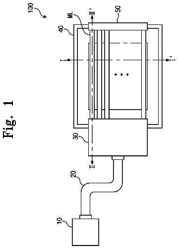
FIG. 1 is a perspective view of an information recording and reproducing device according to a first embodiment;
FIG. 2 is a side sectional view taken along a line II-II in FIG. 1 ;
FIG. 3 is an enlarged sectional view of a main part of a bearing device according to the first embodiment;
FIG. 4 is a plan view of a retainer according to the first embodiment;
FIG. 5 is a flowchart for explaining a manufacturing method for the bearing device according to the first embodiment;
FIG. 6 is a process drawing showing the manufacturing method for the bearing device according to the first embodiment and is a sectional view in a portion corresponding to the line II-II in FIG. 1 ;
FIG. 7 is a process drawing showing the manufacturing method for the bearing device according to the first embodiment and is a sectional view in the portion corresponding to the line II-II in FIG. 1 ;
FIG. 8 is a process drawing showing the manufacturing method for the bearing device according to the first embodiment and is a sectional view in the portion corresponding to the line II-II in FIG. 1 ;
FIG. 9 is a process drawing showing the manufacturing method for the bearing device according to the first embodiment and is a sectional view in the portion corresponding to the line II-II in FIG. 1 ;
FIG. 10 is an explanatory diagram of a bearing device according to a first modification of the first embodiment and is a sectional view in a portion corresponding to the line II-II in FIG. 1 ;
FIG. 11 is an explanatory diagram of a bearing device according to a second modification of the first embodiment and is a sectional view in a portion corresponding to the line II-II in FIG. 1 ;
FIG. 12 is an explanatory diagram of a bearing device according to a second embodiment and is a sectional view in a portion corresponding to the line II-II in FIG. 1 ;
FIG. 13 is an explanatory diagram of a bearing device according to a first modification of the second embodiment and is a sectional view in a portion corresponding to the line II-II in FIG. 1 ;
FIG. 14 is an explanatory diagram of a bearing device according to a second modification of the second embodiment and is a sectional view in a portion corresponding to the line II-II in FIG. 1 ;
FIG. 15 is an explanatory diagram of a bearing device according to a third embodiment and is a sectional view in a portion corresponding to the line II-II in FIG. 1 ;
FIG. 16 is a flowchart for explaining a manufacturing method for a bearing device according to the third embodiment;
FIG. 17 is a process diagram showing the manufacturing method for the bearing device according to the third embodiment and is a sectional view in a portion corresponding to the line II-II in FIG. 1 ;
FIG. 18 is a process diagram showing the manufacturing method for the bearing device according to the third embodiment and is a sectional view in the portion corresponding to the line II-II in FIG. 1 ;
FIG. 19 is a process diagram showing the manufacturing method for the bearing device according to the third embodiment and is a sectional view in the portion corresponding to the line II-II in FIG. 1 ; and
FIG. 20 is an explanatory diagram showing a bearing device according to a fourth embodiment and is a sectional view in a portion equivalent to line II-II in FIG. 1 ;
Detailed description of the invention
Embodiments of the present invention are explained below with reference to the drawings. First Embodiment
First, an information recording and reproducing device 1 and a bearing device 10 in a first embodiment are explained. Information recording and reproducing device
FIG. 1 is a perspective view of the information recording and reproducing device according to the first embodiment.
As shown in FIG. 1 , the information recording and reproducing device 1 is a device that performs writing and reading on a disk D (a magnetic recording medium) including a recording layer. The information recording and reproducing device 1 includes an arm 8 (a turning member), a head gimbal assembly 4 supported on the distal end side of the arm 8 , a slider 2 attached to the distal end of the head gimbal assembly 4 , an actuator (VCM: voice coil motor) 6 that moves the head gimbal assembly 4 for scanning, a spindle motor 7 that rotates the disk D, a control unit 5 that supplies an electric current modulated according to information to the slider 2 , and a housing 9 that houses these components on the inside.
The housing 9 is made of a metal material such as aluminum, iron, or stainless steel and is a box-shaped housing including an opening in an upper part. The housing 9 is configured by a bottom section 9 a having a square shape in plan view and a peripheral wall (not shown in the figure) vertically erected from a peripheral edge portion of the bottom section 9 a . A housing recessed section that houses the components is formed on the inner side of the housing 9 surrounded by the peripheral wall. The spindle motor 7 is attached to the substantial center of the bottom section 9 a . The disk D is detachably fixed by fitting a center hole in the spindle motor 7 .
The bearing device 10 is disposed in a side direction of the disk D. One side end portion of the bearing device 10 is supported by the bottom section 9 a of the housing 9 . The arm 8 is externally fit and fixedly attached to the outer circumferential surface of the bearing device 10 . The proximal end portion of the arm 8 is connected to the actuator 6 . The arm 8 is extended in parallel to the surface of the disk D from the proximal end side toward the distal end side.
The head gimbal assembly 4 is connected to the distal end of the arm 8 . The head gimbal assembly 4 includes a suspension 3 and the slider 2 attached to the distal end of the suspension 3 and disposed to be opposed to the surface of the disk D. The slider 2 includes a recording element that performs writing (recording) of information in the disk D and a reproducing element that performs reading (reproduction) of information from the disk D.
In the information recording and reproducing device 1 configured as explained above, to perform recording or reproduction of information, first, the spindle motor 7 is driven to rotate the disk D around a center axis L 2 of the disk D. The actuator 6 is driven to turn the arm 8 with the bearing device 10 set as a turning center. Consequently, the slider 2 disposed at the distal end of the head gimbal assembly 4 can be moved to scan sections on the surface of the disk D. Recording or reproduction of information on the disk D can be performed by driving the recording element or the reproducing element of the slider 2 .
Bearing Device
FIG. 2 is a side sectional view taken along a line II-II in FIG. 1 .
As shown in FIG. 2 , the bearing device 10 includes a shaft 20 and a roller bearing 11 externally inserted over the shaft 20 .
Note that, in the following explanation, a direction along the center axis (a center axis of the shaft 20 ) L 1 of the bearing device 10 is referred to as “axial direction”. A direction orthogonal to the center axis L 1 is referred to as “radial direction”. A direction around the center axis L 1 is referred to as “circumferential direction”.
The shaft 20 is formed of a metal material such as aluminum or stainless steel in a columnar shape and connected to the housing 9 (see FIG. 1 ). A flange 25 is formed on the axial direction one side of the shaft 20 . In the shaft 20 , a recessed section 27 opened on the axial direction both end faces of the shaft 20 is formed. The recessed section 27 pierces through the shaft 20 in the axial direction. The recessed section 27 is disposed coaxially with the center axis L 1 . The recessed section 27 is expanded in diameter on one side (a side on which the flange 25 is formed) in the axial direction of the shaft 20 .
The roller bearing 11 includes an inner ring 30 disposed coaxially with the center axis L 1 , an outer ring 40 surrounding the inner ring 30 from the outer side in the radial direction, a plurality of (in this embodiment, nine) rolling elements 15 formed in a spherical shape and held between the inner ring 30 and the outer ring 40 to be capable of rolling, and a retainer 50 that holds the rolling elements 15 to be capable of rolling. A dimension in the axial direction of the roller bearing 11 is equivalent to the dimension of the arm 8 . The roller bearing 11 overlaps the arm 8 in the entire axial direction.
The inner ring 30 is formed of a metal member in an annular shape and externally inserted over the shaft 20 . The inner ring 30 is divided into an inner ring one half section 31 (one half section) disposed on one side (the flange 25 side of the shaft 20 ) in the axial direction and an inner ring other half section 32 (the other half section) disposed on the other side in the axial direction.
The inner ring one half section 31 is formed in an annular shape extending along the axial direction. The axial direction both end faces of the inner ring one half section 31 are formed in a plane shape extending along the radial direction. At the end portion on the inner ring other half section 32 side (the other side) in the axial direction in the outer circumferential surface of the inner ring one half section 31 , a one half section rolling surface 31 a (a contact surface) gradually reduced in diameter from the axial direction one side toward the other side is formed over the entire circumference. The one half section rolling surface 31 a is formed in an arcuate shape in a sectional view passing the center axis L 1 (hereinafter referred to as “longitudinal sectional view”) and directed to the radial direction outer side and the axial direction other side. A curvature radius of the one half section rolling surface 31 a is larger than the radius of the rolling element 15 . The rolling element 15 is capable of coming into contact with the one half section rolling surface 31 a . The inner ring one half section 31 is in contact with the flange 25 of the shaft 20 from the axial direction other side.
The inner ring other half section 32 is formed surface-symmetrically to the inner ring one half section 31 with respect to a surface orthogonal to the center axis L 1 . That is, at the end portion on the inner ring one half section 31 side (one side) in the axial direction in the outer circumferential surface of the inner ring other half section 32 , an other half section rolling surface 32 a (a contact surface) gradually reduced in diameter from the axial direction other side toward the one side is formed over the entire circumference. The other half section rolling surface 32 a is formed in an arcuate shape in the longitudinal sectional view and directed to the radial direction outer side and the axial direction one side. The rolling element 15 is capable of coming into contact with the other half section rolling surface 32 a . The inner ring other half section 32 is disposed to be separated from the inner ring one half section 31 in the axial direction.
The outer ring 40 is formed of a metal material in a cylindrical shape extending along the axial direction. A dimension in the axial direction of the outer ring 40 is equivalent to the dimension of the inner ring 30 . In the center in the axial direction in the inner circumferential surface of the outer ring 40 , a rolling groove 48 is formed over the entire circumference along the circumferential direction. In the rolling groove 48 , a first rolling surface 40 a (a contact surface) provided on the axial direction one side and a second rolling surface 40 b (a contact surface) provided on the axial direction other side are provided. The first rolling surface 40 a is formed in an arcuate shape in the longitudinal sectional view gradually expanded in diameter from the axial direction one side toward the other side. The first rolling surface 40 a is directed to the radial direction inner side and the axial direction other side. A curvature radius of the first rolling surface 40 a is larger than the radius of the rolling element 15 . The second rolling surface 40 b is formed surface-symmetrically to the first rolling surface 40 a with respect to the surface orthogonal to the center axis L 1 . The second rolling surface 40 b is directed to the radial direction inner side and the axial direction one side. The rolling element 15 is capable of coming into contact with the first rolling surface 40 a and the second rolling surface 40 b.
The rolling element 15 is formed of a metal material. The rolling element 15 is in contact with the one half section rolling surface 31 a , the other half section rolling surface 32 a , and the first rolling surface 40 a and the second rolling surface 40 b of the rolling groove 48 and configured to roll along the circumferential direction between the inner ring 30 and the outer ring 40 . The one half section rolling surface 31 a of the inner ring one half section 31 is in contact with, from the axial direction one side toward the axial direction other side, a portion of the rolling element 15 facing the radial direction inner side. The other half section rolling surface 32 a of the inner ring other half section 32 is in contact with, from the axial direction other side toward the axial direction one side, the portion of the rolling element 15 facing the radial direction inner side. Further, the first rolling surface 40 a of the outer ring 40 is in contact with, from the axial direction one side toward the axial direction other side, the portion of the rolling element 15 facing the radial direction outer side. The second rolling surface 40 b of the outer ring 40 is in contact with, from the axial direction other side toward the axial direction one side, the portion of the rolling element 15 facing the radial direction outer side.
FIG. 3 is an enlarged sectional view of a main part of the bearing device according to the first embodiment.
The rolling element 15 is in contact with the one half section rolling surface 31 a and the first rolling surface 40 a in the same position in the axial direction. The rolling element 15 is in contact with the other half section rolling surface 32 a and the second rolling surface 40 b in the same position in the axial direction. In the longitudinal sectional view, a contact angle θ of the rolling element 15 and the other half section rolling surface 32 a with respect to the radial direction is smaller than 45° (see FIG. 3 ). The same applies to a contact angle of the rolling element 15 and the one half section rolling surface 31 a and a contact angle of the first rolling surface 40 a and the second rolling surface 40 b . The plurality of rolling elements 15 are annularly uniformly arrayed along the circumferential direction to be capable of rolling by the retainer 50 .
FIG. 4 is a plan view of the retainer according to the first embodiment.
As shown in FIGS. 2 and 4 , the retainer 50 is formed of a resin material or the like in an annular plate shape and disposed coaxially with the center axis L 1 . The inner diameter of the retainer 50 is slightly larger than the outer diameter of the shaft 20 . The outer diameter of the retainer 50 is approximately the inner diameter of the outer ring 40 . In the retainer 50 , ball pockets 51 , into which the rolling elements 15 can be inserted, are formed according to the number of rolling elements 15 . The ball pockets 51 are recessed from the outer circumferential surface of the retainer 50 toward the radial direction inner side. The ball pockets 51 are formed at equal intervals in the circumferential direction. At the inner circumferential edge of the retainer 50 , a thick section 53 projecting to the axial direction both sides is continuously formed over the entire circumference along the circumferential direction. The thick section 53 is formed further on the radial direction inner side than the ball pockets 51 . The thickness of the thick section 53 is smaller than a gap between the inner ring one half section 31 and the inner ring other half section 32 . The retainer 50 is disposed such that the thick section 53 is located between the inner ring one half section 31 and the inner ring other half section 32 . Note that the thick section 53 may be discontinuously formed along the circumferential direction.
As shown in FIG. 2 , the inner ring one half section 31 and the inner ring other half section 32 are fixed to the shaft 20 by press-fitting, bonding, welding, or the like. In this case, preloads are applied to the inner ring one half section 31 and the inner ring other half section 32 in directions in which the inner ring one half section 31 and the inner ring other half section 32 come close to each other. Specifically, the inner ring other half section 32 is fixed to the shaft 20 in a state in which the inner ring other half section 32 is pressed toward the inner ring one half section 31 side. The inner ring other half section 32 is pressed, whereby the inner ring one half section 31 is pressed toward the flange 25 side via the rolling element 15 . Since the inner ring one half section 31 is in contact with the flange 25 from the axial direction other side, movement to the axial direction one side is regulated. Consequently, preloads are applied to the inner ring one half section 31 and the inner ring other half section 32 in directions in which the inner ring one half section 31 and the inner ring other half section 32 come close to each other.
A manufacturing method for the bearing device 10 according to this embodiment is explained.
FIG. 5 is a flowchart for explaining the manufacturing method for the bearing device according to the first embodiment. FIGS. 6 to 9 are process drawings showing the manufacturing method for the bearing device according to the first embodiment and are sectional views in a portion corresponding to the line II-II in FIG. 1 .
As shown in FIG. 5 , the manufacturing method for the bearing device 10 according to this embodiment includes a one half section disposing step S 10 , a retainer disposing step S 20 , a rolling element disposing step S 30 , an other half section disposing step S 40 , and a preload applying step S 50 .
First, the one half section disposing step S 10 is performed. As shown in FIG. 6 , in the one half section disposing step S 10 , the outer ring 40 and the inner ring one half section 31 of the inner ring 30 are inserted over the shaft 20 . The inner ring one half section 31 is fixed to the shaft 20 .
Specifically, first, the shaft 20 is placed on a block-like jig P. In the jig P, a recessed section corresponding to the flange 25 of the shaft 20 is formed. The shaft 20 is placed such that a surface facing the axial direction other side of the flange 25 is flush with the principal plane of the jig P. Subsequently, the inner ring one half section 31 is externally inserted over the shaft 20 and fixed to the shaft 20 in a state in which the inner ring one half section 31 is set in contact with the flange 25 . The fixing of the inner ring one half section 31 and the shaft 20 is performed by press-fitting, bonding, welding, and the like. The outer ring 40 is externally inserted over the shaft 20 and placed on the principal plane of the jig P. Consequently, the end face on the axial direction one side of the inner ring one half section 31 and the end face on the axial direction one side of the outer ring 40 are located in the same position in the axial direction. Note that the shape of the jig P is not limited to the form shown in the figure and may be changed as appropriate.
Subsequently, the retainer disposing step S 20 is performed. As shown in FIG. 7 , in the retainer disposing step S 20 , the retainer 50 is disposed.
Specifically, the retainer 50 is externally inserted over the shaft 20 and placed on the end face on the axial direction other side of the inner ring one half section 31 .
Subsequently, the rolling element disposing step S 30 is performed. As shown in FIG. 8 , in the rolling element disposing step S 30 , the rolling element 15 is disposed from the other side in the axial direction.
Specifically, the plurality of rolling elements 15 are respectively inserted between the outer ring 40 and the shaft 20 from the other side in the axial direction. Further, the rolling elements 15 are pushed in toward the ball pockets 51 (see FIG. 7 ) of the retainer 50 . Consequently, the rolling elements 15 are disposed between the one half section rolling surface 31 a of the inner ring one half section 31 and the rolling groove 48 in a state in which the rolling elements 15 are held by the retainer 50 .
Subsequently, the other half section disposing step S 40 is performed. As shown in FIG. 9 , in the other half section disposing step S 40 , the inner ring other half section 32 of the inner ring 30 is inserted into the shaft 20 .
Specifically, the inner ring other half section 32 is externally inserted over the shaft 20 to set the other half section rolling surface 32 a in contact with the rolling element 15 . Consequently, the rolling element 15 is disposed among the one half section rolling surface 31 a , the other half section rolling surface 32 a , and the rolling groove 48 .
Subsequently, the preload applying step S 50 is performed. In the preload applying step S 50 , the inner ring other half section 32 is fixed to the shaft 20 while being pressed toward the inner ring one half section 31 .
The description continues in the full USPTO document.
 Lapsed, fee not paid6 drawings