 Lapsed, fee not paid3 drawings
Industrial Equipment · US 9,933,193 B2
Air-conditioning apparatus
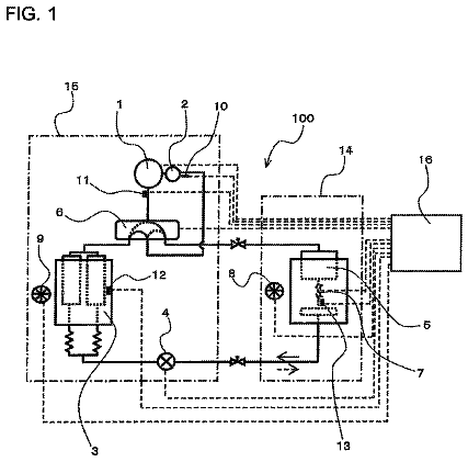
An air-conditioning apparatus includes a refrigeration cycle charged with non-azeotropic refrigerant mixture and refrigerating machine oil.
US 9,933,201 B2 · Assignee: LG Electronics Inc. · Inventors: Yi; Myeongha et al.
Sheet 1 of 12 from the published document. All sheets in the USPTO PDF
A refrigerator that includes a cabinet; a storage compartment located in the cabinet; a door mounted to the cabinet and configured to open or close at least a portion of the storage compartment; a freezing compartment provided in an upper region of the cabinet; an evaporator configured to cool the freezing compartment; an elevating frame provided at a lower part of the freezing compartment, the elevating frame being configured to move vertically and defining an expanded freezing compartment based on the elevating frame being moved downward; and fixed frames that are secured to respective sidewalls of the storage compartment and that are configured to guide and support vertical movement of the elevating frame is disclosed.
A refrigerator is an apparatus keeping foods fresh using cold air generated by a refrigeration cycle. For example, a refrigerator may include a compressor, a condenser, an expansion valve, and an evaporator.
8 of 12 drawing sheets so far from the published document, cropped to the drawing. Every sheet is in the USPTO PDF.
What the patent claimed, word for word. All of it is now free to use.
Pursuant to 35 U.S.C. § 119(a), this application claims the benefit of Korean Patent Application No. 10-2014-0173106, filed on, Dec. 4, 2014, which is hereby incorporated by reference as if fully set forth herein.
The present disclosure generally relates to a refrigerator.
A refrigerator is an apparatus keeping foods fresh using cold air generated by a refrigeration cycle. For example, a refrigerator may include a compressor, a condenser, an expansion valve, and an evaporator.
A refrigerator has a structure that ensures the effective drainage of defrosting water to prevent the defrosting water from flowing.
In general, one aspect of the subject matter described in this specification may be embodied in a refrigerator that includes a cabinet; a storage compartment located in the cabinet; a door mounted to the cabinet and configured to open or close at least a portion of the storage compartment; a freezing compartment provided in an upper region of the cabinet; an evaporator configured to cool the freezing compartment; an elevating frame provided at a lower part of the freezing compartment, the elevating frame being configured to move vertically and defining an expanded freezing compartment based on the elevating frame being moved downward; and fixed frames that are secured to respective sidewalls of the storage compartment and that are configured to guide and support vertical movement of the elevating frame. The fixed frames provided at the respective sidewalls of the storage compartment include a pair of fixed guides, and the elevating frame includes a bottom plate portion extending from a first fixed guide to a second fixed guide in the pair of fixed guides. The refrigerator further includes a support bar pivotably provided between the elevating frame and the fixed frames, the support bar being configured to guide and support the vertical movement of the elevating frame. The refrigerator further includes a plurality of support bars pivotably provided between the elevating frame and the fixed frames, the plurality of support bars being configured to guide and support the vertical movement of the elevating frame, and each of the support bars is spaced apart from each other in a front-and-rear direction. Each of the plurality of support bars includes a pivot shaft portion rotatably mounted to the bottom plate portion of the elevating frame and configured to support the bottom plate portion across a horizontal direction; support shaft portions bent from both ends of the pivot shaft portion and configured to support the bottom plate portion vertically; and mounting shaft portions bent from lower ends of the support shaft portions toward the fixed guides and connected to the fixed guides. The elevating frame is configured to be moved downward relative to the fixed frames as an angle between the bottom plate portion and the support shaft portions is decreased, and the elevating frame is supported at four or more points in all directions by the plurality of support bars. Each fixed frame has a vertical guide groove, and the elevating frame has a guide protrusion configured to be inserted into at least one vertical guide groove to guide vertical movement of the elevating frame. Each fixed guide has a support rib configured to support the elevating frame based on the elevating frame being moved downward. The elevating frame includes sidewall plate portions extending upward from both side ends of the bottom plate portion; and a shelf panel connected to upper ends of the sidewall plate portions and spaced upward apart from the bottom plate portion by a certain distance. The elevating frame defines a chiller chamber with the bottom plate portion, the sidewall plate portions, and the shelf panel. The refrigerator further includes a drawer configured to be pushed into or pulled out of the chiller chamber. The shelf panel is in contact with the evaporator based on the elevating frame being moved upward, and the expanded freezing compartment is defined between the evaporator and the shelf panel based on the elevating frame being moved downward. The shelf panel is charged with a cold storage material. The shelf panel is provided with a pivoting cover, and the pivoting cover is configured to pivot back and forth to open or close a front side of the expanded freezing compartment. The pivoting cover is configured to slide rearward along the shelf panel based on the elevating frame being moved upward. The evaporator includes an upper surface portion, a left side surface portion, and a right side surface portion, respectively defining an upper surface, a left side surface, and a right side surface of the freezing compartment. The evaporator further includes a rear surface portion defining a rear surface of the freezing compartment. The evaporator further includes a lower surface portion defining a lower surface of the freezing compartment, and the freezing compartment is defined as a fixed freezing compartment having a fixed capacity. The refrigerator further includes a freezing compartment door configured to open or close the fixed freezing compartment. The evaporator further includes a left extension and a right extension extending downward from the left side surface portion and the right side surface portion beyond the lower surface portion, and the left extension, the right extension, and the lower surface portion define the expanded freezing compartment based on the elevating frame being moved downward. The fixed frames are respectively provided with drain grooves, and the drain grooves are located below the left extension and the right extension such that defrosting water generated by the evaporator is introduced into the drain grooves. The elevating frame is provided at a rear portion of a drain groove such that defrosting water generated by the evaporator is introduced into the drain groove. The evaporator is a single plate, a rear surface portion of the evaporator is bent from a rear end of the lower surface portion, the upper surface portion is bent from an upper end of the rear surface portion, the left side surface portion is bent from a left end of the upper surface portion, and the right surface portion is bent from a right end of the upper surface portion. The lower surface portion is welded at left and right ends thereof to the left side surface portion and the right side surface portion to define the freezing compartment.
Another aspect of the subject matter described in this specification may be embodied in a refrigerator that includes a cabinet having a storage compartment; a door mounted to the cabinet configured to open or close at least a portion of the storage compartment; a freezing compartment defined in an upper region of the cabinet; a refrigerating compartment defined in a lower region of the cabinet; an evaporator configured to cool the freezing compartment; an elevating frame configured to define a chiller chamber between the freezing compartment and the refrigerating compartment, the elevating frame
provided at a lower part of the freezing compartment,
configured to move vertically, and
defining an expanded freezing compartment between the freezing compartment and the chiller chamber based on the elevating frame being moved downward; and fixed frames that are secured to respective sidewalls of the storage compartment and that are configured to guide and support vertical movement of the elevating frame.
Another aspect of the subject matter described in this specification may be embodied in a refrigerator that includes a cabinet having a storage compartment, the storage compartment being divided into a freezing compartment and a refrigerating compartment; a door mounted to the cabinet configured to open or close both the freezing compartment and the refrigerating compartment simultaneously; and a freezing compartment assembly provided in an upper region of the cabinet to define the freezing compartment separately from the refrigerating compartment, wherein the freezing compartment assembly includes an evaporator including an open front side, a left side surface portion, a right side surface portion, and a lower surface portion, the evaporator cooling the freezing compartment; an elevating frame provided below the lower surface portion, the elevating frame configured to move vertically and defining an expanded freezing compartment based on the elevating frame being moved downward; and fixed frames that are secured to respective sidewalls of the storage compartment and that are configured to guide and support vertical movement of the elevating frame, the fixed frames defining a space for vertical movement of the elevating frame therein. The evaporator further includes an upper surface portion and a lower surface portion, and the freezing compartment has a substantially cuboidal inner space such that a front side of the freezing compartment is open. The evaporator includes a left extension and a right extension extending downward from lower ends of the left side surface portion and the right side surface portion, and wherein the left extension and the right extension are connected respectively to the fixed frames provided in both sides of the storage compartment. Each fixed frame is provided on an upper surface of a drain groove, and the drain groove is configured to receive defrosting water introduced from the left extension or the right extension. The elevating fame includes a bottom plate portion extending from one fixed frame to the remaining fixed frame; a shelf plate spaced upward apart from the bottom plate portion configured to define a chiller chamber between the shelf plate and the bottom plate; a left sidewall plate portion and a right sidewall plate portion provided to connect both ends of the bottom plate portion and the shelf plate to each other; and a drawer configured to be pulled into or pushed out of the chiller chamber. The freezing compartment assembly further includes a support bar pivotably provided between the elevating frame and the fixed frames, the support bar having a support shaft portion configured to support the elevating frame while moving the elevating frame downward as an angle between the bottom plate portion and the support shaft portion is decreased from a right angle to a certain angle, the support shaft portion forming support points arranged to support at least four locations, including front and rear locations and left and right locations, of the elevating frame.
These and other embodiments may each optionally include one or more of the following features. For instance, variable adjustment of the size of a freezing compartment may be accomplished via movement of a partition wall between the freezing compartment and a refrigerating compartment.
In addition, defrosting water generated on an evaporator installed near the freezing compartment may be effectively drained so as to prevent the defrosting water from flowing to a drive device which moves the partition wall.
Moreover, the effective cooling of a variable freezing space as well as a fixed freezing space may be accomplished.
The details of one or more embodiments of the subject matter described in this specification are set forth in the accompanying drawings and the description below. Other potential features, aspects, and advantages of the subject matter will become apparent from the description, the drawings, and the claim.
FIG. 1 is a diagram illustrating an example refrigerator.
FIGS. 2 to 6B are diagrams illustrating an example freezing compartment assembly.
FIG. 7 is a diagram illustrating example refrigerant pipes in an evaporator.
FIG. 8 is a diagram illustrating an example flow of refrigerant in the evaporator.
FIGS. 9A and 9B are diagrams illustrating an example state in which an elevating frame is at a downwardly moved position and a pivoting cover blocks the front of an increased freezing compartment space.
FIGS. 10A and 10B are diagrams illustrating an example state that the elevating frame is moved downwardly and the pivoting cover is pivotably rotated and pushed inward to open the front of the increased freezing compartment space.
FIGS. 11A and 11B are diagrams illustrating an example state that the elevating frame is moved upwardly.
FIG. 12 is a diagram illustrating an example state that a drawer is pulled-out.
FIG. 1 illustrates an example refrigerator. The refrigerator may include a freezing compartment 22 and a refrigerating compartment 21 , which constitute a storage compartment 20 inside a cabinet 10 . For example, the storage compartment 20 , which is a single storage region defined by the cabinet 10 , may be divided into the freezing compartment 22 and the refrigerating compartment 21 . The freezing compartment 22 may be provided within a freezing compartment assembly 100 . For example, the freezing compartment 22 may be separated from the refrigerating compartment 21 via the freezing compartment assembly 100 that is mounted in a partial region of the storage compartment 20 .
A single door 30 may be pivotably mounted at one side of the cabinet 10 and serve to open or close the freezing compartment 22 and the refrigerating compartment 21 . For example, by opening the single door 30 , a user can access the freezing compartment 22 and the refrigerating compartment 21 in the storage compartment 20 which is a single storage region.
A plurality of baskets 32 having various shapes and sizes may be mounted to an inner surface of the door 30 .
A shelf 40 may be provided in the refrigerating compartment 21 , and the refrigerating compartment 21 may be divided into a plurality of sub storage regions by the shelf 40 . For example, an upper region and a lower region may be separated by a shelf. In some implementations, the shelf 40 may be slidably supported by a shelf guide 41 . When at least a part of the shelf 40 is removed, at least a part of the upper region and the lower region may be merged. Thus, a container, which is taller than one sub storage region, may be stored in the refrigerating compartment 21 .
A drawer 50 may be provided in the lower section of the refrigerating compartment 21 . In some implementations, the drawer 50 can be a part of the refrigerating compartment 21 . The drawer 50 may be configured to define a space isolated from the remaining region of the refrigerating compartment 21 , in order to prevent moisture evaporation. For example, the drawer 50 may be used to store vegetables or fruits.
The freezing compartment 22 may be provided in an upper region of the cabinet 10 . In particular, the freezing compartment 22 may be provided in the upper region of the storage compartment 20 inside the cabinet 10 .
The example refrigerator may be configured to increase or decrease a space in the freezing compartment 22 by controlling the volume of the freezing compartment 22 . For example, the example refrigerator may increase the volume of the freezing compartment 22 , beyond the basic volume of the freezing compartment 22 , as needed. If the volume of the freezing compartment 22 increases, the volume of the refrigerating compartment 21 may be reduced. Thus, the freezing compartment assembly 100 may be configured to vary the storage space in the freezing compartment 22 by controlling the volume of the freezing compartment 22 . In particular, this variation may be implemented via the upward/downward movement of a partition wall provided in the freezing compartment assembly 100 .
The volume of the entire freezing compartment 22 may be changed by moving the partition wall vertically. For example, the freezing compartment 22 may have the minimum basic volume at the highest position, i.e. the default position at which the partition wall is moved upward to the maximum extent. Then, the volume of the freezing compartment 22 may be increased as the partition wall is moved downward. Once the partition wall has been moved downward to the maximum extent, the volume of the freezing compartment 22 may be increased to the maximum extent. On the other hand, the volume of the refrigerating compartment 21 may be minimized.
In some implementations, in the freezing compartment 22 , an upper space may be a fixed space and a lower space may be a variable space defined by the vertically moving partition wall. In some other implementations, the space above a fixed partition wall may become a fixed freezing compartment space, and a variable freezing compartment space may be defined between the fixed partition wall and a vertically moving partition wall which is located below the fixed partition wall. For example, when the two partition walls are located so as to come into close contact with each other, the total space in the freezing compartment is minimized, and when the two partition walls are located farthest from each other, the variable space is maximized, i.e. the overall amount of space in the freezing compartment may become the maximum.
FIGS. 2 to 5 illustrate an example freezing compartment assembly 100 . In the above description, for convenience of description, although a component, which separates the freezing compartment and the refrigerating compartment from each other, is named the partition wall, as will be described below, the partition wall may take the form of a singular component, or may take the form of plural components.
As described above, the space or volume of the freezing compartment may vary. As the space or volume of the freezing compartment varies, the space or volume of the refrigerating compartment varies. In some implementations, a freezing compartment may not be expandable. The freezing compartment can be fixed.
The freezing compartment 110 , i.e. the basic freezing compartment 110 may define a cuboidal space, the front of which is open. Specifically, the basic freezing compartment 110 may be provided in a space inside an evaporator 200 which takes the form of a cuboid having an open front side. The freezing compartment 110 , provided in the inner space defined by the evaporator 200 , may be referred to as a freezing space having a fixed size or capacity. For example, the freezing compartment 110 can be defined as a fixed freezing compartment having a fixed size or capacity. In this case, although will be described below, both side surfaces and top and bottom surfaces of the freezing compartment 110 may be formed by the evaporator 200 , and a rear surface of the freezing compartment 110 may also be formed by the evaporator 200 . In addition, although the lower surface of the freezing compartment 110 may be formed by the evaporator 200 , the lower surface of the freezing compartment 110 may be formed by any other component, instead of the evaporator 200 .
A pair of fixed frames 300 may be installed underneath the freezing compartment 110 . The fixed frames 300 are fixed to both sidewalls of the storage compartment.
Each of the fixed frames 300 may have at least two fastening holes 302 , so as to be fastened and fixed to an inner side wall of the storage compartment via fastening members such as, for example, screws.
An elevating frame 400 may be provided at a lower part of the freezing compartment 110 . In particular, the elevating frame 400 may be provided between the fixed frames 300 . The freezing compartment space increases as the elevating frame 400 is moved downward. Although will be described below, the elevating frame 400 may define a storage space therein. The storage space may be an additional storage space provided between the freezing compartment and the refrigerating compartment. For example, the storage space may be maintained at a low temperature that falls in an intermediate range between the respective temperatures of the freezing compartment and the refrigerating compartment, and may be referred to as a chiller chamber.
The evaporator 200 may be fabricated by laying a refrigerant pipe between two metal plates and fusing the two plates to each other.
Although the evaporator 200 may be installed so as to be supported by the fixed frames 300 which are installed to both sidewalls of the storage compartment, the evaporator 200 may have at least two screwing holes 202 so as to be fastened to the ceiling surface and side surfaces of the storage compartment.
The freezing compartment 110 may generally have a cuboidal shape, and the evaporator 200 may have five surfaces, i.e. the fix surfaces of a cuboid excluding a front surface thereof.
A freezing compartment door 130 may be pivotably mounted to the front side of the freezing compartment 110 . For example, in order to prevent cold air, inside the freezing compartment 110 of the storage compartment 20 , from entering the refrigerating compartment 21 , the freezing compartment door 130 may be provided. The freezing compartment door 130 may be a door operated after the main door 20 is opened.
For the mounting of the freezing compartment door 130 , and consequently, for the opening or closing of the freezing compartment 110 , a door frame 120 may be provided at the front surface of the evaporator 200 . In addition, pivot shafts 123 may be provided at upper and lower ends of one side (e.g. a right side or a left side) of the door frame 120 .
A handle 132 may be provided at the other side (e.g. a left side or a right side) of the freezing compartment door 130 . The handle 132 may include a portion protruding from a front surface of the freezing compartment door 130 and a recess indented in the front surface. With the above-described configuration of the freezing compartment 110 and the freezing compartment door 130 , the basic freezing compartment 110 may be acquired. For example, the effect of realizing a dual door refrigerator (i.e. a refrigerator in which a refrigerating compartment and a freezing compartment are separated from each other by a thermal insulation wall and are opened or closed by respective doors) may be acquired using a single door refrigerator (i.e. a refrigerator in which a refrigerating compartment and a freezing compartment are not separated from each other by a thermal insulation wall).
The elevating frame 400 may be vertically moved by a pair of support bars 500 , which are pivotably connected between the fixed frames 300 . In addition, the elevating frame 400 may be supported by the support bars 500 .
The support bars 500 may be arranged back and forth. Each support bar 500 may extend from one fixed frames 300 to the other fixed frames 300 . As such, at least four support points may be formed in different respective directions of the elevating frame 400 via the support bars 500 .
Thus, the elevating frame 400 may move stably in vertical directions with the support of the support bars 500 .
The support bars 500 are required to support the weight of the elevating frame 400 and stored items, and thus, may be formed of metal wires so as to achieve the sufficient strength thereof.
The elevating frame 400 may include a bottom plate portion 420 . When the bottom plate portion 420 is moved downward, it may be said that, on the basis of the bottom plate portion 420 , an upper space is expanded and a lower space is contracted. For example, a freezing compartment region can be expanded and a refrigerating compartment region can be contracted.
The elevating frame 400 may include a pair of sidewall plate portions 430 , which extend upward from both side ends of the bottom plate portion 420 . An additional storage space may be defined between the fixed freezing compartment 110 , the bottom plate portion 420 , and the sidewall plate portions 430 . The storage space may be a chiller chamber 900 . When the chiller chamber 900 defined by the elevating frame 400 is moved downward, the freezing space is increased. For example, although the simple vertical movement of the bottom plate portion 420 may be considered to vary the volume of the upper space and the lower space using a partition wall, the vertical movement of the chiller chamber 900 may be considered to vary the volume of the upper space and the lower space using a partition space.
In either case, when the elevating frame 400 is moved downward, the size of the variable freezing space is increased. When the elevating frame 400 is moved upward, the size of the variable freezing space is reduced, and correspondingly, a space in the refrigerating compartment 21 is increased.
Specifically, the support bars 500 may be pivotably mounted to a lower surface of the bottom plate portion 420 of the elevating frame 400 via bearings 540 .
Each of the support bars 500 may include a pivot shaft portion 510 rotatably mounted to the elevating frame 400 , support shaft portions 520 bent from both ends of the pivot shaft portion 510 , and mounting portions 530 bent from lower ends of the support shaft portions 520 so as to extend toward the fixed frames 300 . The pivot shaft portion 510 may be referred to as a horizontal shaft portion, and the support shaft portions 520 may be referred to as vertical shaft portions.
When an angle between the support shaft portion 520 and the bottom plate portion 420 is 90 degrees, the bottom plate portion 420 is located at the highest position at which it is moved upward to the maximum extent. In addition, the smaller the angle between the support shaft portion 520 and the bottom plate portion 420 , the lower the height of the bottom plate portion 420 .
Each bearing 540 serves to horizontally mount the pivot shaft portion 510 . The bearing 540 may be fastened and fixed to the lower surface of the bottom plate portion 420 via two screws. As such, the bottom plate portion 420 is put on two wires which are spaced apart from each other in the front-and-rear direction and extend in the left-and-right direction. In addition, the bearing 540 may also serve to maintain the two pivot shaft portions 510 at a fixed front-and-rear distance.
The support bars 500 may be linked to each other. For example, the pivot shaft portions 510 , which face each other at the front and rear sides of the elevating frame 400 , may be rotated together. Specifically, all angles between the bottom plate portion 420 and the four support shaft portions 520 located on all sides of the bottom plate portion 420 may vary in the same manner. This is because it is desirable to allow the bottom plate portion 420 to be moved vertically while remaining horizontal.
Referring to FIG. 5 , the support bars 500 are connected to each other by a pair of left and right sliding bars 560 . As such, the support bars 500 may be operated only when the sliding bars 560 are equally moved at the same time. For example, the bottom plate portion 420 may be vertically moved via back and forth movement of the sliding bars 560 .
Specifically, each fixed frame 530 may have horizontal guide slots 320 formed in a lower portion thereof such that the two mounting shaft portions 530 are slidably inserted respectively. The horizontal guide slots 320 may be formed in the fixed frames 300 so as to extend in the front-and-rear direction. In addition, the horizontal guide slots 320 may be formed so as to allow penetration of the mounting shaft portions 530 . As such, the mounting shaft portions 530 may slide back and forth along the horizontal guide slots 320 .
The horizontal guide slots 320 may be formed in the lower portion of the fixed frames 300 . In addition, there horizontal guide slots 320 may be two front and rear horizontal guide slots. The mounting shaft portion 530 of the front support bar 500 may slide in the front horizontal guide slot 320 , and the mounting shaft portion 530 of the rear support bar 500 may slide in the rear horizontal guide slot 320 .
The horizontal guide slots 320 may be formed respectively in both the fixed frames 300 .
A length of each horizontal guide slot 320 may be determined in consideration of a length of the support shaft portion 520 of the support bar 500 , a distance between the two pivot shaft portions 510 , and a pivoting angle of the support bar 500 upon downward movement. For example, increasing the length of the horizontal guide slot 320 means that an angle between the bottom plate portion 420 and the support shaft portion 520 may be additionally reduced.
As described above, when the angle is 90 degrees, the bottom plate portion 420 may be at the highest position at which it is moved upward to the maximum extent. The bottom plate portion 420 is gradually moved downward as the angle is gradually reduced. At this time, the minimum angle may be 20 degrees or more. This is because it is very difficult to move the bottom plate portion 420 upward by applying force in the horizontal direction when the minimum angle is reduced to be less than 20 degrees. Accordingly, the length of the horizontal guide slot 320 may be determined such that the mounting shaft portion 530 is no longer moved when the angle reaches a predetermined minimum angle.
The sliding bars 560 may be provided at the respective fixed frames 300 . The mounting shaft portion 530 , having passed through the horizontal guide slot 320 , may be connected to the sliding bar 560 . The sliding bar 560 may be slidably mounted to an outer surface of the fixed frames 300 . One sliding bar 560 , i.e. the sliding bar 560 located at one side may be connected at front and rear ends thereof to the respective mounting shaft portions 530 so as to allow rotation of the mounting shaft portions 530 .
The fixed frames 300 may be provided with a boss 345 at the center of a lower portion of the outer surface thereof, i.e. at a position between the two horizontal guide grooves 320 , and the sliding bar 560 may be slidably mounted to the boss 345 as a screw 564 is fastened from the outer surface of the fixed frames 300 through an elongated hole 562 perforated in the sliding bar 560 .
The sliding bar 560 may have shaft holes 566 at left and right sides of the elongated hole 562 such that the mounting shaft portions 530 are pivotably inserted into the shaft holes 566 .
The sliding bar 560 may slide while being supported at three points by the screw 564 , which is fastened through the elongated hole 562 , and the two mounting shaft portions 530 which are inserted into the two shaft holes 566 and supported by the horizontal guide grooves 320 . This is because the mounting shaft portions 530 are basically slidably supported by the horizontal guide grooves 320 of the fixed frames 300 .
The sliding bars 560 may prevent the elevating frame 400 from tilting back and forth by allowing pivoting of the two support bars 500 to be synchronized such that the two support bars 500 pivot at the same angle.
In addition, the fixed frames 300 may further include vertical guide grooves 310 formed in a front portion of an inner surface thereof respectively. The elevating frame 400 may further include guide protrusions 410 , which protrude from outer side surfaces thereof and are inserted into the respective vertical guide grooves 310 so as to be vertically moved.
The vertical guide grooves 310 may be vertically elongated in the front portion of the inner surface of the respective fixed frames 300 , and the guide protrusions 410 may protrude laterally from the outer side surfaces of the elevating frame 400 .
Although the support bars 500 are pivotably mounted to the elevating frame 400 and support the elevating frame 400 , the provision of the pivoting support bars 500 may cause the elevating frame 400 to pivot, and thus, there is the possibility that the elevating frame 400 may be moved forward or rearward during vertical movement thereof. However, since the guide protrusions 410 of the elevating frame 400 are inserted into the vertical guide grooves 310 in the fixed frames 300 and are guided to be moved only in the vertical direction, the elevating frame 400 may be moved only in the vertical direction while remaining horizontal even when the support bars 500 pivot so as to move the elevating frame 400 vertically.
The fixed frames 300 may further include support ribs 330 , which are formed at inner surfaces of the fixed frames 300 and serve to support the elevating frame 400 at a downwardly moved position thereof. For example, the support ribs 330 may support the bottom plate portion 420 when the bottom plate portion 420 is moved downward to the maximum extent.
Two support ribs 330 may protrude from an inner side surface of each fixed frames 300 so as to support the elevating frame 400 at the downwardly moved position thereof.
If the support ribs 330 protrude to an excessively long length, the support ribs 300 can interfere with objects received in the refrigerating compartment 21 . Therefore, the support ribs 330 may have a thickness and length suitable for achieving a desired strength.
Meanwhile, a tensile spring 570 may be connected between one end of the sliding bar 560 and the outer side surface of the fixed frames 300 .
One end of the tensile spring 570 may be connected to a spring mounting protrusion 340 formed at the outer side surface of the fixed frames 300 , and the other end of the tensile spring 570 may be connected to one end of the sliding bar 560 , for example, a spring mounting protrusion 567 which protrudes upward from a rear end of an upper surface of the sliding bar 560 .
Referring to FIGS. 2 to 4 , while the elevating frame 400 is at the upwardly moved position, the tensile spring 570 applies elastic force required to pull the sliding bar 560 forward.
For example, as the mounting shaft portions 530 are inserted into the two shaft holes 566 of the sliding bar 560 , the tensile spring 570 applies elastic force to the mounting shaft portions 530 forward.
As such, even if the support bars 550 are slightly pushed or receive shocks in a state in which the support shaft portions 520 of the support bars 550 are substantially upright, the support bars 500 may not easily pivot and remain to support the elevating frame 400 .
Referring to FIGS. 5 to 6B , the elevating frame 400 may define an additional storage space. For example, the chiller chamber 900 may be defined between the basic freezing compartment 110 and the refrigerating compartment 21 . A drawer 600 may be mounted inside the elevating frame 400 so as to be pulled out. The user can use the chiller chamber 900 via the drawer 600 .
The drawer 600 may be provided with a grip recess ( 610 , see FIGS. 10A and 10B ) indented upward from a lower end of a front surface thereof.
The drawer 600 may include guide ribs 620 which protrude from outer side surfaces thereof, and the elevating frame 400 may further include guide grooves 440 which are formed in inner surfaces of the sidewall plate portions 430 and serve to guide the guide ribs 620 of the drawer 600 inserted thereinto.
The front surface of the drawer 600 may have a greater width than a width between both side surfaces of the drawer 600 and may be configured to close the open front side of the elevating frame 400 so as to define a hermetically sealed storage space.
The guide ribs 620 may be inclined so as to be gradually reduced in height rearward relative to a bottom surface of the drawer 600 . Correspondingly, the guide grooves 440 may be inclined so as to be gradually reduced in height rearward. In this way, the user may smoothly push the drawer 600 inward with low force.
In addition, referring to FIGS. 6A and 6B , each guide groove 440 may be provided at a front end thereof with a stepped portion 445 , and each guide rib 620 may be provided at a rear lower portion thereof with a protruding stopper 625 .
The guide rib 620 may be integrally formed at a rear end thereof with a contact protrusion 622 , which has a circular shape when viewed from the outer lateral side.
As such, a bottom surface of the guide groove 440 may come into contact with only lower surfaces of the circular contact protrusion 622 and the protruding stopper 625 , rather than coming into contact with the entire lower surface of the guide rib 620 . This may reduce a sliding contact area between the guide rib 620 and the guide groove 440 , which may reduce friction and ensure smooth sliding.
When the user pulls the drawer 600 out, the drawer 600 is pulled out only until the protruding stopper 625 is caught by the stepped portion 445 , which may limit the length of the drawer 600 that the drawer 600 can be pulled out to the maximum extent.
At any time while the drawer 600 is being pulled out, the contact protrusion 622 , which has been in contact with the lower surface of the guide groove 440 , may come into contact with an upper surface of the guide groove 440 so as to slide on the upper surface. In this case, downward rotational moment is applied to a portion of the drawer 600 that is in front of the stepped portion 445 .
When the drawer 600 is pulled out to the end, in particular, there is the risk of the drawer 600 falling out along with the items received therein. Therefore, by allowing the protruding stopper 625 to be caught by the stepped portion 445 , the distance that the drawer 600 can be pulled out is limited, which may ensure that the drawer 600 is stably supported by the guide groove 440 and may prevent the drawer 600 from falling out.
To completely remove the drawer 600 for cleaning, etc., the drawer 600 may be completely separated from the elevating frame 400 by being pulled in a state in which the front half of the drawer 600 is lifted slightly.
Accordingly, in this example, the elevating frame 400 enables the expansion of the freezing space as well as the formation of the chiller chamber 900 . In conclusion, it can be appreciated that the freezing space may vary via vertical movement of the entire chiller chamber 900 .
Meanwhile, the chiller chamber 900 should be isolated from the remainder of the space so as to define a somewhat hermetically sealed space. As described above, the front side of the chiller chamber 900 may be hermetically sealed by the front surface of the drawer 600 . Hereinafter, a configuration of the chiller chamber 900 defined by the elevating frame 400 will be described in detail.
Referring to FIGS. 3 and 5 , the elevating frame 400 may further include a shelf panel 800 disposed on the sidewall plate portions 430 . For example, the shelf panel 800 may be spaced upward apart from the bottom plate portion 420 by a predetermined distance. As such, the shelf panel 800 functions as an upper surface of the chiller chamber 900 , and the bottom plate portion 420 functions as a lower surface of the chiller chamber 900 .
In addition, the sidewall plate portions 430 may extend upward from both ends of the bottom plate portion 420 and be connected to the shelf panel 800 . As such, the respective sidewall plate portions 430 function as both side surfaces of the chiller chamber 900 . In addition, it will be appreciated that a rear surface of the chiller chamber 900 is formed by a rear wall of the storage space defined by the cabinet.
The shelf panel 800 can be a rectangular panel having a predetermined thickness. To mount the shelf panel 800 , panel mounting grooves 438 may be formed respectively in the top of the sidewall plate portions 430 .
The shelf panel 800 may internally define a space and a cold storage material formed of a phase change material may be introduced into the space. For example, the shelf panel 800 may include a cold storage pack.
Referring to FIG. 4 , the shelf panel 800 may be provided at the rear center thereof with an injection port 820 to enable injection of the cold storage material.
The description continues in the full USPTO document.
About 6,786 words. The USPTO PDF has it with every drawing.
Fees are due 3.5, 7.5 and 11.5 years after grant. This patent expired on April 3, 2026, so the fee marked "not paid" was the one that went unpaid.
REFRIGERATOR
Filed Dec 2015 · published Jun 2016Refrigerator
Filed Dec 2015 · granted Apr 2018Earlier publications, parents and continuations. None of them can still be enforced, or this patent would not be listed.
Prior art cited by the examiner or applicant. Useful when you check your own idea for novelty.
Everything on this page comes from the documents linked above.