Field
The present disclosure relates to transmission clutches and more particularly to a variable two-way over-running clutch.
Background
This section provides background information related to the present disclosure which is not necessarily prior art.
Transmission clutches often find utility in vehicles where they modulate the amount of torque applied to transmission components by an engine. Automatic transmissions provide smooth shifting between gears. Planetary and dual-clutch transmissions are two different forms of automatic transmissions. Planetary automatic transmissions may have lower gear sliding-related losses relative to dual-clutch transmissions because planetary automatic transmissions typically have smaller gear modules (shorter gear teeth) than those used in dual-clutch transmissions. In addition, planetary automatic transmissions often utilize lower viscosity lubricant for gear and clutch protection in comparison to dual-clutch transmissions. Nonetheless, planetary automatic transmissions are usually less efficient than dual-clutch transmissions because planetary automatic transmissions utilize a larger number of wet clutches (i.e., friction-plate clutches) in comparison to dual-clutch transmissions, which typically have switch-type clutches such as dog clutches.
Clutch inefficiency in planetary automatic transmissions comes primarily from the drag-related losses associated with spinning the disengaged friction plates of the wet clutches. While drag-related losses can be minimized by providing adequate spacing between the friction plates, such additional spacing typically results in longer shift times and larger overall packaging dimensions.
A dog clutch or other switch-type clutch arrangement may provide a more efficient clutch configuration in its disengaged state. However, use of such switch-type clutches does not allow for appropriate gradual energy dissipation and torque transfer, thereby resulting in abrupt gear shifts. Thus, while wet clutches provide a longer shift time when compared to dog clutches or other switch-type clutch arrangements (and therefore smoother shifts), wet clutches suffer from the disadvantage of spinning losses when disengaged. What is needed is a clutch assembly that has improved efficiency over conventional wet clutch assemblies and reduced noise, vibration, and harshness (smoother shifts) in comparison to dog clutch or other switch-type clutch arrangements.
Summary
This section provides a general summary of the disclosure, and is not a comprehensive disclosure of its full scope or all of its features.
In accordance with one aspect of the subject disclosure, a clutch assembly is provided that includes an first shaft, an inner race, an outer race, at least one torque transmitting member, and an actuator. The inner race is rotatably coupled to the first shaft and the outer race is disposed annularly about the inner race. Either the inner race or the outer race is moveable in a radial direction with respect to the first shaft. The at least one torque transmitting member is disposed between the outer race and the inner race. The at least one torque transmitting member selectively engages at least one of the outer race and the inner race to transfer torque from the inner race and, thus, the first shaft to the outer race such that the inner race and outer race rotate together.
The actuator is coupled to the inner race or the outer race. The actuator operably controls radial movement of the inner race or the outer race in the radial direction to provide selective lock-up of the inner race and the outer race. By controlling the radial movement of either the inner race or the outer race, the actuator adjusts the spacing of the inner race relative to the outer race at a location adjacent the at least one torque transmitting member. This allows the actuator to control whether or not the at least one torque transmitting member is engaged. In accordance with another aspect of the subject disclosure, at least one of the inner race and the outer race may include at least one cam that receives the at least one torque transmitting member. The at least one cam has a ramped surface configured to contact the at least one torque transmitting member.
Advantageously, the clutch assembly set forth in the subject disclosure eliminates the spinning losses associated with a disengaged wet clutch assembly and thus provide greater efficiency in comparison to conventional wet clutch assemblies. At the same time, the clutch assembly of the subject disclosure results in less noise, vibration, and harshness when compared to conventional dog clutch assemblies due to its ability to gradually transfer torque between the first shaft and the outer race, which may be rotatably coupled to a housing. This results in smoother shifts.
Further areas of applicability will become apparent from the description provided herein. The description and specific examples in this summary are intended for purposes of illustration only and are not intended to limit the scope of the present disclosure.
Drawings
The drawings described herein are for illustrative purposes only of selected embodiments and not all possible implementations, and are not intended to limit the scope of the present disclosure.
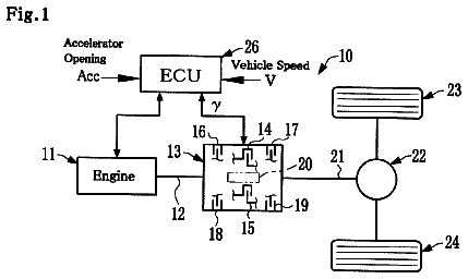
FIG. 1 is a schematic representation of a vehicle incorporating a transmission in accordance with the principles of the present disclosure;
FIG. 2 is a side cross-sectional view of an exemplary clutch assembly constructed in accordance with the principles of the present disclosure and for use with the transmission shown in FIG. 1 ;
FIG. 3 is a side cross-sectional view of another exemplary clutch assembly constructed in accordance with the principles of the present disclosure and for use with the transmission shown in FIG. 1 ;
FIG. 4A is a front cross-sectional view of another exemplary clutch assembly constructed in accordance with the principles of the present disclosure where an inner race is shown in an eccentric position;
FIG. 4B is another front cross-sectional view of the exemplary clutch assembly shown in FIG. 4A where the inner race is shown in a concentric position;
FIG. 4C is another front cross-sectional view of the exemplary clutch assembly shown in FIGS. 4A and 4B where the inner race is shown in another eccentric position;
FIG. 5 is a front cross-sectional view of another exemplary clutch assembly constructed in accordance with the principles of the present disclosure;
FIG. 6A is a front cross-sectional view of another exemplary clutch assembly constructed in accordance with the principles of the present disclosure;
FIG. 6B is another front cross-sectional view of the exemplary clutch assembly shown in FIG. 6A where the inner race has been shifted counter-clockwise relative to its position in FIG. 6A ;
FIG. 6C is another front cross-sectional view of the exemplary clutch assembly shown in FIGS. 6A and 6B where the inner race has been shifted counter-clockwise relative to its position in FIG. 6B ;
FIG. 6D is another front cross-sectional view of the exemplary clutch assembly shown in FIGS. 6A-6C where the inner race has been shifted counter-clockwise relative to its position in FIG. 6C ;
FIG. 7A is a front cross-sectional view of another exemplary clutch assembly constructed in accordance with the principles of the present disclosure where the inner race is shown in an eccentric position;
FIG. 7B is another front cross-sectional view of the exemplary clutch assembly shown in FIG. 7A where the inner race is shown in another eccentric position;
FIG. 8 is a front cross-sectional view of another exemplary clutch assembly constructed in accordance with the principles of the present disclosure where a retainer is shown that maintains the position of several torque transmitting members;
FIG. 9 is a front cross-sectional view of another exemplary clutch assembly constructed in accordance with the principles of the present disclosure where the exemplary clutch assembly includes an eccentric first shaft; and
FIG. 10 is a front cross-sectional view of another exemplary clutch assembly constructed in accordance with the principles of the present disclosure where the exemplary clutch assembly includes an eccentric outer race.
Corresponding reference numerals indicate corresponding parts throughout the several views of the drawings.
Detailed description
Example embodiments will now be described more fully with reference to the accompanying drawings.
Example embodiments are provided so that this disclosure will be thorough, and will fully convey the scope to those who are skilled in the art. Numerous specific details are set forth such as examples of specific components, devices, and methods, to provide a thorough understanding of embodiments of the present disclosure. It will be apparent to those skilled in the art that specific details need not be employed, that example embodiments may be embodied in many different forms and that neither should be construed to limit the scope of the disclosure. In some example embodiments, well-known processes, well-known device structures, and well-known technologies are not described in detail.
The terminology used herein is for the purpose of describing particular example embodiments only and is not intended to be limiting. As used herein, the singular forms “a,” “an,” and “the” may be intended to include the plural forms as well, unless the context clearly indicates otherwise. The terms “comprises,” “comprising,” “including,” and “having,” are inclusive and therefore specify the presence of stated features, integers, steps, operations, elements, and/or components, but do not preclude the presence or addition of one or more other features, integers, steps, operations, elements, components, and/or groups thereof. The method steps, processes, and operations described herein are not to be construed as necessarily requiring their performance in the particular order discussed or illustrated, unless specifically identified as an order of performance. It is also to be understood that additional or alternative steps may be employed.
When an element or layer is referred to as being “on,” “engaged to,” “connected to,” or “coupled to” another element or layer, it may be directly on, engaged, connected or coupled to the other element or layer, or intervening elements or layers may be present. In contrast, when an element is referred to as being “directly on,” “directly engaged to,” “directly connected to,” or “directly coupled to” another element or layer, there may be no intervening elements or layers present. Other words used to describe the relationship between elements should be interpreted in a like fashion (e.g., “between” versus “directly between,” “adjacent” versus “directly adjacent,” etc.). As used herein, the term “and/or” includes any and all combinations of one or more of the associated listed items.
Although the terms first, second, third, etc. may be used herein to describe various elements, components, regions, layers and/or sections, these elements, components, regions, layers and/or sections should not be limited by these terms. These terms may be only used to distinguish one element, component, region, layer or section from another region, layer or section. Terms such as “first,” “second,” and other numerical terms when used herein do not imply a sequence or order unless clearly indicated by the context. Thus, a first element, component, region, layer or section discussed below could be termed a second element, component, region, layer or section without departing from the teachings of the example embodiments.
Spatially relative terms, such as “inner,” “outer,” “beneath,” “below,” “lower,” “above,” “upper,” and the like, may be used herein for ease of description to describe one element or feature's relationship to another element(s) or feature(s) as illustrated in the figures. Spatially relative terms may be intended to encompass different orientations of the device in use or operation in addition to the orientation depicted in the figures. For example, if the device in the figures is turned over, elements described as “below” or “beneath” other elements or features would then be oriented “above” the other elements or features. Thus, the example term “below” can encompass both an orientation of above and below. The device may be otherwise oriented (rotated 90 degrees or at other orientations) and the spatially relative descriptors used herein interpreted accordingly.
With reference to FIG. 1 , a drive system for a vehicle is illustrated that includes a prime mover such as an engine 10 , a transmission 11 , and an output shaft 13 . With reference to FIGS. 1 and 2 , the transmission 11 may be driven by the engine 10 via a first shaft 12 . The first shaft 12 may be rotatably coupled to the engine 10 and generally defines a central axis A extending along its center in a longitudinal direction. The transmission 11 may also include a series of clutch assemblies 14 . While the transmission 11 may include any number of clutch assemblies 14 , only one such clutch assembly 14 will be described and shown in detail. Identical clutch assemblies 14 may be used within the transmission 11 to establish a desired power flow through the transmission 11 and, thus, multiple gear ratios.
The transmission 11 may include a second shaft 16 that is concentrically aligned with the first shaft 12 . Accordingly, the second shaft 16 also extends along the central axis A and is thus co-axial with the central axis A. The second shaft 16 may further include a hub portion 18 defining a cavity 20 therein that receives at least a portion of the first shaft 12 . A bearing assembly 22 may be disposed within the cavity 20 of the hub portion 18 of the second shaft 16 between the first shaft 12 and the second shaft 16 . The bearing assembly 22 operates to support the first shaft 12 within the cavity 20 of the hub portion 18 of the second shaft 16 while permitting independent rotation of the first shaft 12 and the second shaft 16 . The second shaft 16 may be driven by the first shaft 12 when the clutch assembly 14 is in an engaged state and may remain motionless when the clutch assembly 14 is in a disengaged state, as will be described in detail below. Accordingly, the second shaft 16 may be rotatably coupled to the output shaft 13 of the transmission 11 . The clutch assembly 14 is packaged within a housing 24 . The housing 24 may be concentrically aligned with the first shaft 12 and the second shaft 16 such that the housing 24 is co-axial with the central axis A. Thus, the housing 24 may be disposed circumferentially about and radially spaced from at least portions of the first shaft 12 and the second shaft 16 . As shown in FIG. 2 , portions of both the first shaft 12 and the second shaft 16 may be disposed within the housing 24 .
With reference to FIG. 2 , the clutch assembly 14 may optionally include a wet clutch assembly 26 . The wet clutch assembly 26 may include a first friction plate 28 and a second friction plate 30 . The first and second clutch plates 28 and 30 may each have an annular shape and may extend around the center axis A. The first friction plate 28 may be rotatably coupled to the second shaft 16 and may rotate with the second shaft 16 about the central axis A. The second friction plate 30 may be rotatably coupled to and slidingly engaged with the housing 24 . By way of example, and without limitation, the housing 24 may presents a plurality of splines 32 that engage the second friction plate 30 such that the second friction plate 30 may slide or translate longitudinally relative to the housing 24 in a direction that is substantially parallel to the central axis A.
The wet clutch assembly 26 may further include an actuator piston 34 and a biasing member 36 coupled to the second friction plate 30 . The actuator piston 34 operates to slide the second friction plate 30 along the housing 24 in a first direction moving toward the first friction plate 28 . The biasing member 36 operates to bias the second friction plate 30 in a second direction that is opposite to the first direction (i.e. the second direction is moving away from the first friction plate 28 ). Both the first direction and the second direction may extend substantially parallel to the central axis A in the longitudinal direction. Where the biasing member 36 is a spring, the biasing member 36 is stretched as the actuator piston 34 slides the second friction plate 30 in the first direction (i.e. toward the first friction plate 28 ). Accordingly, the biasing member 36 applies a biasing force to the second friction plate 30 in the second direction as the spring is stretched. The actuator piston 34 may be an annular piston and may be concentrically mounted within the housing 24 . Thus, operation of the actuator piston 34 generally causes the second friction plate 30 to overcome the biasing force of the biasing member 36 and travel parallel to the central axis A in the first direction to eventually contact the first friction plate 28 .
Frictional engagement between the first friction plate 28 and the second friction plate 30 can be accomplished by direct contact between the first and second friction plates 28 , 30 , and/or via a hydraulic fluid therebetween (i.e. fluid shear). Accordingly, the first friction plate 28 and the second friction plate 30 may have respective friction engagement surfaces 38 that contact one another in response to the actuator piston 34 sliding the second friction plate 30 in the first direction. While the wet clutch assembly 26 is described as including a first friction plate 28 and a second friction plate 30 , the wet clutch assembly 26 may include a plurality of interleaved first friction plates and second friction plates (not shown).
Still referring to FIG. 2 , the clutch assembly 14 generally includes a two-way over-running clutch 40 that controls slip between the first shaft 12 and the housing 24 in both rotational directions. Accordingly, the two-way over-running clutch 40 operates to eliminate drag-related losses associated with the wet clutch assembly 26 . To appreciate this aspect of the subject disclosure, operation of the clutch assembly 14 in FIG. 2 will now be described in more detail. Generally, the first shaft 12 may be driven by the engine 10 in a first rotational direction. The two-way over-running clutch 40 has an engaged state and a disengaged state and provides variable slip and gradual lock-up between the first shaft 12 and the housing 24 . In the engaged state, the two-way over-running clutch 40 prevents slip between the housing 24 and the first shaft 12 in a second rotational direction that is opposite the first rotational direction. Accordingly, in the engaged state, the first shaft 12 drives the housing 24 in the first rotational direction and the housing 24 cannot counter-rotate relative to the first shaft 12 or rotate in the first rotational direction at a slower rotational speed relative to the first shaft 12 . At the same time, the two-way over-running clutch 40 in the engaged state allows the housing 24 to over-run the first shaft 12 , meaning that the housing 24 is free to rotate in the first rotational direction at a rotational speed that exceeds the rotational speed of the first shaft 12 . As will be explained in greater detail below, the two-way over-running clutch 40 may be controlled such that the two-way over-running clutch 40 drives rotation of the housing 24 in the second direction when the two-way over-running clutch 40 is in the engaged state. In the disengaged state, the two-way over-running clutch 40 permits free rotation of the housing 24 with respect to the first shaft 12 in either rotational direction and at any rotational speed. The two-way over-running clutch 40 also offers an intermediate state where some slip is permitted between the housing 24 and the first shaft 12 such that the housing 24 may be permitted to rotate in the first rotational direction or the second rotational direction at a rotational speed that is less than the rotational speed of the first shaft 12 .
During operation of the clutch assembly 14 in FIG. 2 , the two-way over-running clutch 40 may be switched from the disengaged state to the engaged state. When this occurs, the two-way over-running clutch 40 eliminates relative rotation between the first shaft 12 and the housing 24 and provides an efficient torque transmission mechanism between the first shaft 12 and the second shaft 16 . Frictional losses and inefficiencies caused by any drag associated with rotating the first friction plate 28 or the second friction plate 30 of the wet clutch assembly 26 are eliminated. Rotation of the housing 24 via the two-way over-running clutch 40 produces relative rotation of the second friction plate 30 with respect to the first friction plate 28 . Upon actuation of the actuator piston 34 , the second friction plate 30 moves relative to the housing 24 , as described above, and into frictional engagement with the first friction plate 28 . At this point, the two-way over-running clutch 40 and the wet clutch assembly 26 are in the engaged state and the second shaft 16 rotates with the first shaft 12 via the housing 24 .
The second shaft 16 may be uncoupled from the first shaft 12 by releasing the actuator piston 34 to once again permit the first shaft 12 to rotate relative to the second shaft 16 without causing rotation of the second shaft 16 . Namely, releasing the actuator piston 34 uncouples the second shaft 16 from the housing 24 . Accordingly, the first shaft 12 is permitted to rotate relative to the second shaft 16 when the wet clutch assembly 26 is in the disengaged state, as the housing 24 does not directly transmit a rotational force from the first shaft 12 to the second shaft 16 . The two-way over-running clutch 40 may also be switched from the engaged state to the disengaged state such that torque is not transmitted between the housing 24 and the first shaft 12 . This eliminates drag-related losses associated with spinning the housing 24 and the second friction plate 30 when the wet clutch assembly 26 is in the disengaged state, which improves the efficiency of the clutch assembly 14 .
With reference to FIG. 3 , the two-way over-running clutch 40 may replace the wet clutch assembly 26 altogether because in the intermediate state, the two-way over-running clutch 40 permits limited slip. In this configuration, the two-way over-running clutch 40 is connected between the first shaft 12 and the housing 24 and the first shaft 12 is rotatably coupled to the second shaft 16 via coupling 42 . As a result, the first shaft 12 rotates with the second shaft 16 . Of course additional configurations of the transmission 11 and the clutch assembly 14 are possible while maintaining the utility of the two-way over-running clutch 40 . The exemplary variations shown in FIGS. 2 and 3 are therefore not limiting and alternative configurations are considered within the scope of the subject disclosure. The structure of the two-way over-running clutch 40 will now be explained in greater detail.
Referring to FIGS. 4A-C , the two-way over-running clutch 40 includes an inner race 44 and an outer race 46 that is disposed radially outwardly of the inner race 44 . The inner race 44 includes an interior surface 45 and an exterior surface 47 . Both the interior surface 45 and the exterior surface 47 of the inner race 44 are cylindrical in shape. The inner race 44 of the two-way over-running clutch 40 may be rotatably coupled to a first shaft 48 such that the inner race 44 rotates with the first shaft 48 when power is supplied to the first shaft 48 via the engine 10 . The first shaft 48 includes an exterior surface 49 . The exterior surface 49 of the first shaft 48 is also cylindrical in shape. The inner race 44 is disposed radially about the first shaft 48 such that the interior surface 45 of the inner race 44 and the exterior surface 49 of the first shaft 48 face one another. As shown in FIGS. 2 and 3 , either of the first shaft 12 or the second shaft 16 may be the first shaft 48 of the two-way over-running clutch 40 depending on the arrangement of the clutch assembly 14 . The inner race 44 is moveable relative to the first shaft 48 between a concentric position ( FIG. 4B ) and one or more eccentric positions ( FIGS. 4A and 4C ). Spatially, the inner race 44 is concentrically aligned with the first shaft 48 and, thus, the central axis A in the concentric position. Conversely, the inner race 44 is ecentrically aligned with the first shaft 48 in the eccentric position. In other words, the inner race 44 is centered about an eccentric axis E when the inner race 44 is in the eccentric position. The eccentric axis E is parallel to the central axis A and is radially spaced from the central axis A. Accordingly, an off-set gap 50 is created between a portion of the inner race 44 and the outer race 46 . This off-set gap 50 may have a crescent shape as shown in FIGS. 4A and 4C . As the position of inner race 44 is adjusted as explained below, the angular position of the off-set gap 50 in relation to the outer race 46 will change.
The outer race 46 of the two-way over-running clutch 40 may be rotatably coupled to the housing 24 such that rotation of the outer race 46 rotates with the housing 24 . Spatially, the outer race 46 may be concentrically aligned with the first shaft 48 and, thus, the central axis A. The outer race 46 has an interior surface 52 and an exterior surface 53 . Both the interior surface 51 and the exterior surface 53 of the outer race 46 are cylindrical in shape. Because the outer race 46 is disposed about the inner race 44 , the interior surface 52 of the outer race 46 and the exterior surface 47 of the inner race 44 face one another. As shown in FIGS. 2 and 3 , the exterior surface 53 of the outer race 46 abuts the housing 24 . The outer race 46 may be rotatably coupled to the housing 24 via splines 54 disposed along the housing 24 and the exterior surface 53 of the outer race 46 .
The two-way over-running clutch 40 generally includes one or more torque transmitting members 56 disposed between the outer race 46 and the inner race 44 . The torque transmitting member 56 operates to engage the interior surface 52 of the outer race 46 and the exterior surface 47 of the inner race 44 to transfer torque from the inner race 44 to the outer race 46 . As will be explained in greater detail below, the torque transmitting member 56 can therefore selectively couple rotation of the inner race 44 and the outer race 46 and therefore rotation of the first shaft 48 and the housing 24 .
The inner race 44 may have one or more cams 58 disposed along the exterior surface 49 of the inner race 44 that receive the torque transmitting member(s) 56 . The cam 58 includes a ramped surface 60 that can contact the torque transmitting member 56 and thereby apply a contact force F to the torque transmitting member 56 . The contact force F thus biases the torque transmitting member 56 to a first position where the torque transmitting member 56 contacts the interior surface 52 of the outer race 46 . Generally, the torque transmitting member 56 may be sized such that the torque transmitting member 56 is larger than the distance between the exterior surface 49 of the inner race 44 and the interior surface 52 of the outer race 44 . This keeps the torque transmitting member 56 located in the cam 58 and prevents the torque transmitting member 56 from moving out from the cam 58 and into the space between the exterior surface 49 of the inner race 44 and the interior surface 52 of the outer race 44 .
The two-way over-running clutch 40 may further include an inner race actuator 62 that is coupled to the inner race 44 . The inner race actuator 62 controls movement of the inner race 44 between the concentric position and the eccentric position(s) to provide selective lock-up of the inner race 44 relative to the outer race 46 . The inner race actuator 62 locks up the inner race 44 relative to the outer race 46 by engaging the torque transmitting member 56 with the interior surface 52 of the outer race 46 . Control of the inner race actuator 62 may be active or passive. Examples of such active and passive control will be explained in more detail below. Where control of the inner race actuator 62 is active, the clutch assembly 14 may further include a controller 64 that is connected in communication with the inner race actuator 62 . The controller 64 therefore provides active control of the inner race actuator 62 and movement of the inner race 44 relative to the outer race 46 .
Still referring to FIGS. 4A-C , the inner race actuator 62 is shown as a solenoid including a coil 66 that receives electricity from the controller 64 . The coil 66 is positioned adjacent an actuator cavity 67 that extends radially into the inner race 44 from the interior surface 45 of the inner race 44 . An actuator member 68 extends radially within the actuator cavity 67 and translates between a retracted position ( FIG. 4B ) and an extended position ( FIGS. 4A and 4C ) in response to electricity flow through the coil 66 . Thus, the coil 66 may push and pull the actuator member 68 to move the actuator member 68 between the retracted position and the extended position or the coil 66 may push the actuator member 68 toward the extended position while a return spring 69 biases the actuator member 68 back toward the retracted position. In configurations where the return spring 69 is used, the return spring 69 may extend annularly about the actuator member 68 within the actuator cavity 67 and may extend between complimentary shoulders formed in the inner race 44 and the actuator member 68 . A sensor 70 may optionally be connected to the controller 64 such as a pressure sensor or a thermocouple. The sensor 70 thus operates to measure pressure or temperature of a fluid contained within the housing 24 and relays this information to the controller 64 where it is processed and used in controlling the inner race actuator 62 . By way of non-limiting example, the controller 64 may control the inner race actuator 62 to move the inner race 44 to one of the eccentric positions in response to a rise in pressure or temperature measured by the sensor 70 . The first shaft 48 includes one or more recesses 71 that extend radially into the first shaft 48 from the exterior surface 49 of the first shaft 48 . In FIGS. 4A-C , a single recess 71 is illustrated and the actuator member 68 extends radially from the actuator cavity such that a portion of the actuator member 68 is permanently received in the recess 71 . In other words, a portion of the actuator member 68 is disposed in the recess 71 when the actuator member 68 is in both the retracted position and the extended position. In this way, the inner race actuator 62 couples rotation of the first shaft 48 with the inner race 44 via the actuator member 68 .
The torque transmitting member 56 shown in FIGS. 4A-C is a ball 56 that moves along the ramped surface 60 of cam 58 between a free position where the ball 56 is free to spin with respect to the outer race 46 and the inner race 44 (as illustrated in FIG. 4B ) and a locked position where the ball 56 is squeezed between the ramped surface 60 of the cam 58 and the interior surface 52 of the outer race 46 (as illustrated in FIGS. 4A and 4C ) to prevent the outer race 46 from rotating in a direction 57 opposite from a rotating direction of the inner race 44 . Prior to reaching the locked position, the ball 56 may reach a sliding position where the ball 56 contacts both the ramped surface 60 of the cam 58 and the interior surface 52 of the outer race 46 , but is not sufficiently squeezed therebetween to lock rotation of the outer race 46 with rotation of the inner race 44 . Accordingly, the ball 56 in the sliding position transmits torque between the inner race 44 and the outer race 46 by frictional sliding. Although the ball 56 may be made of a wide range of materials, by way of example and without limitation, the ball 56 may be made of a metal or a metal alloy.
The cam 58 shown in FIGS. 4A-C is a bi-directional cam 58 . The ramped surface 60 of the bi-directional cam 58 defines a valley 71 ( FIG. 4C ) between two opposing inclines 72 , 74 . The two opposing inclines 72 , 74 include a first incline 72 that forces the torque transmitting member 56 against the interior surface 52 of the outer race 46 in response to counter-clockwise rotation of the outer race 46 with respect to the inner race 44 and a second incline 74 that forces the torque transmitting member 56 against the interior surface 52 of the outer race 46 in response to clockwise rotation of the outer race 46 with respect to the inner race 44 .
As shown in FIG. 4A , the inner race actuator 62 has moved the inner race 44 to the eccentric position. Counter-clockwise rotation of the outer race 46 causes the torque transmitting member 56 to engage both the first incline 72 of the bi-directional cam 58 and the interior surface 52 of the outer race 46 . Similarly, when the inner race 44 rotates in a clockwise direction as shown in FIG. 4A , the ball 56 moves towards the interior surface 52 of the outer race 46 by centrifugal force against the first incline 72 because rotation of the outer race 46 lags behind rotation of the inner race 44 until the ball 56 is squeezed between the first incline 72 of the cam 58 and the interior surface 52 of the outer race 46 . Accordingly, in FIG. 4A , the inner race 44 drives the outer race 46 in clockwise rotation. Thus, when the ball 56 is squeezed between the first incline 72 of the cam 58 and the interior surface 52 of the outer race 46 , the outer race 46 cannot rotate in the counter-clockwise direction nor can the outer race 46 rotate in the clockwise direction at a rotational speed that is slower than the rotational speed of the inner race 44 . However, the outer race 46 can over-run the inner race 44 by rotating in the clockwise direction at a rotational speed that exceeds the rotational speed of the inner race 44 .
As shown in FIG. 4B , the inner race actuator 62 has moved the inner race 44 to the concentric position such that the inner race is in a disengaged state where the torque transmitting member 56 does not engage the interior surface 52 of the outer race 46 . Accordingly, in FIG. 4B , the outer race 46 is free to rotate in both the counter-clockwise and clockwise directions at any rotational speed.
As shown in FIG. 4C , the inner race actuator 62 has moved the inner race 44 to the eccentric position. Clockwise rotation of the outer race 46 causes the torque transmitting member 56 to engage both the second incline 74 and the interior surface 52 of the outer race 46 . Similarly, when the inner race 44 rotates in a counter-clockwise direction as shown in FIG. 4C , the ball 56 moves towards the interior surface 52 of the outer race 46 by centrifugal force against the second incline 74 because rotation of the outer race 46 lags behind rotation of the inner race 44 until the ball 56 is squeezed between the second incline 74 of the cam 58 and the interior surface 52 of the outer race 46 . Accordingly, in FIG. 4C , the inner race 44 drives the outer race 46 in counter-clockwise rotation. Thus, when the ball 56 is squeezed between the second incline 74 of the cam 58 and the interior surface 52 of the outer race 46 , the outer race 46 cannot rotate in the clockwise direction nor can the outer race 46 rotate in the counter-clockwise direction at a rotational speed that is slower than the rotational speed of the inner race 44 . However, the outer race 46 can over-run the inner race 44 by rotating in the counter-clockwise direction at a rotational speed that exceeds the rotational speed of the inner race 44 .
Referring to FIG. 5 , the one or more torque transmitting members 56 include multiple torque transmitting members 56 and the at least one bi-directional cam 58 may be elongated to receive the multiple torque transmitting members 56 . Further, an elastic member 76 such as a spring may optionally be provided between adjacent torque transmitting members 56 that biases the torque transmitting members 56 towards the first and second inclines 72 , 74 respectively. Accordingly, the elastic member 76 opposes the contact force F that is applied to the torque transmitting members 56 by the first and second inclines 72 , 74 of the at least one cam 58 . Otherwise, the two-way over-running clutch 40 shown in FIG. 5 operates in a similar way to that described above and shown in FIGS. 4A-C .
Referring now to FIGS. 6A-D , the inner race actuator 62 shown is a hydraulic actuator where the actuator cavity 67 receives fluid from the controller 64 . The actuator member 68 translates between the retracted position and the extended position in response to fluid pressure within the actuator cavity 67 .
The first shaft 48 includes a plurality of recesses 71 that are circumferentially spaced about the exterior surface 49 of the first shaft 49 . Each recess 71 extends radially into the first shaft 48 from the exterior surface 49 of the first shaft 48 and is sized and shaped to receive the actuator member 68 . In the extended position ( FIGS. 6A, 6B, and 6D ), the actuator member 68 extends into one of the recesses 71 , but the actuator member 68 is removed from the recesses 71 in the retracted position ( FIG. 6C ). Accordingly, the actuator member 68 only couples rotation of the inner race 44 and the first shaft 48 when the actuator member 68 is in the extended position. In the retracted position, the first shaft 48 may rotate relative to inner race 44 . By controlling the timing of when the actuator member 68 is moved from the retracted position to the extended position, the inner race actuator 62 selectively controls which recess 71 of the plurality of recesses 71 the actuator member 68 is extended into. This varies the angular position of the inner race 44 relative to the first shaft 48 . As will be explained in greater detail below, this allows the inner race actuator 62 to adjust the lock-up sensitivity (i.e. slip) of the two-way over-running clutch 40 . It should further be appreciated that the controller 64 may control the timing of when the actuator member 68 is moved from the retracted position to the extended position based upon an algorithm and/or based upon measurements from the sensor 70 . The one or more torque transmitting members 56 are shown as multiple cylindrical rollers 56 that move along the ramped surface 60 of the one or more cams 58 between a free position where the cylindrical rollers 56 are free to spin with respect to the outer race 46 and the inner race 44 and a locked position where the cylindrical rollers 56 are squeezed between the ramped surface 60 of the cams 58 and the interior surface 52 of the outer race 46 to prevent the outer race 46 from rotating in a direction 57 opposite from the rotating direction of the inner race 44 .
In FIGS. 6A-D , the one or more cams 58 include a first pair of directional cams 58 a and a second pair of directional cams 58 b that are circumferentially spaced about the exterior surface 47 of the inner race 44 . According to this configuration, the ramped surface 60 of each of the first pair of directional cams 58 a defines the first incline 72 , which forces the one or more torque transmitting members 56 to resist counter-clockwise rotation of the outer race 46 with respect to the inner race 44 . Similarly, the ramped surface 60 of each of the second pair of directional cams 58 b defines the second incline 74 , which forces the torque transmitting members 56 to resist clockwise rotation of the outer race 46 with respect to the inner race 44 .
The description continues in the full USPTO document.
 Lapsed, fee not paid4 drawings