Background of the invention
Field of the Invention
The present invention relates to an image capturing apparatus where a focus can be finely adjusted, a display method of an image, and a storage medium storing a program for controlling the apparatus and executing the method.
Description of the Related Art
Conventionally, a technique of focus bracket photographing (focus bracketing) in which photographing is performed sequentially while changing a focal position is known. Japanese Patent Application Laid-Open No. 2011-48341 discloses a configuration in which a plurality of images photographed by the focus bracket photographing are displayed in thumbnails so that the images can be easily selected by a user.
However, with improved bracketing techniques, differences between images photographed by the focus bracket photographing can be too small and thus difficult to recognize. Therefore, a focus bracket photographing configuration is desired where a plurality of images can be easily compared and an appropriate one can be efficiently selected either automatically based on algorithmic processing or manually be a user.
Summary of the invention
An objective of the present invention is to provide an image capturing apparatus where the differences between a plurality of images obtained by focus bracket photographing can be more easily compared.
According to an aspect of the present invention, an image capturing apparatus includes a bracket photographing unit configured to sequentially photograph a plurality of images while changing a focus position of a lens unit, a selection unit configured to select one of a plurality of focus detection areas for the plurality of images photographed by the bracket photographing unit, and a display unit configured to display a plurality of display areas corresponding to the focus detection area selected by the selection unit, by arranging the plurality of display areas, wherein the display unit changes an arrangement direction of the plurality of display areas according to the focus detection area selected by the selection unit.
According to another aspect of the present invention, an image capturing apparatus includes a bracket photographing unit configured to sequentially photograph a plurality of images while changing a focus position of a lens, a calculation unit configured to calculate an evaluation value in a horizontal direction and an evaluation value in a vertical direction, and a display unit configured to select a display area for each of the plurality of images photographed by the bracket photographing unit and display a plurality of the display areas, wherein when the evaluation value in the horizontal direction for a main subject, which is calculated by the calculation unit, is higher than the evaluation value in the vertical direction, the display unit selects and displays a display area that is longer in the horizontal direction than in the vertical direction, and when the evaluation value in the vertical direction is higher than the evaluation value in the horizontal direction, the display unit selects and displays a display area that is longer in the vertical direction than in the horizontal direction, and the main subject is a subject to be focused.
According to yet another aspect of the present invention, an image capturing apparatus includes a bracket photographing unit configured to sequentially photograph a plurality of images while changing a focus position of a lens, a detection unit configured to detect a defocus amount of focus between signals of two images corresponding to a focus detection area, which are acquired with a predetermined parallax, a control unit configured to drive a focus lens based on a detection result of the detection unit, and a display unit configured to select a display area for each of the plurality of images photographed by the bracket photographing unit and display a plurality of the display areas by arranging the plurality of the display areas, wherein when the images are sequentially photographed, the detection unit detects a defocus amount of images in order to detect a focus, and the display unit selects and displays a display area so that a length in a direction in which the detection unit detects a defocus amount between two images for the detection result used by the control unit is longer than a length in a direction perpendicular to the direction in which the detection unit detects the defocus amount between two images.
Further features of the present invention will become apparent from the following description of exemplary embodiments with reference to the attached drawings.
Brief description of the drawings
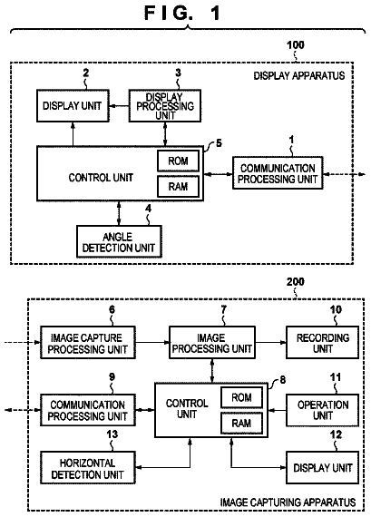
FIG. 1 is a schematic diagram of an image capturing apparatus.
FIG. 2 is a flowchart of a micro adjustment support (MAS) mode of an image capturing apparatus 200 .
FIG. 3 is a diagram illustrating an example of a display screen when the MAS mode occurs a first time.
FIG. 4 is a diagram illustrating an example of a display screen when the MAS mode occurs other than the first time.
FIG. 5 is a flowchart of focus bracket photographing of the image capturing apparatus 200 .
FIG. 6 is a diagram explaining parameters related to the focus bracket photographing.
FIG. 7 is a diagram illustrating a focus detection area (a focus detecting field) of a focus detection apparatus of the image capturing apparatus.
FIGS. 8A and 8B are diagrams illustrating a relationship between the focus detection area and a main subject.
FIG. 9 is a flowchart related to image selection during the focus bracket photographing.
FIGS. 10A and 10B are diagrams illustrating a state in which display areas of bracket-photographed images are displayed side by side.
FIG. 11 is a flowchart of focus bracket photographing according to another embodiment.
Description of the embodiments
Hereinafter, preferred embodiments of the present invention will be described in an exemplary manner. However, the shapes of components described in the embodiments and relative arrangements of the components should be appropriately changed according to a configuration and various conditions of an apparatus to which the present invention is applied, and it is not intended to limit the scope of the present invention to the embodiments described below.
First Embodiment
An image capturing apparatus according to a first embodiment will be described with reference to FIGS. 1 to 10 . Here, a lens interchangeable type single-lens reflex (SLR) camera of phase-different AF method is illustrated as an example of the image capturing apparatus. In the phase-different AF method, a pair of subject images (two image signals having different parallaxes respectively), which are formed after passing through different positions of a photographing lens of a camera, are formed on a line sensor. These subject images are photoelectrically converted into a pair of subject image signals and a difference between the two images is obtained, so that the amount of defocus that indicates a focus adjustment state of the photographing lens to the subject is detected and the photographing lens is driven based on the amount of defocus. It is possible to apply the image capturing apparatus to a camera of imaging plane phase-different AF method and a camera of contrast AF system. Further, it is possible to apply the image capturing apparatus not only to a lens interchangeable type single-lens reflex camera, but also to other image capturing apparatuses such as a mirrorless single-lens reflex camera.
Description of Image Capturing Apparatus
First, a configuration of the image capturing apparatus will be described with reference to FIG. 1 . FIG. 1 is a block diagram illustrating a configuration of the image capturing apparatus 200 according to a first embodiment. As illustrated in FIG. 1 , a photographing lens 100 is detachably attached to the image capturing apparatus 200 through a lens attachment mechanism of a mount unit (not illustrated in FIG. 1 ). An electrical contact unit 104 is provided to the mount unit. The image capturing apparatus 200 communicates with the photographing lens 100 through the electrical contact unit 104 and controls a focus lens 101 (focus lens unit) and a diaphragm (not illustrated in FIG. 1 ) in the photographing lens 100 . In FIG. 1 , only the focus lens 101 is illustrated as a lens unit in the photographing lens 100 . However, a photographing lens in which a plurality of lenses including a variable power lens and a fixed lens are provided in addition to a focus lens is generally used.
A light flux (not illustrated in FIG. 1 ) from a subject is guided to a main mirror 201 in the image capturing apparatus 200 through the focus lens 101 in the photographing lens 100 . The main mirror 201 is arranged obliquely with respect to an optical axis in a photographing optical path and can move to a first position (the position where the main mirror 201 is illustrated in FIG. 1 ) at which the light flux from the subject is guided to a finder optical system above the main mirror 201 and a second position to which the main mirror 201 retracts (moves) out of the photographing optical path.
The entire main mirror 201 is a half mirror. When the main mirror 201 is located at the first position, part of the light flux from the subject passes through the main mirror 201 and part is guided as described above. The light flux that passes through the main mirror 201 is reflected by a sub-mirror 202 arranged in rear of the main mirror 201 and guided to a focus detection apparatus 207 that detects a focus state (the defocus amount of the focus). The focus detection apparatus 207 includes a focus detection sensor (not illustrated in FIG. 1 ) as a photoelectric conversion unit. A CPU 210 (a focus detection unit) detects the defocus amount of the focus by using a signal acquired from the focus detection sensor. In the present embodiment, the focus detection sensor may be implemented by a cross-line sensor.
On the other hand, the light flux reflected on the main mirror 201 forms an image on a focusing screen 203 arranged at a position optically conjugate with the image capturing element 209 . Light (a subject image) which is diffused by the focusing screen 203 and which passes through the focusing screen 203 is converted into an erected image by a pentagonal roof prism 204 . The erected image is enlarged by an eye piece lens 205 and is observed by a user.
When the main mirror 201 retreats to the second position, the sub-mirror 202 also retreats to out of the photographing optical path in a state in which the sub-mirror 202 is folded with respect to the main mirror 201 . In this state, the light flux from the photographing lens 100 passes through a focal plane shutter 208 , which is a mechanical shutter, and reaches the image capturing element 209 . The focal plane shutter 208 limits the amount of light entering the image capturing element 209 . The image capturing element 209 consists of a photoelectric conversion element such as a charge coupled device (CCD) sensor and a complementary metal oxide semiconductor (CMOS) sensor and generates an image by photoelectrically converting the subject image, which is an optical signal formed by the photographing lens 100 , into an electrical signal. The CPU 210 provided in the image capturing apparatus 200 is a controller that controls the entire image capturing apparatus by performing controls and the like of various calculations and various operations in a camera.
The CPU 210 consists of a central processing unit (CPU), a micro processing unit (MPU), and the like. The CPU 210 communicates with a lens control circuit 103 in the photographing lens 100 through the electrical contact unit 104 . The lens control circuit 103 (control unit) controls a lens driving mechanism 102 that performs focusing by driving the focus lens 101 in an optical axis direction according to a signal from the CPU 210 . The lens driving mechanism 102 has a stepping motor as a drive source. A diaphragm control circuit not illustrated in FIG. 1 controls a diaphragm drive mechanism that drives the diaphragm not illustrated in FIG. 1 and adjusts the amount of light flux incident on the image capturing element based on a control signal of the lens control circuit 103 in the photographing lens 100 according to a signal from the CPU 210 .
Further, an electrically erasable programmable read-only memory (EEPROM) 211 used as a memory is connected to the CPU 210 .
In the EEPROM 211 , parameters that are required to be adjusted to control the image capturing apparatus 200 and camera ID information that is unique information to identify the image capturing apparatus are recorded. Further, in the EEPROM 211 , adjustment values of parameters related to photographing, which are adjusted by using a reference lens (a photographing lens used when adjusting the image capturing apparatus in a factory), are recorded. In the present embodiment, the photographing is to acquire an image. Further, an operation detection unit 213 that reflects user's operation to the image capturing apparatus 200 and a counter 214 are connected to the CPU 210 . The counter 214 counts the number of times when the image capturing apparatus performs image capturing.
A display apparatus 212 is an apparatus that displays image data captured by the image capturing element 209 and an item that is set by a user. The display apparatus 212 is generally formed by a color liquid crystal display element.
The operation detection unit 213 detects an operation of a release button and a selection button which are not illustrated in FIG. 1 and a button that causes a user to select one of a plurality of images obtained by bracket photographing described later.
On the other hand, the lens control circuit 103 is provided with a memory (not illustrated in FIG. 1 ) that stores performance information such as a focal length and an open diaphragm value of the photographing lens 100 , lens ID information to identify the photographing lens 100 , and information received from the CPU 210 by communication. The performance information and the lens ID information are transmitted to the CPU 210 by initial communication performed when the photographing lens 100 is attached to the image capturing apparatus 200 , and the CPU 210 stores the performance information and the lens ID information in the EEPROM 211 .
AF Micro Adjustment Support (MAS) Mode
The image capturing apparatus according to the present embodiment has an AF micro adjustment function. The AF micro adjustment function is a system in which a user itself sets a correction amount (or a correction value based on the correction amount) by determining the defocus amount of a value detected by the focus detection apparatus 207 and the direction of the deviation based on an image photographed by the user. The image capturing apparatus 200 according to the present embodiment has an AF micro adjustment support (hereinafter referred to as MAS) mode. In the MAS mode, according to the first embodiment, a difference (an AF correction amount) between a lens position when an image selected is photographed and a lens position after the AF is stored in association with a bracket image. The AF correction amount is utilized as a correction amount (a numerical value displayed according to a scale in FIG. 4 described later) in the AF micro adjustment function.
FIG. 2 is a flowchart of the MAS mode, according to the first embodiment. In step S 001 , it is determined whether or not a user selects the MAS mode. When it is determined that the MAS mode is selected, the process proceeds to step S 002 .
In step S 002 , the operation detection unit 213 verifies whether or not the release button is pressed down by the user. When it is verified that the release button is pressed down, the process proceeds to step S 003 . Step S 002 is repeatedly performed until it is verified that the release button is pressed down.
In step S 003 , an AF operation is performed. The focus detection apparatus 207 detects a defocus amount and drives the focus lens 101 according to the detected defocus amount. At this time, when data of the AF correction amount is obtained by MAS performed in advance, the following equation is established. Lens drive amount=focus detection result (defocus amount)+adjustment value (defocus amount adjustment data at manufacturing)+AF correction amount (MAS data)
When the drive of the focus lens 101 is completed, the process proceeds to step S 004 . In the present embodiment, along with the AF operation in S 003 , the CPU 210 (selection unit) selects a focus detection area used when the bracket photographing described later is performed. The selection of the focus detection area will be described later. Although the focus state is automatically adjusted by the AF operation in the present embodiment, the focus state may be manually adjusted.
In step S 004 , the CPU 210 (calculation unit) calculates an AF reliability evaluation value of a subject based on a signal received by the focus detection sensor (not illustrated) included in the focus detection apparatus 207 . When the subject is dark (brightness is low) or contrast is low, focus detection accuracy of the focus detection apparatus 207 may degrade. A calculation formula is formed so that the AF reliability evaluation value is low when a subject where the focus detection accuracy of the subject is degraded is used. When the AF reliability evaluation value has been calculated, the process proceeds to step S 005 .
In step S 005 , whether or not MAS mode is possible is determined based on the AF reliability evaluation value calculated in step S 004 . When the AF reliability evaluation value is high, that is, when it is determined that the MAS mode is possible, the process proceeds to step S 008 , and when the AF reliability evaluation value is low, that is, when it is determined that the MAS mode is not possible, the process proceeds to step S 006 . The AF reliability evaluation value is calculated from a plurality of viewpoints, so that there is a plurality of AF reliability evaluation values. (As described above, there is a plurality of viewpoints such as brightness of the subject and contrast of the subject) In this case, it is possible to determine whether or not the MAS mode is possible based on whether or not all the AF reliability evaluation values are satisfied or based on an AF reliability evaluation value at a predetermined viewpoint.
In step S 006 , the display apparatus 212 notifies the user that a focus detection target subject is inappropriate for the MAS. When the notification is completed, the process proceeds to step S 007 .
In step S 007 , the user determines whether or not to perform the MAS again. A display to cause the user to determine whether or not to perform the MAS again is displayed on the display apparatus 212 , and the user determines whether or not to perform the MAS again by operating operation buttons. The operation detection unit 213 detects the determination whether or not the user performs the MAS again by operating operation buttons, and when it is determined that the user performs the MAS again, the process returns to step S 002 . On the other hand, when it is determined that the user does not perform the MAS again, the process proceeds to step S 012 and the MAS mode is completed.
In step S 008 , information of the subject is detected. Spatial frequency information of the subject is detected based on a signal received by the focus detection sensor (not illustrated) included in the focus detection apparatus 207 . Regarding the detected spatial frequency information, a subject information flag which is a value digitized based on a condition that is set in the image capturing apparatus 200 in advance is stored in the EEPROM (memory) 211 . In the present embodiment, when the spatial frequency information is higher than a set threshold value, the subject information flag is stored as 0, and when the spatial frequency information is lower than the set threshold value, the subject information flag is stored as 1. The detection of the subject information in this step is not limited to a case in which the focus detection sensor included in the focus detection apparatus 207 is used, but a subject detection sensor that is generally arranged in a finder and the image capturing element 209 may also be used. The subject information flag is set not only according to the spatial frequency information, but it may also be set according to the magnitude of edge information (an integrated value of difference between adjacent pixel values or the like) of a main subject (a subject to be focused). When the detection of the subject information is completed, the process proceeds to step S 009 .
In step S 009 , the focus bracket photographing is performed. When the focus bracket photographing is completed, the process proceeds to step S 010 .
In step S 010 , the CPU 210 selects an image that is in the best focusing state from among images which the CPU 210 has photographed by the focus bracket photographing in step S 009 . The selection of the image will be described later.
When the selection of the image is completed, the process proceeds to step S 011 .
In step S 011 , a correction value is stored. The correction value is determined based on an AF correction amount corresponding to a lens position associated with an image selected by the user. When there is a plurality of images selected in step S 010 , a correction value corresponding to an average value of lens positions associated with the selected images is determined. The determined correction value is stored in the EEPROM (memory) 211 . The stored correction value is notified to the user. FIG. 3 is a diagram illustrating an example of a screen on which the display apparatus 212 displays a correction value stored by MAS at this time when the MAS is the first time. FIG. 4 is a diagram illustrating an example of a screen on which the display apparatus 212 displays a stored correction value when the MAS at this time is not the first time and there is a correction value stored by a previous MAS. In FIG. 4 , the white triangle represents the previous correction value and the black triangle represents a new correction value stored by a flow at this time. By performing a display illustrated in FIG. 4 , the user can verify the stored correction value. When the correction value has been stored, the process proceeds to step S 012 and the MAS mode is completed.
Selection of Focus Detection Area
Hereinafter, selection of a focus detection area which is used for AF processing in the bracket photographing will be described. FIG. 7 illustrates the focus detection area corresponding to the focus detection sensor of the focus detection apparatus of the image capturing apparatus of the present embodiment. Although other focus detection areas are omitted for simplicity of description, an image capturing apparatus including a plurality of focus detection areas is commonly used.
In FIG. 7 , an image capturing area 500 is an area where a subject image is acquired by an image capturing element. Focus detection areas 501 and 502 are areas where the focus detection apparatus 207 detects a focus state. Each of the focus detection areas 501 and 502 corresponds to a partial area of the image capturing area. In the present embodiment, the focus detection areas 501 and 502 are arranged in a vertical direction and a horizontal direction respectively. The focus detection area 501 is a detection area corresponding to pixels arranged in a horizontal direction in a line sensor included in the focus detection apparatus 207 . The line sensor detects a vertical line component of a main subject which is a subject to be focused in a range corresponding to the focus detection area 501 . The focus detection area 502 is a detection area corresponding to pixels arranged in a vertical direction in a line sensor included in the focus detection apparatus 207 . The line sensor detects a horizontal line component of the main subject in a range corresponding to the focus detection area 502 . During photographing, the CPU 210 selects an optimal focus detection area from among the focus detection areas 501 and 502 according to the main subject.
FIGS. 8A and 8B are diagrams illustrating a relationship between the focus detection area and the main subject. As an example of the main subject, a black line pattern 510 that is a long pattern in the vertical direction or a black line pattern 520 that is a long pattern in the horizontal direction is projected to the focus detection area 501 and the focus detection area 502 .
FIG. 8A illustrates a situation intending to capture an image of the main subject in which a vertical line component is dominant. When intending to detect the long black line pattern 510 as the main subject in which the vertical line component is dominant, in the focus detection area 501 in which the vertical line component is detected, the black line pattern 510 which is long in the vertical direction overlaps only a central portion of the entire focus detection area 501 . On the other hand, in the focus detection area 502 in which the horizontal line component is detected, the black line pattern 510 overlaps the entire focus detection area 502 . Therefore, it is possible to detect a pattern in the focus detection area 501 . However, it is difficult to detect a pattern in the focus detection area 502 because only a uniform image can be obtained from the black line pattern 510 in the focus detection area 502 . In this case, the focus detection area 501 is selected as the focus detection area during photographing. In the present embodiment, the CPU 210 (selection unit) selects the focus detection area 501 when the vertical line component is greater than the horizontal line component by a predetermined ratio.
FIG. 8B illustrates a situation intending to capture an image of the main subject in which a horizontal line component is dominant. In the focus detection area 501 , the black line pattern 520 which is the main subject in which the horizontal line component is dominant overlaps the entire focus detection area 501 . On the other hand, in the focus detection area 502 , the black line pattern 520 overlaps only the central portion of the entire focus detection area 502 . Therefore, it is possible to detect a pattern in the focus detection area 502 . However, it is difficult to detect a pattern in the focus detection area 501 because only a uniform image is obtained from the black line pattern 520 in the focus detection area 501 . In this case, the focus detection area 502 is selected as the focus detection area during photographing. In the present embodiment, the CPU 210 selects the focus detection area 502 when the horizontal line component is greater than the vertical line component by a predetermined ratio.
Although FIGS. 8A and 8B illustrate an example of the black line pattern for easy understanding of the selection of the focus detection area, even when a pattern can be detected from both the focus detection areas 501 and 502 , a focus detection area from which the pattern can be better detected is selected. In other words, when there is not a large difference between ratios of the vertical line component and the horizontal line component (when the difference is smaller than a predetermined ratio), a focus detection area from which the pattern can be better detected is selected. At this time, there may be an index for selecting the focus detection area in addition to the ratios of the vertical line component and the horizontal line component described in the present embodiment. In this case, the CPU 210 (calculation unit) calculates evaluation values for at least one index and selects a focus detection area of which evaluation value is the highest. For example, from among the focus detection areas 501 and 502 , a focus detection area of which AF reliability evaluation value calculated in step S 004 is higher may be selected. Although a configuration in which the focus detection area is automatically selected is illustrated in the present embodiment, it may be configured so that a user can select a focus detection area to be used in advance.
Focus Bracket Photographing
The image capturing apparatus according to the present embodiment has a function to perform the focus bracket photographing. The focus bracket photographing is a photographing method that sequentially acquires a plurality of images while changing a focus by every predetermined amount. FIG. 5 is a flowchart of the focus bracket photographing performed by the image capturing apparatus 200 of the first embodiment.
In step S 101 , parameters related to the focus bracket photographing are determined. The parameters are the number of images to be obtained by the focus bracket photographing and a photographing position of the focus lens 101 in the focus bracket photographing. FIG. 6 is a diagram explaining the parameters related to the focus bracket photographing. In FIG. 6 , the position of “lens position=0” is a position after AF, where the focus lens 101 is driven by the AF operation and then stops and which is the center position of the focus lens 101 in the bracket photographing. The focus lens 101 is driven to a position according to a count value of the counter 214 . The parameters related to the focus bracket photographing are determined based on a value stored in step S 008 in the flowchart illustrated in FIG. 2 . When the subject information flag is 0, the number of photographed images m=7 is established, and when the subject information flag is 1, the number of photographed images m=9 is established. In general, the higher the spatial frequency of the subject, the easier the determination of the focusing state, so that the number of photographed images may be small.
The driving amount is an amount (kP) obtained by multiplying a correction interval P of the AF micro adjustment described above by a coefficient k (the coefficient k is an integer value greater than or equal to 2). In the present embodiment, when the subject information flag is 0, the coefficient k=2 is established, and when the subject information flag is 1, the coefficient k=4 is established. In general, the higher the spatial frequency of the subject, the easier the determination of the focusing state, so that it is possible to perform the determination even when the driving amount of the focus lens 101 is small. This is the same when the subject information is edge information, so that each parameter may be set according to how easy the determination of the focusing state of the subject is.
The parameters related to the focus bracket photographing may be arbitrarily determined by a user. It is possible to build a system suitable for the user by using parameters variable according to a level of the user. Although the number of photographed images and the driving amount, which are the parameters of the focus bracket photographing, are variables in the present embodiment, either one or both of them may be a fixed value or fixed values of the image capturing apparatus 200 and the photographing lens 100 .
In step S 102 , the CPU 210 resets the counter 214 (the count value n=0 is established). When the counter has been reset, the process proceeds to step S 103 .
In step S 103 , a mirror up operation is performed in which the main mirror 201 retreats to the second position outside the photographing optical path and the sub-mirror 202 also retreats along with the main mirror 201 .
After the mirror up operation is completed, in step S 104 , the focus lens 101 is driven. As described with reference to FIG. 6 , when the count value n=1, the focus lens 101 moves to a position of −(m−1)/2×kP. When the count value n≥2, the focus lens 101 moves from a position at which the focus lens 101 stops toward the infinity side by +kP. In other words, the focus lens 101 moves to a position of −(m+1−2n)/2×kP according to the count value. When the drive of the focus lens 101 is completed, the process proceeds to step S 105 .
In step S 105 , still image photographing is performed. A photographed image is stored in an internal memory of the CPU 210 in association with a lens position when the image is photographed. When the photographed image has been recorded, the process proceeds to step S 106 .
In step S 106 , the count value of the counter 214 is incremented by one, and the process proceeds to step S 107 .
In step S 107 , it is determined whether or not the count value of the counter 214 reaches the number of photographed images m. When the count value reaches the number of photographed images m, the process proceeds to step S 108 , and when the count value does not reach the number of photographed images m, the process returns to step S 104 .
In step S 108 , a mirror down operation is performed in which the main mirror 201 moves to the first position and the sub-mirror 202 moves to a position inside the photographing optical path. Then, the process proceeds to step S 109 and the focus bracket photographing is completed.
Image Selection after Focus Bracket Photographing
FIG. 9 is a flowchart related to image selection after the focus bracket photographing.
When image selection processing is started, in S 1000 , the focus detection area (the focus detecting field) which is selected and actually used during the focus bracket photographing is determined.
In S 1010 , the CPU 210 (display unit) performs processing that sets a part of each bracket image obtained by the focus bracket photographing as a display area for each part. The display area is set so as to include the focus detection area determined in S 1000 . When, like the focus detection area 501 , the determined focus detection area is a detection area corresponding to pixels arranged in the horizontal direction in the line sensor included in the focus detection apparatus 207 , the display area is set to be long in the horizontal direction. Similarly, when, like the focus detection area 502 , the determined focus detection area is a detection area corresponding to pixels arranged in the vertical direction in the line sensor included in the focus detection apparatus 207 , the display area is set to be long in the vertical direction. For example, referring to FIGS. 8A and 8B described above, in the present embodiment, when the CPU 210 (selection unit) selects the focus detection area 501 during photographing, the CPU 210 (display unit) selects a display area 503 , and when the CPU 210 (selection unit) selects the focus detection area 502 during photographing, the CPU 210 (display unit) selects a display area 504 . However, the display areas 503 and 504 are an example, and their sizes and aspect ratios are not intended to be limited.
The display areas of the bracket images are adjusted so that edges of the main subject are evenly arranged when the display areas are displayed side by side. This adjustment may be performed by extracting feature points of each image and performing image processing or may be performed based on shake information of the image capturing apparatus. By displaying the display areas in this way, it is easy for a user to compare differences between the images.
In S 1030 , a display image to be actually displayed by the display apparatus 212 is generated based on the display area of each bracket image that is set in S 1010 . Specifically, one image is generated in which images of a selected area of each bracket image that is set in S 1010 are arranged in order of each bracket image. At this time, the arrangement direction of each display area is a direction perpendicular to a pixel arrangement of the focus detection area selected when the photographing is performed. In other words, for example, when the display area 503 that is long in the horizontal direction (a direction based on a horizontal line) is selected as a display area, a display area that is long in the horizontal direction is selected for the other bracket images. A display image in which these display areas are arranged side by side in a vertical direction (a direction based on a vertical line) as illustrated in FIG. 10A is generated. Further, for example, when the display area 504 that is long in the vertical direction (a direction based on a vertical line) is selected as a display area, a display area that is long in the vertical direction is selected for the other bracket images. A display image in which these display areas are arranged side by side in a horizontal direction (a direction based on a horizontal line) as illustrated in FIG. 10B is generated.
In S 1040 , the CPU 210 (display unit) displays the display image generated from the bracket images.
Each of FIGS. 10A and 10B illustrates a case in which the bracket photographing of nine images is performed and further illustrates a case in which the best focused image is located at the center, that is, the fifth image. The width and focus state of a black line pattern vary according to the focus state of the bracket image. Although the details will be described later, the width (the size) of the subject image varies according to a change of image magnification ratio due to a focusing operation and a blur of image due to a change of the focus. However, an image in the best focusing state is seen to be thinnest, so that the fifth line at the center is thinnest.
While a state in which the fifth image is best focused is illustrated here, there may be a case in which a display image, in which an endmost image is best focused, that is, the width of the endmost image is smallest, is generated and displayed depending on an actual state of the image capturing apparatus.
In this way, an image is displayed in which attention areas to be focused in the bracket images are arranged in one image generated in S 1030 , so that it is easy for a user to compare images with each other.
At this time, regarding the image to be displayed, an image on which processing such as edge enhancement processing is not performed can be displayed in order to cause the user to easily know the focus state. When the image has been displayed, the process proceeds to the next step S 1050 .
In S 1050 , it is determined whether or not a change operation of display scale of the displayed image is performed.
When it is determined that the change operation of display scale is not performed in S 1050 , the process proceeds to the next step S 1070 . When it is determined that the change operation of display scale is performed, the process proceeds to the next step S 1060 .
In S 1060 , display scale is changed according to the scale that is set by the user, and the process proceeds to S 1010 again in order to generate a display image where a display area of scale that is set by the user. Then, in S 1010 , a display image scale is changed, and setting of the display area of the bracket image is performed again. Here, the change of the scale of the display area in S 1060 can be performed in conjunction with that of the display areas of all the bracket images. By such a configuration, it is possible to compare the display areas of all the bracket images at the same scale, so that it is easy to compare the display areas. Based on the setting in S 1010 described above, the display image is generated again in S 1030 and the display image is displayed in S 1040 .
In S 1070 , it is determined whether or not the display area of the display image is changed.
In S 1070 , when it is determined that the display area is not changed, the process proceeds to the next step S 1090 . In S 1070 , when it is determined that the display area is changed, the process proceeds to the next step S 1080 .
The description continues in the full USPTO document.
 Lapsed, fee not paid12 drawings

