 Lapsed, fee not paid12 drawings
Hardware & Electronics · US 9,922,479 B2
Task enabled switch system
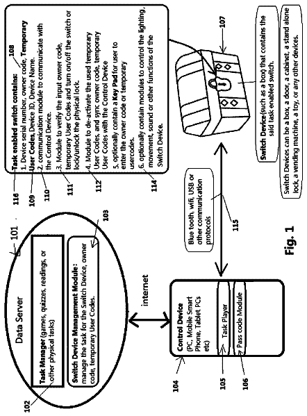
A Task Enabled Switch System comprising: A Data Server with a Task Manager Module and a Switch Device Management Module;
US 9,922,552 B2 · Assignee: PANASONIC INTELLECTUAL PROPERTY CORPORATION OF AMERICA · Inventors: Amano; Katsushige et al.
Sheet 1 of 19 from the published document. All sheets in the USPTO PDF
A first control apparatus receives a device control log of a second control apparatus, and stores a shared log that results from adding the received device control log of the second control apparatus to a device control log of the first control apparatus. Upon acquiring a control request from a user to control the device, the first control apparatus determines based on the shared log whether the device is ready for control. If the device is determined to be ready, the first control apparatus transmits to the device a control command responsive to the acquired control request.
Techniques of using remote controllers to remote control home electronics at home via a network are available.
1 of 19 drawing sheets so far from the published document, cropped to the drawing. Every sheet is in the USPTO PDF.
What the patent claimed, word for word. All of it is now free to use.
The present disclosure relates to a control apparatus that controls a device and a control method of the control apparatus.
Techniques of using remote controllers to remote control home electronics at home via a network are available.
One non-limiting and exemplary embodiment provides further improvements in related-art remote control technique.
In one general aspect, the techniques disclosed here feature a method of controlling a device connected to a network that is connected to a first control apparatus and a second control apparatus different from the first control apparatus. The method includes receiving from the second control apparatus a device control log of the second control apparatus, adding the received device control log of the second control apparatus to a device control log of the first control apparatus to obtain a shared log, storing the shared log, acquiring a control request of a user to the device, determining whether the device is ready for control responsive to the acquired control request based on the shared log, and transmitting to the device a control command responsive to the acquired control request if the device is determined to be ready.
In accordance with the disclosure, the device is appropriately controlled in a manner free from contention in control of each controller even if multiple controllers are used.
It should be noted that general or specific embodiments may be implemented as a system, a method, an integrated circuit, a computer program, a storage medium, or any selective combination thereof.
Additional benefits and advantages of the disclosed embodiments will become apparent from the specification and drawings. The benefits and/or advantages may be individually obtained by the various embodiments and features of the specification and drawings, which need not all be provided in order to obtain one or more of such benefits and/or advantages.
FIG. 1 illustrates an example of an entire configuration of a device control system installed in a home including a control apparatus of an embodiment of the disclosure;
FIG. 2A illustrates an example of a hardware configuration of a controller body, and a user terminal;
FIG. 2B illustrates another example of the hardware configuration of the controller body, and the user terminal;
FIG. 3 illustrates an example of a shared log recorded in a log memory;
FIG. 4A illustrates an example of a device control screen that a user uses to enter a control request;
FIG. 4B illustrates another example of the device control screen that the user uses to enter the control request;
FIG. 4C illustrates another example of the device control screen that the user uses to enter the control request;
FIG. 5 illustrates a configuration example of a controller of a first embodiment;
FIG. 6 illustrates an entire configuration of a device control system of the first embodiment;
FIG. 7 illustrates an example of a control time interval table;
FIG. 8A is a flowchart illustrating a process routine of the controller of the first embodiment;
FIG. 8B is a flowchart illustrating a process routine of the controller of the first embodiment;
FIG. 9A illustrates a display example of the device control screen of the first embodiment;
FIG. 9B illustrates a display example of the device control screen that displays the controller of the first embodiment separately from an ordinary controller;
FIG. 10 illustrates a configuration example of a controller of a second embodiment;
FIG. 11 illustrates an example of an entire configuration of a device control system of the second embodiment;
FIG. 12A is a flowchart illustrating a process routine of the controller of the second embodiment;
FIG. 12B is a flowchart illustrating a process routine of the controller of the second embodiment; and
FIG. 12C is a flowchart illustrating a process routine of the controller of the second embodiment.
Underlying Knowledge Forming Basis of the Present Disclosure
Techniques of using remote controllers to remote control home electronics at home via a network are available. Remote controlling that permits a short duration of time between a current control operation and an immediately preceding operation may occasionally suffer from inconvenience. For example, a device may take time to start up, and receive no control operation before being fully started up. Another device could be damaged if consecutive control operations are input for a short duration of time. Another device to be controlled needs a predetermined duration of time from one control operation to a next control operation because of device throughput thereof.
A user may use a controller to remote control a device, and may acquire status information of the device to confirm that the device is in a user's desired state. Also, the user may be confused with the state of the device that may be caused by an operation by another user before or after the current operation.
Such a problem may be cleared in this way. The controller may store a log of a control operation performed by the controller, references the log, and indicate to the user that a control operation to the device is currently denied. Alternatively, the controller may hold a control request in suspension for the time being, and perform a control operation on the device after an elapse of an appropriate time period.
Japanese Unexamined Patent Application Publication No. 2014-216945 discloses a remote control technique. In the disclosed technique, a user is requested to decide and instruct a control operation to perform in view of safety information. For example, if control operations contending with each other are to be performed during a predetermined period of time, a request to decide and instruct which control operation to be performed is issued to the user.
There may be multiple controllers at home. For example, television receivers (TVs) having a function of controller may be respectively installed in multiple rooms. A user may operate a TV in each room to control a device. In such a case, the single device is controlled by the multiple TVs.
Japanese Unexamined Patent Application Publication No. 2001-346276 discloses a technique of solving the problems of damage or deadlock caused by concurrent control by multiple controllers. In the disclosed technique, device control systems are prioritized to limit concurrent control of a device by multiple controllers. International Publication No. WO2010/119540 discloses a control technique. In the disclosed technique, each controller periodically creates a controller list that indicates which controller has controlled the device last in order to determine which of multiple controllers is permitted to control the device. A controller currently attempting to control the device determines that the device is currently controlled by another controller if the controller list indicates that the device has been controlled in the latest control operation by the other controller. The controller thus asks the other controller whether the controller is permitted to control the device.
If there are multiple controllers in a home, the device may receive control requests from multiple controllers during a predetermined period of time. Even if the controllers successively control the device in accordance with a device control log stored therein, an appropriate period of time may not necessarily be taken. From the safety point of view or legal point of view, the device desirably responds to control requests with a predetermined duration of time taken therebetween.
According to Japanese Unexamined Patent Application Publication No. 2014-216945, the device is controlled by referencing the log, but the control operation is based on the premise that the device is controlled by a single controller. If multiple controllers cause contention in the control operation, the device is difficult to control appropriately.
According to Japanese Unexamined Patent Application Publication No. 2001-346276, one control instruction is selected to control the device as a control target in accordance with the predetermined priority if a control command from a remote controller contents with a control command from a network interface. The device is thus controlled. The control commands are selected in accordance with not the device control log but the predetermined priority.
According to International Publication No. WO2010/119540, the controller list is periodically generated. A device that has been controlled by none of the controllers may be controlled by a given controller immediately subsequent to the generation of the controller list. In such a case, the information concerning that device is not reflected in the controller list. Control contention to the device is difficult to avoid.
In view of the above background, the inventors have reached embodiments of the disclosure.
According to a first aspect of the disclosure, there is provided a method of controlling a device connected to a network that is connected to a first control apparatus and a second control apparatus different from the first control apparatus.
The control method includes:
receiving from the second control apparatus a device control log of the second control apparatus;
adding the received device control log of the second control apparatus to a device control log of the first control apparatus to obtain a shared log;
storing the shared log;
acquiring a control request of a user to the device;
determining whether the device is ready for control responsive to the acquired control request based on the shared log; and
transmitting to the device a control command responsive to the acquired control request if the device is determined to be ready.
According to the first aspect, the first control apparatus receives the device control log from the other control apparatus when the other control apparatus controls the device. The first control apparatus stores the shared log that is the sum of the device control log thereof and the received device control log. The first control apparatus may learn which control apparatus currently controls the device by referencing the shared log, and thus controls the device in a manner free from contention.
According to a second aspect; in the determining; the device is determined to be ready if a predetermined time period elapses since the device is controlled last.
According to the second aspect, the device having received the control request serving as a control target is determined to be controllable if the predetermined period of time has elapsed since the last control operation of the device. The device is thus controlled after the elapse of the predetermined period of time. For this reason, this operation practice follows regulations that the device should be controlled with a predetermined time interval inserted between control operations and causes the device to operate safely.
According to a third aspect, displaying information, indicating that the device is not ready, on a display of the first control apparatus or a display device connected to the first control apparatus via the network if the device is determined to be not ready.
According to the third aspect, the user is notified that the control operation of the device is denied if the first control apparatus determines that the first control apparatus is denied to control the device. The user thus learns that the device is uncontrollable currently. This arrangement avoids inputting of a control request by the user at an inappropriate timing.
According to a fourth aspect, displaying a remaining time until the device is ready.
According to the fourth aspect, the period of time before the first control apparatus is permitted to control the device is displayed. This arrangement reduces the user's annoyance caused by the control operation denial. This arrangement also avoids inputting of a control request by the user during a control denial period, and reduces a process load that is expected to be caused as a result of receiving the control request during this period.
According to a fifth embodiment, displaying information prompting a user to input a response to an enquiry as to whether the device is to be controlled in an automatic manner in response to the acquired control request when the device becomes ready,
wherein in the transmitting, the control command is transmitted to the device after the remaining time elapses in response to the input response to control the device in the automatic manner.
According to the fifth aspect, the control command is automatically transmitted in response to the input control request after the elapse of the time period to the control operation permit. This arrangement reduces time to re-enter the control request. The user is allowed to select whether to automatically transmit the control command responsive to the control request.
According to a sixth aspect, displaying a current status of the device.
According to the sixth aspect, the current status of the device is displayed if the first control apparatus determines that the first control apparatus is denied to control the device. The user is thus provided with information for determining whether to control the device.
According to a seventh aspect, detecting a control apparatus that is different in type and function from the first control apparatus, using information contained in communication data transmitted from the different control apparatus; and
displaying information, indicating that the different control apparatus is present, on a display of the first control apparatus or a display device connected to the first control apparatus via the network if the different control apparatus has been detected.
According to the seventh aspect, if the control apparatus that is different in type and function from the first control apparatus is detected, the user is also notified of the detection. The user is aware that the different type of the control apparatus is present over the network.
According to an eighth aspect, transmitting information related to the control command to the second control apparatus if the control command has been transmitted in the transmitting.
Since the first control apparatus transmits the information related to the control command to the other control apparatus in the eighth aspect, the first control apparatus shares the device control log of the first control apparatus with the other control apparatus.
According to a ninth aspect, there is provided a method of controlling a device connected to a network that is connected to a first control apparatus and a second control apparatus different from the first control apparatus.
The method of the second control apparatus includes
receiving from the second control apparatus a control request of a user to the device input in the second control apparatus;
adding the received control request serving as a device control log of the second control apparatus to a device control log of the first control apparatus to obtain a shared log;
storing the shared log;
determining whether the device is ready for control responsive to the received control request based on the shared log; and
transmitting to the device a control command responsive to the received control request if the device is determined to be ready.
According to the ninth aspect, the control request is transmitted to the first control apparatus when the user inputs the control request on the second control apparatus. Upon receiving the control request, the first control apparatus adds the received control request as the device control log of the second control apparatus to the device control log thereof to generate the shared log, and then stores the shared log. By referencing the shared log, the first control apparatus learns which control apparatus currently controls the device, and thus controls the device in a manner free from contention. Since the first control apparatus transmits the control command to the device after the control request input to the second control apparatus is transmitted to the first control apparatus, it is sufficient if the first control apparatus stores the shared long. The other control apparatuses are free from storing the shared log.
According to a tenth aspect, the method may include displaying information, indicating that the device is ready, on a display of the second control apparatus or a first display device connected to the second control apparatus via the network if the device is determined to be ready; and
displaying information, indicating that the device is not ready, on a third control apparatus different from the first control apparatus and the second control apparatus or on a second display device connected to the third control apparatus via the network.
According to the tenth aspect, the display of the second control apparatus or the display device connected to the second control apparatus via the network displays the information that the control operation of the device is permitted if the second control apparatus is permitted to control the device. The user of the second control apparatus is thus notified that the control operation to the device is permitted.
On the other hand, the control apparatus other than the second control apparatus or the display device connected to the control apparatus other than the second control apparatus via the network displays the information that the control operation to the device is denied. The user of the control apparatus other than the second control apparatus is notified that the control operation to the device is denied.
The disclosure not only provides the control method to perform the characteristic process described above but also provides a control apparatus configured to execute characteristic steps included in the control method. The disclosure also provides a computer program configured to cause a computer to execute the characteristic steps included in the control method. The computer program may also be distributed via a non-transitory computer readable medium, such as a compact-disk read-only memory (CD-ROM), or a communication network, such as the Internet.
Each of the embodiments described below represents a specific example of the disclosure. Numerical values, shapes, elements, steps and the order of the steps in the embodiments are described for exemplary purposes only, and are not intended to limit the disclosure. Elements not described in independent claims indicative of a generic concept, from among the elements of the embodiments, may be any elements. Contents of the embodiments may be combined in use.
Entire Configuration
The entire configuration of a device control system including a control apparatus in an embodiment of the disclosure is described below. FIG. 1 illustrates an example of the entire configuration of the device control system installed in a home including a control apparatus of an embodiment of the disclosure. The device control system includes two controllers 1 (an example of a first control apparatus and a second control apparatus), for example. To differentiate one controller 1 from the other controller 1 , the one controller is designated 1 A, and the other controller is designated 1 B. Referring to FIG. 1 , the two controllers 1 are illustrated for example. The device control system may include two or more controllers.
The controller 1 includes a controller body 2 and a user terminal 3 configured to be operated by the user. A network 20 is installed in the home. The network 20 interconnects the controller 1 to a refrigerator 11 , an air-conditioner 12 , and a lighting device 13 that are controlled by the controller 1 . These devices are controlled by receiving a predetermined control command via the network 20 . Referring to FIG. 1 , the devices include home electronics, such as the refrigerator 11 , the air-conditioner 12 , and the lighting device 13 . These devices are illustrated for exemplary purposes only. For example, the home electronics may include a washing machine, a microwave oven, a recorder, or audio equipment. Since the devices are installed in the home as illustrated in FIG. 1 , the devices are referred to as home electronics. If the device control system of the disclosure is applied in an environment, such as in an office, the device is simply referred to as a device.
The user operates the user terminal 3 to perform a control operation on the refrigerator 11 , the air-conditioner 12 , or the lighting device 13 . The control operation herein refers to an on-off operation of the power of the device, a control operation to change a temperature setting of the air-conditioner 12 , or a control operation to change a brightness level of the lighting device 13 . By inputting a control request to control the device onto the user terminal 3 , the user may remote control the device.
The user terminal 3 may be integrated with the controller body 2 in a unitary body, or may be formed as a unit separate from the controller body 2 . If the user terminal 3 is a separate unit, the user terminal 3 simply transmits the control request input by the user to the controller body 2 via the network 20 . The user terminal 3 does not necessarily have to be installed in a home. The user terminal 3 may transmit the control request to the controller 1 from outside the home via an outside network or a server.
The network 20 may be a wired or wireless local area network (LAN) installed in the home. For example, the network 20 may be an IEEE 802.3 series wired LAN or an IEEE 802.11 series wireless LAN, or a combination thereof.
FIGS. 2A and 2B illustrate examples of hardware configuration of the controller body 2 and the user terminal 3 . FIG. 2A illustrates an example of the hardware configuration of the controller 1 in which the controller body 2 is integrated with the user terminal 3 in a unitary body. FIG. 2B illustrates an example of the hardware configuration of the controller 1 in which the controller body 2 and the user terminal 3 are separated from each other.
As illustrated in FIG. 2A , the controller body 2 includes a central processing unit (CPU) 31 , a memory 32 , such as a random-access memory, and an external storage device 33 , such as a hard disk or a flash ROM. In other words, the controller body 2 has the form of a computer. The controller body 2 of FIG. 2A includes a network interface 34 to be connected to the network 20 . The network interface 34 includes a LAN card to connect the controller 1 to the wired LAN, and a communication device to connect the controller 1 to a Wi-Fi wireless communication network.
An input device 35 includes a switch and a keyboard, and an output device 36 is a display device including a display. If the controller 1 includes a touchpanel, the input device 35 and the output device 36 of the user terminal 3 in the form of the touchpanel are integrated with the controller 1 . Referring to FIG. 2A , the controller 1 may be mounted on a device, or on a dedicated communication device, such as a gateway, or on a dedicated apparatus, such as a home server.
As illustrated in FIG. 2B , the user terminal 3 is an information processing apparatus that is separate from the controller body 2 , such as a tablet terminal. The user terminal 3 includes a CPU 31 , a memory 32 , an external storage device 33 , a network interface 34 , an input device 35 , and an output device 36 . The user terminal 3 of FIG. 2B may be a portable information processing apparatus, such as a smart phone. Referring to FIG. 2B , the controller body 2 may be mounted on a device, or on a dedicated communication device, such as a gateway, or on a dedicated apparatus, such as a home server. The user terminal 3 is an example of a “display device connected to the control apparatus via the network”.
Turning to FIG. 1 , the controller body 2 includes a device controller 101 (an example of a request receiver), a control information communication unit 102 (an example of a control information transmitter), a log memory 103 , and a control operation permit determination unit 104 . The user terminal 3 includes an operation unit 201 and a display 202 . The device controller 101 , the control information communication unit 102 , the log memory 103 , and the control operation permit determination unit 104 are implemented when a processor, such as the CPU 31 , executes software programs. But the disclosure is not limited to this arrangement. The device controller 101 , the control information communication unit 102 , the log memory 103 , and the control operation permit determination unit 104 may be implemented using hardware, such as large scale integration (LSI) or a dedicated circuit (such as an application specific integrated circuit (ASIC) or a field programmable gate array (FPGA)).
The operation unit 201 receives a control request the user has input on the input device 35 , and outputs the received control request to the controller body 2 . The display 202 includes the output device 36 ( FIG. 2A and FIG. 2B ), and presents, to the user, information regarding a status of the device notified by the controller body 2 .
Upon receiving the control request from the user via the user terminal 3 , the device controller 101 transmits a control command via the network 20 to honor the control request to a device serving as a control target. In this way, the device is controlled in response to the control request of the user.
The control information communication unit 102 exchanges device control information with the multiple controllers 1 . The device control information indicates which device is controlled in what way.
The log memory 103 stores a shared log that includes a log of a device control operation performed by a first controller 1 and a log of a device control operation performed by a second controller 1 received by the control information communication unit 102 .
FIG. 3 illustrates an example of a shared log T 3 that is recorded by the log memory 103 . The shared log T 3 stores “device ID”, “control time”, “device type”, “model name”, “contents of control operation”, and “user” in association with each other.
The device ID is an identifier uniquely identifying each device at home. The device ID is shared among the multiple controllers 1 at home. More specifically, the same “device ID” represents the same device in any controller 1 . The device ID may be a communication address of the device over the network 20 , or a serial number unique to each device.
The control time represents time when the device is controlled. The shared log T 3 may store, as the control time, at least time when the device was controlled last.
The device type indicates the type of each device, such as an air-conditioner or an illumination device. The model name is a symbol string that is given the device for product classification. The contents of control operation refer to contents of control operation performed on the device. For example, the contents of control operation may be “changing temperature setting” on the air-conditioner 12 , “power on” on the lighting device 13 , “opening the door” or “closing the door” on the refrigerator 11 .
The user indicates a user name of the user who has made a control request on the device. The device control system of FIG. 1 manages user account information in which a user name is associated with a password. The user enters the user name and password to use the device control system, and logs in on the device control system. From the user name entered at the log-in, the device control system identifies the user name of the user who has entered the control request.
Turning to FIG. 1 , the control operation permit determination unit 104 determines in accordance with the shared log T 3 whether the control operation to be performed by the device controller 101 is permitted. More specifically, if the device controller 101 receives the control request to a given device, the control operation permit determination unit 104 acquires from the shared log T 3 the control time of the latest control operation of the device and contents of the control operation. If a predetermined period of time determined by the acquired contents of the control operation has not elapsed since the acquired control time, the control operation permit determination unit 104 determines that the control operation responsive to the control request is denied.
The control operation permit determination unit 104 may calculate a remaining period of time until the control operation is permitted. More specifically, the control operation permit determination unit 104 may calculate the remaining period of time by subtracting the present time from the time resulting from adding a predetermined time interval determined by the acquired contents of the control operation to the control time.
If the predetermined time interval determined by the acquired contents of the control operation has elapsed since the control time acquired from the shared log T 3 , the control operation permit determination unit 104 determines that the control operation responsive to the control request is permitted.
If the control operation permit determination unit 104 determines that the control operation is denied, the control operation permit determination unit 104 does not transmit a control command responsive to the control request. The control operation permit determination unit 104 displays on the display 202 information that the control operation is denied, and the remaining time until the control operation is permitted. In such a case, the control operation permit determination unit 104 holds the control request in suspension until the control operation is permitted. When the control operation is permitted, the control operation permit determination unit 104 automatically transmits the control command. In this way, this arrangement avoids transmitting the control command to the device before the predetermined time interval has elapsed since the last control operation of the device.
FIG. 4A illustrates an example of a device control screen 301 the user uses to enter the control request. The device control screen 301 of FIG. 4A displays a refrigerator icon 311 , an air-conditioner icon 312 , and an illumination icon 313 , respectively representing the refrigerator 11 , the air-conditioner 12 , and the lighting device 13 installed in the home.
As described above, the control operation permit determination unit 104 determines whether the device is currently controllable or not, using the shared log T 3 . The top figure of FIG. 4A illustrates the device control screen 301 in an initial state. As illustrated in the top figure of FIG. 4A , the device control screen 301 in the initial state displays all icons in a standard status. The standard status refers to a status in which the icons are displayed at a predetermined regular color.
For example, the controller 1 A may now receive a control request to the air-conditioner 12 from the user. The control log of the air-conditioner 12 by the controller 1 B may be stored in the shared log T 3 . The control operation permit determination unit 104 in the controller 1 A may determine that the air-conditioner 12 is uncontrollable. In such a case, the display 202 in the controller 1 A switches the device control screen 301 to the device control screen 301 illustrated in a bottom figure of FIG. 4A .
The bottom figure of FIG. 4A illustrates the device control screen 301 when the air-conditioner 12 is determined to be uncontrollable. In the bottom figure of FIG. 4A , the device control screen 301 displays the air-conditioner icon 312 in a color different from regular color, thereby indicating that the air-conditioner 12 is uncontrollable. In this case, the color of the air-conditioner icon 312 is switched from white to gray. In this way, the user recognizes that the air-conditioner 12 is currently uncontrollable. As a result, the user is restrained from entering the control request to the air-conditioner 12 that is currently uncontrollable. If a time period throughout which the air-conditioner 12 remains uncontrollable has elapsed and the control operation to the air-conditioner 12 is permitted, the display 202 in the controller 1 A switches the device control screen 301 from the device control screen 301 in the bottom figure of FIG. 4A to the device control screen 301 in the top figure of FIG. 4A . In this way, the user recognizes that the air-conditioner 12 is controllable and thus permitted to be used.
FIG. 4B illustrates a device control screen 302 as another screen example. The device control screen 302 includes a device control box 321 in addition to the device control screen 301 . The device control box 321 is used to receive a control request to changing a temperature setting on the air-conditioner 12 . Note that the display 202 is a touchpanel in the device control screen 302 . The device control box 321 includes a raise temperature button B 41 labeled “high temperature” used to raise the temperature setting, and a lower temperature button B 42 labeled “low temperature” used to lower the temperature setting, and a display temperature box B 43 that displays a set temperature. The user changes the set temperature of the air-conditioner 12 displayed on the display temperature box B 43 by tapping the raise temperature button B 41 or the lower temperature button B 42 .
Since the user intends to enter the control request to the air-conditioner 12 by tapping the air-conditioner icon 312 , the device control box 321 of the air-conditioner 12 is displayed as illustrated in FIG. 4B . The user may simply tap the refrigerator icon 311 or the illumination icon 313 to enter the control request to the refrigerator 11 or the lighting device 13 other than the air-conditioner 12 . In such a case, the device control box 321 for the refrigerator 11 or the lighting device 13 may be displayed.
The user enters the temperature setting using the device control screen 302 illustrated in the top figure of FIG. 4B . If the control operation permit determination unit 104 determines that the control operation to the device is denied, the display 202 switches from the device control screen 302 illustrated in the top figure of FIG. 4B to the device control screen 302 in the bottom figure of FIG. 4B .
The device control screen 302 in the bottom figure of FIG. 4B includes a control denial notification box 331 in addition to the device control screen 301 illustrated in the bottom figure of FIG. 4A .
The control denial notification box 331 displays a message reading “Operation from this controller is currently denied. User xx raised temperature setting, and no operation is accepted for next 10 seconds.” The word “xx” here indicates the name of the user who has controlled the air-conditioner 12 . “10 seconds” indicate a time period to be taken before the control operation to the air-conditioner 12 is permitted.
The control denial notification box 331 indicates not only the information that the control operation to the air-conditioner 12 is denied but also the information concerning which user's control request has set the control operation to the air-conditioner 12 to be denied, and the remaining time period to be taken before the control operation to the air-conditioner 12 is permitted. The user who is denied to use the air-conditioner 12 is thus notified of the reason why the air-conditioner 12 is uncontrollable, and the remaining time period before the control operation to the air-conditioner 12 is permitted. This reduces the user's annoyance.
The control denial notification box 331 may include a message column (not illustrated) in which the user may write any message when the user enters the control request. The controller 1 having received the message stores in the shared log T 3 thereof while transmitting the message together with the input control request to another controller 1 . The other controller 1 may store the received message in the shared log T 3 thereof. If the control request is received from the user and the control operation permit determination unit 104 in the other controller 1 determines that the control operation is denied, the other controller 1 may read the message from the shared log T 3 , and may display the message on the control denial notification box 331 .
This arrangement causes the intentions of the control requests to be shared by different users, thereby reducing the annoyance to the users that may be caused when the control operation is denied. The message may be input by the user in the above discussion. Alternatively, the user may select a desired message from multiple messages prepared in advance.
The control denial notification box 331 includes a selection column 332 . The selection column 332 is used to prompt the user to select whether the control operation responsive to the input control request is automatically performed when the air-conditioner 12 becomes controllable after the elapse of the time period. The selection column 332 displays a question “Are you going to perform this operation in 10 seconds?”. The user is thus prompted to select whether the control request is automatically honored. The selection column 332 also includes a “yes” button and a “no” button. To desire the automatic control operation responsive to the control request when the remaining time period has elapsed, the user may choose the “yes” button. If the user does not desire the automatic control operation responsive to the control request when the remaining time period has elapsed, the user may choose the “no” button. If the “yes” button is chosen, the control operation is automatically performed when the remaining time period has elapsed. The user is thus free from the re-entry of the control request, and the user's operation workload is reduced.
Viewing the control denial notification box 331 , the user may re-enter the control request or determine from the contents of the status display column 333 that the automatic control operation responsive to the control request is not needed. In such a case, the user may choose the “no” button. The control operation responsive to the control request is not automatically performed when the remaining time period has elapsed. As a result, the controller flexibly meets the needs of the user.
The control denial notification box 331 further includes a status display column 333 . The status display column 333 is used to display the current status of the device responsive to the control request input by the user. The user may now input the control request to change the temperature setting on the air-conditioner 12 . The status display column 333 displays a message reading “Current temperature setting is 27° C.” to notify the user of the current set temperature of the air-conditioner 12 .
If the air-conditioner 12 is currently uncontrollable, there is a possibility that another controller 1 may have entered a control request to change the temperature setting of the air-conditioner 12 just before the current input. In such a case, the current temperature setting on the air-conditioner 12 may be different from the temperature setting desired by the user. The status display column 333 displays the current status of the air-conditioner 12 , thereby providing information that the user may reference to determine whether to make the control request again. The controller 1 may reference the shared log T 3 to learn the current status of the air-conditioner 12 or may directly communicate with the air-conditioner 12 via the network 20 to learn the current status of the air-conditioner 12 .
The description continues in the full USPTO document.
About 6,561 words. The USPTO PDF has it with every drawing.
Fees are due 3.5, 7.5 and 11.5 years after grant. This patent expired on March 20, 2026, so the fee marked "not paid" was the one that went unpaid.
METHOD OF CONTROLLING DEVICE IN MANNER FREE FROM CONTENTION AMONG MULTIPLE CONTROLLERS
Filed Apr 2016 · published Oct 2016Method of controlling device in manner free from contention among multiple controllers
Filed Apr 2016 · granted Mar 2018Earlier publications, parents and continuations. None of them can still be enforced, or this patent would not be listed.
Prior art cited by the examiner or applicant. Useful when you check your own idea for novelty.
Everything on this page comes from the documents linked above.