 Lapsed, fee not paid8 drawings
AI & Machine Learning · US 9,922,235 B2
Authenticating a user through fingerprint recognition
Provided is a method for authenticating a user in an electronic device.
US 9,922,262 B2 · Assignee: SAMSUNG ELECTRONICS CO., LTD. · Inventors: Lim; Taegyu et al.
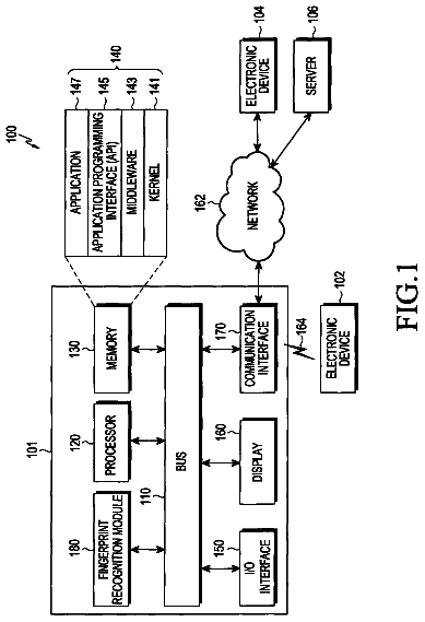
Sheet 1 of 12 from the published document. All sheets in the USPTO PDF
A method by which a tracking apparatus tracks a target object includes: acquiring a first tree structure indicating a tracking processing order of frames, each frame including a tracking area in which the target object is located; acquiring a plurality of frame groups, each frame group consisting of two frames, and acquiring distance evaluation values of the respective frame groups; acquiring a second tree structure based on the first tree structure and the distance evaluation values; and tracking the target object based on the acquired second tree structure, wherein the distance evaluation value is determined based on at least one of locations of tracking areas included in two frames belonging to the frame group and pixel values included in the tracking areas.
1.
8 of 12 drawing sheets so far from the published document, cropped to the drawing. Every sheet is in the USPTO PDF.
What the patent claimed, word for word. All of it is now free to use.
This application claims priority from Korean Patent Application No. 10-2014-0177828, filed on Dec. 10, 2014, in the Korean Intellectual Property Office, the disclosure of which is incorporated herein by reference in its entirety.
1.
Methods and apparatuses consistent with exemplary embodiments relate to tracking a target object in a video, and more particularly, to a method and apparatus for tracking a target object by optimizing a tree structure of frames included in a video.
Techniques of tracking a target object in an image with a visual signal have been researched. However, most of the existing techniques are based on tracking algorithms based on a linear structure model. The linear structure model is simple and requires minimal computation. Thus, the linear structure model is suitable for inline tracking algorithms of processing a newly input frame based on an existing frame in real-time.
A graph model that is more complex than the linear structure model and uses more computation may be applied to offline tracking algorithms capable of tracking a target object with a sufficient time by receiving a plurality of frames and online tracking algorithms for which a time delay is accepted. Therefore, to increase tracking accuracy in the offline tracking algorithms and the online tracking algorithms for which a time delay is accepted, a new graph model may be developed and a method of optimizing the graph model may be employed.
Exemplary embodiments address at least the above disadvantages and other disadvantages not described above. Also, the exemplary embodiments are not required to overcome the disadvantages described above, and may not overcome any of the problems described above.
Aspects of one or more exemplary embodiments relate to a method and an apparatus for tracking a target object in an input image.
Aspects of one or more exemplary embodiments relate to a non-transitory computer-readable medium having recorded thereon a computer-readable program for executing a tracking method according to one or more exemplary embodiments.
Additional aspects will be set forth in part in the description that follows and, in part, will be apparent from the description, or may be learned by practice of the exemplary embodiments.
According to an aspect of an exemplary embodiment, there is provided a method by which a tracking apparatus tracks a target object in an image, the method including: acquiring a first tree structure indicating an order of analyzing a plurality of frames, each frame including a tracking area in which the target object is located; acquiring a plurality of frame groups, each frame group consisting of two frames, from the plurality of frames, and acquiring a distance evaluation value of each frame group; acquiring a second tree structure based on the first tree structure and the distance evaluation values; and tracking the target object based on the acquired second tree structure, wherein each distance evaluation value is determined based on at least one of locations of tracking areas included in two frames belonging to each frame group and pixel values in the tracking areas.
The first tree structure and the second tree structure may include a plurality of nodes corresponding to the plurality of frames and connection portions for connecting the nodes, and wherein the target object in each frame corresponding to each node may be tracked in a connection order to a root node by tracking the target object from the frame corresponding to the root node.
The method may include tracking the target object based on the second tree structure and selecting one of the first tree structure and the second tree structure as a new tree structure based on a result of the tracking the target object based on the second tree structure.
The acquiring of the second tree structure may include deleting a connection portion of the first tree structure and generating a new connection portion based on the distance evaluation values.
The acquiring of the second tree structure may include: acquiring a third tree structure and a fourth tree structure by truncating one of the connection portions in the first tree structure according to the distance evaluation values of first frame groups, each first frame group consisting of two frames corresponding to connected nodes in the first tree structure; and acquiring the second tree structure by connecting a node in the third tree structure and a node in the fourth tree structure according to distance evaluation values of second frame groups, each second frame group consisting of a frame in the third tree structure and a frame in the fourth tree structure.
The acquiring of the third tree structure and the fourth tree structure may include determining truncation probabilities of the connection portions of the first tree structure according to the distance evaluation values of the first frame groups, and truncating at least one of the connection portions based on the determined truncation probabilities, and the acquiring of the second tree structure may include determining connection probabilities according to the distance evaluation values of the second frame groups, and connecting a node in the third tree structure and a node in the fourth tree structure based on the connection probabilities.
The acquiring of the distance evaluation values may include dividing a tracking area of a first frame of each frame group into a predetermined number of first divided areas, acquiring second areas matched with the first divided areas of the first frame from a second frame of each frame group, and acquiring a distance evaluation value based on locations of the second divided areas and a location of the tracking area.
The selecting may include: determining a tree energy based on a dissimilarity between tracking areas included in two frames in the second tree structure; determining an acceptance ratio for determining a probability that the second tree structure is selected as the new tree structure, based on the tree energy of the first tree structure and the tree energy of the second tree structure; and selecting the new tree structure from the first tree structure and the second tree structure based on the acceptance ratio.
The tracking of the target object may include tracking the target object according to the first tree structure acquired by iterating the acquiring of the first tree structure, the acquiring of the distance evaluation values, the acquiring of the second tree structure, and the selecting of the first tree structure.
According to an aspect of another exemplary embodiment, there is provided a tracking apparatus for tracking a target object in an image, the tracking apparatus including: a first tree structure acquirer configured to acquire a first tree structure indicating an order of analyzing a plurality of frames, each frame including a tracking area in which the target object is located; a distance evaluation value acquirer configured to acquire a plurality of frame groups, each frame group consisting of two frames, from the plurality of frames, and acquire a distance evaluation value of each frame group; a second tree structure determiner configured to acquire a second tree structure based on the first tree structure and the distance evaluation values; and a tracker configured to track the target object based on the acquired second tree structure, wherein each distance evaluation value is determined based on at least one of locations of tracking areas included in two frames belonging to each frame group and pixel values in the tracking areas.
The first tree structure and the second tree structure may include a plurality of nodes corresponding to the plurality of frames, and a plurality of connection portions configured to connect the nodes, and wherein the target object in each frame corresponding to each node may be tracked in a connection order to a root node by tracking the target object from the frame corresponding to the root node.
The apparatus may include a first tree structure selector configured to track the target object based on the second tree structure and select one of the first tree structure and the second tree structure as a new tree structure based on a result of the tracking the target object based on the second tree structure.
The second tree structure determiner may be configured to acquire the second tree structure by deleting a connection portion of the first tree structure and generating a new connection portion based on the distance evaluation values.
The second tree structure determiner may be further configured to acquire a third tree structure and a fourth tree structure by truncating one of the connection portions in the first tree structure according to the distance evaluation values of first frame groups, each first frame group consisting of two frames corresponding to connected nodes in the first tree structure, and acquire the second tree structure by connecting a node in the third tree structure and a node in the fourth tree structure according to distance evaluation values of second frame groups, each second frame group consisting of a frame in the third tree structure and a frame in the fourth tree structure.
The second tree structure determiner may be further configured to: acquire the third tree structure and the fourth tree structure by determining truncation probabilities of the connection portions of the first tree structure according to the distance evaluation values of the first frame groups, and truncating at least one of the connection portions based on the determined truncation probabilities; and acquire the second tree structure by determining connection probabilities according to the distance evaluation values of the second frame groups, and connecting a node in the third tree structure and a node in the fourth tree structure based on the connection probabilities.
The distance evaluation value acquirer may be configured to divide a tracking area of a first frame of each frame group into a predetermined number of first divided areas, acquire second areas matched with the first divided areas of the first frame from a second frame of each frame group, and acquire a distance evaluation value based on locations of the second divided areas and a location of the tracking area.
The first tree structure selector may be configured to: determine a tree energy based on a dissimilarity between tracking areas included in two adjacent frames in the second tree structure, determine an acceptance ratio for determining a probability that the second tree structure may be selected as the new tree structure, based on the tree energy of the first tree structure and the tree energy of the second tree structure, and select the new first tree structure from the first tree structure and the second tree structure based on the acceptance ratio.
The tracker may be configured to track the target object according to the first tree structure acquired by iterating functions of the first tree structure acquirer, the distance evaluation value acquirer, the second tree structure determiner, and the first tree structure selector.
According to an aspect of another exemplary embodiment, there is provided a method of tracking a target object in an image, the method including: obtaining a first tree structure indicating an order of analyzing a plurality of frames, each frame including a tracking area in which the target object is located; obtaining a plurality of frame groups, wherein each frame group includes a pair of adjacent frames; determining a distance evaluation value for each frame group that corresponds to a similarity between a first frame and a second frame in the frame group; obtaining a second tree structure based on the distance evaluation value of each frame group and the first tree structure; tracking the target object according to the obtained second tree structure.
These and/or other aspects will become apparent and more readily appreciated from the following description of one or more exemplary embodiments, taken in conjunction with the accompanying drawings in which:
FIG. 1 illustrates a block diagram of an apparatus for tracking a target object in a video, according to an exemplary embodiment;
FIGS. 2A and 2B illustrate existing methods of tracking a target object;
FIG. 3 illustrates an existing method of tracking a target object;
FIGS. 4A to 4C illustrate a method of proposing a new tree structure from an existing tree structure, according to an exemplary embodiment;
FIGS. 5 and 6 illustrate a method of calculating tree energy to determine efficiency of the new tree structure, according to an exemplary embodiment;
FIG. 7 illustrates a flowchart of a method of tracking a target object in a video, according to an exemplary embodiment;
FIG. 8 illustrates a flowchart of a method of tracking a target object in a video, according to another exemplary embodiment; and
FIG. 9 illustrates a flowchart of a method of tracking a target object in a video, according to another exemplary embodiment.
Reference will now be made in detail to exemplary embodiments, which are illustrated in the accompanying drawings, wherein like reference numerals refer to like elements throughout. Exemplary embodiments may have different forms and should not be construed as being limited to the descriptions set forth herein. Accordingly, exemplary embodiments are merely described below, by referring to the figures, to explain aspects of exemplary embodiments. As used herein, the term “and/or” includes any and all combinations of one or more of the associated listed items. Expressions such as “at least one of,” when preceding a list of elements, modify the entire list of elements and do not modify the individual elements of the list.
In the present disclosure, the term “tree structure” may indicate one of the structures of connecting frames. The tree structure includes nodes corresponding to the frames and connection portions for connecting the nodes. A connection portion is marked in an arrow shape to indicate that a tracking process of a target object from an upper node to a lower node is performed. Each upper node may have one or more lower nodes, but each lower node should have one upper node. In addition, nodes in a same level cannot be connected to each other. Therefore, nodes including the uppermost node and a plurality of lower nodes are connected in a tree shape.
When a target object in an image is tracked based on a tree structure, the target object is tracked from a frame corresponding to a root node to a frame corresponding to an upper node and frames corresponding to lower nodes according to a direction mark indicated in connection portions.
FIG. 1 illustrates a block diagram of an apparatus 100 for tracking a target object in a video, according to an exemplary embodiment.
The apparatus 100 may include a first tree structure acquisition unit 110 (e.g., first tree structure acquirer), a distance evaluation value acquisition unit 120 (e.g., distance evaluation value acquirer), a second tree structure determination unit 130 (e.g., second tree structure determiner), a tree structure selection unit 140 (e.g., tree structure selector), and a tracking unit 150 (e.g., tracker).
Although the first tree structure acquisition unit 110 and the distance evaluation value acquisition unit 120 are shown as separate components in FIG. 1 , the first tree structure acquisition unit 110 and the distance evaluation value acquisition unit 120 may be integrated and implemented as a single component according to one or more exemplary embodiments. Also, the second tree structure determination unit 130 may also be integrated with at least one of the first tree structure acquisition unit 110 and the distance evaluation value acquisition unit 120 .
Although the first tree structure acquisition unit 110 , the distance evaluation value acquisition unit 120 , the second tree structure determination unit 130 , the tree structure selection unit 140 , and the tracking unit 150 are located inside the apparatus 100 in FIG. 1 , devices in charge of the respective functions of the first tree structure acquisition unit 110 , the distance evaluation value acquisition unit 120 , the second tree structure determination unit 130 , the tree structure selection unit 140 , and the tracking unit 150 may not be physically adjacent. Therefore, according to one or more exemplary embodiments, the first tree structure acquisition unit 110 , the distance evaluation value acquisition unit 120 , the second tree structure determination unit 130 , the tree structure selection unit 140 , and the tracking unit 150 may be physically separated. The apparatus 100 of FIG. 1 is not limited to a physical device. For example, some of the functions of the apparatus 100 may be implemented by software and/or hardware.
The first tree structure acquisition unit 110 acquires a first tree structure indicating an order of analyzing frames including tracking areas in which the target object is located.
The distance evaluation value acquisition unit 120 acquires a plurality of frame groups, each consisting of two frames, from the frames and acquires a distance evaluation value predicted as a distance between tracking areas of two frames belonging to a frame group for each of the plurality of frame groups. Each of the frame groups includes two frames and has one distance evaluation value.
For example, the distance evaluation value acquisition unit 120 divides a tracking area of a first frame among first and second frames belonging to a frame group into a predetermined number of first divided areas. The distance evaluation value acquisition unit 120 acquires second divided areas matched with the first divided areas of the first frame from the second frame. A distance evaluation value may be calculated based on locations of the acquired second divided areas and a location of the tracking area of the first frame.
The distance evaluation value acquisition unit 120 may acquire the calculated distance evaluation value. Therefore, the distance evaluation value acquisition unit 120 may acquire a pre-calculated distance evaluation value when a process of optimizing the first tree structure for the same frames is iterated, thereby reducing an amount of computation.
The distance evaluation value acquisition unit 120 may determine a representative frame among frames including similar tracking areas and acquire a plurality of representative frame groups, each consisting of two representative frames. Thereafter, the distance evaluation value acquisition unit 120 may acquire distance evaluation values only for the representative frame groups. For example, when tracking areas of first to 20.sup.th frames are similar and tracking areas of 21.sup.st to 40.sup.th frames are similar, the distance evaluation value acquisition unit 120 may determine the first frame as a representative frame of the first to 20.sup.th frames and determine the 21.sup.st frame as a representative frame of the 21.sup.st to 40.sup.th frames. Thereafter, the distance evaluation value acquisition unit 120 may acquire a representative frame group consisting of the first frame and the 21.sup.st frame, which are representative frames and acquire only a distance evaluation value of the acquired representative frame group. Therefore, the number of acquitted distance evaluation values is reduced, and thus, a computation amount of the distance evaluation value acquisition unit 120 decreases.
The second tree structure determination unit 130 determines a second tree structure according to the first tree structure and distance evaluation values.
In detail, the second tree structure determination unit 130 may determine the second tree structure by deleting connection portions of the first tree structure and generating new connection portions based on the distance evaluation values.
According to an exemplary embodiment, the second tree structure determination unit 130 may acquire tree structures that are different from the first tree structure, e.g., a third tree structure and a fourth tree structure, by truncating one of connection portions of the first tree structure based on distance evaluation values of first frame groups, each consisting of two frames corresponding to nodes connected by a connection portion according to the first tree structure.
Because a lower node in a tree structure is connected to only one upper node, if a connection portion is truncated, a lower node connected to the truncated connection portion is truncated from an upper node. Therefore, the uppermost node among lower nodes connected to the truncated connection portion becomes a root node of a new tree structure. Accordingly, if one connection portion is truncated, two tree structures are generated.
The second tree structure determination unit 130 may select the largest distance evaluation value among the distance evaluation values of the first frame groups and truncate a connection portion corresponding to the selected distance evaluation value. The larger the distance evaluation value, the higher a probability that tracking areas of two frames belonging to a frame group corresponding to the distance evaluation value are dissimilar to each other. Therefore, when tracking areas are dissimilar to each other, an error due to the dissimilarity of the tracking areas may be propagated to a tracking process in a lower node. Therefore, a connection portion corresponding to a large distance evaluation value may be truncated to prevent propagation of an error due to dissimilarity of tracking areas.
The second tree structure determination unit 130 may determine the second tree structure by truncating a connection portion of the first tree structure based on distance evaluation values to divide the first tree structure into the third tree structure and the fourth tree structure and then connecting one of nodes in the third tree structure and one of nodes in the fourth tree structure according to distance evaluation values of second frame groups, each consisting of one of frames in the third tree structure and one of frames in the fourth tree structure.
The second tree structure determination unit 130 may select the smallest one of the distance evaluation values of the second frame groups and generate a connection portion between one of the nodes in the third tree structure and one of the nodes in the fourth tree structure, which correspond to the selected distance evaluation value. The smaller a distance evaluation value, the higher a probability that tracking areas of two frames belonging to a frame group corresponding to the distance evaluation value are similar to each other. Therefore, when a connection portion for connecting nodes corresponding to frames having similar tracking areas is generated, an error due to dissimilarity of tracking areas may decrease. Accordingly, the second tree structure that is more efficient than the first tree structure may be generated by generating a connection portion between one of the nodes in the third tree structure and one of the nodes in the fourth tree structure, which correspond to the smallest distance evaluation value.
The connection portion to be truncated and the connection portion to be connected may be statistically selected.
According to an exemplary embodiment, the second tree structure determination unit 130 may calculate truncation probabilities of the connection portions of the first tree structure based on the distance evaluation values of the first frame groups and truncate a connection portion determined according to the truncation probabilities.
The second tree structure determination unit 130 may determine the second tree structure by calculating connection probabilities of the frames of the second frame groups based on the distance evaluation values of the second frame groups and connecting one of the nodes in the third tree structure and one of the nodes in the fourth tree structure, for which a connection portion is to be generated according to the connection probabilities.
The second tree structure determination unit 130 may determine various second tree structures by using the truncation probabilities and the connection probabilities.
A method by which the second tree structure determination unit 130 determines the second tree structure will be described in more detail with reference to FIGS. 4A to 4C .
The tree structure selection unit 140 tracks the target object based on the second tree structure and selects one of the first tree structure and the second tree structure based on the tracking result based on the second tree structure.
According to an exemplary embodiment, the tree structure selection unit 140 may determine tree energy based on dissimilarity between tracking areas included in two adjacent frames in the second tree structure. The tree structure selection unit 140 may select a tree structure having lower tree energy from the first tree structure and the second tree structure with a relatively high probability according to the determined tree energy. The tree energy will be described below with reference to FIGS. 5 and 6 .
According to an exemplary embodiment, the tree structure selection unit 140 may determine the selected tree structure as a new first tree structure. Thereafter, the first tree structure acquisition unit 110 may acquire the new first tree structure determined by the tree structure selection unit 140 . Thereafter, the apparatus 100 may determine another new first tree structure by performing the functions of the distance evaluation value acquisition unit 120 , the second tree structure determination unit 130 , and the tree structure selection unit 140 . The first tree structure may be iteratively acquired by the first tree structure acquisition unit 110 , and a new first tree structure may be generated by the tree structure selection unit 140 based on the first tree structure. The first tree structure may be optimized by iterating this process.
The tracking unit 150 tracks the target object according to the selected tree structure.
The target object tracking process described above may be performed by the apparatus 100 .
FIGS. 2A and 2B illustrate an existing method of tracking a target object.
FIG. 2A illustrates a linear model 200 among methods of tracking a target object.
In the linear model 200 , frames included in an image are arranged in an order of time. Therefore, when a frame A is a first frame, a target object in the frame A is tracked first of all. Thereafter, the target object in a frame B, that is a next frame of the frame A, is tracked based on at least one of a location of a tracking area in which the target object in the frame A is located and pixel values included in the tracking area.
In the linear model 200 , if there is a significant difference between a tracking area in which the target object in a previous frame and a tracking area in which the target object in a current frame with respect to locations of the tracking areas and pixels included in the tracking areas, the target object in a current frame is not tracked. For example, if a portion of the target object is hidden by another object in the current frame, a tracking apparatus cannot track, in the current frame, the target object in the previous frame. In addition, if the target object in the current frame is darker than the target object in the previous frame, the tracking apparatus may recognize the target object in the current frame as different from the target object in the previous frame.
That is, in the linear model 200 , if there is a sudden change in pixels included in an area where the target object is located, an error may occur, and the error may be propagated to a next frame.
FIG. 2B illustrates a high-order Markov model 250 among methods of tracking a target object.
In the high-order Markov model 250 , one frame is connected to a plurality of frames in which the target object is tracked. For example, in the high-order Markov model 250 of FIG. 2B , a frame F is connected to frames A and C, and a frame D to be tracked lastly is connected to frames A, B, C, E, and F.
For the frame F, the target object in the frame F is tracked based on locations of tracking areas where the target object in the frames A and C is located, pixels included in the tracking areas, and the like. Likewise, for the frame D, the target object in the frame D is tracked based on at least one of locations of tracking areas where the target object in the frames A, B, C, E, and F is located and pixels included in the tracking areas.
In detail, for the frame F, an average or a weighted average of pixels included in the tracking areas of the frames A and C may be used, and for the frame D, an average or a weighted average of pixels included in the tracking areas of the frames A, B, C, E, and F may be used.
In the high-order Markov model 250 , unlike the linear model 200 , the target object is tracked based on a plurality of frames. Thus, the high-order Markov model 250 causes less error than the linear model 200 . However, a frame in which a portion of a target object is hidden by another object and a frame in which the target object is darker than that in other frames are not excluded to track the target object in a current frame. Accordingly, the high-order Markov model 250 may propagate an error to a next frame if the error occurs in a previous frame.
FIG. 3 illustrates an existing method of tracking a target object. In detail, FIG. 3 illustrates a problem of the linear model 200 of FIG. 2A .
In the linear model 200 , a tracking apparatus detects an area that is similar to a tracking area of a previous frame from a current frame, based on a location of the tracking area where a target object 302 in the previous frame is located. For example, in frames A, B, C, D, E, and F, ( 310 , 320 , 330 , 340 , 350 , and 360 ), a car that is the target object 302 is shown. The frames A and B ( 310 and 320 ) have similar locations of tracking areas 312 and 322 where the target object 302 is located, and similar pixels included in the tracking areas 312 and 322 , respectively. Accordingly, the tracking area 322 of the frame B ( 320 ) is easily detected from the frame A ( 310 ).
However, in the frame C ( 330 ), a motorcycle 304 hides a portion of the target object 302 . Accordingly, the tracking apparatus cannot detect an area that is similar to the tracking area 322 of the frame B ( 320 ) from the frame C ( 330 ). Therefore, the tracking apparatus cannot detect the target object 302 from the frame C ( 330 ).
This error is propagated to the frames D, E, and F ( 340 , 350 , and 360 ). Therefore, even though the motorcycle 304 does not hide the target object 302 in the frames D, E, and F ( 340 , 350 , and 360 ), the tracking apparatus cannot detect the target object 302 included in the frames D, E, and F ( 340 , 350 , and 360 ).
In the high-order Markov model 250 of FIG. 2B , a target object is tracked by referring to a plurality of frames, and thus, less error occurs compared to the linear model 200 . However, as described above, a frame in which a portion of a target object is hidden by another object and a frame in which the target object is darker than that in other frames, and the like, are not excluded.
FIGS. 4A to 4C illustrate a method of proposing a new tree structure 480 from an existing tree structure 400 .
A method of acquiring the new tree structure 480 includes a connection portion truncation operation, a connection portion generation operation, and a connection portion change operation.
FIG. 4A illustrates the connection portion truncation operation. In FIG. 4A , nodes A, B, C, D, E, and F ( 410 , 420 , 430 , 440 , 450 , and 460 ) form a linearly connected tree structure. The nodes A, B, C, D, E, and F ( 410 , 420 , 430 , 440 , 450 , and 460 ) correspond to frames A, B, C, D, E, and F, respectively. Connection portions 401 , 402 , 403 , 404 , and 405 for connecting nodes exist between two nodes, and in the connection portion truncation operation, one of the connection portions 401 , 402 , 403 , 404 , and 405 is truncated.
The connection portion truncated in the connection portion truncation operation is determined based on a distance evaluation value between two frames corresponding to two nodes connected through each connection portion. The distance evaluation value may be calculated in a method described below. For example, a tracking area of a first frame of two frames is divided into a predetermined number of first divided areas. Thereafter, second divided areas matched with the first divided areas of the first frame are acquired from a second frame of the two frames. Thereafter, a distance evaluation value may be determined by Equation 1 below based on locations of the second divided areas and a location of the tracking area of the first frame.
d ( i , j ) ≡ median m ( .Math. v i m - f P M ( v i m ; y j ) .Math. ) ( 1 )
In Equation 1, d(i,j) denotes a distance evaluation value between a frame i and a frame j, v.sub.i.sup.m denotes a location of an mth first divided area of the frame i, f.sub.PM(v.sub.i.sup.m;y.sub.j) denotes a second divided area of the frame j, which corresponds to v.sub.i.sup.m, and ∥v.sub.i.sup.m−f.sub.PM(v.sub.i.sup.m;y.sub.j)∥ denotes a distance vector between v.sub.i.sup.m and f.sub.PM(v.sub.i.sup.m;y.sub.j). Therefore,
median m ( .Math. v i m - f P M ( v i m ; y j ) .Math. ) denotes a median value of distance vectors between m first divided areas and m second divided areas.
Accordingly, even though an area perfectly corresponding to an overall tracking area of the first frame may not exist in the second frame, the distance evaluation value may be calculated using the second divided areas corresponding to the first divided areas into which the first frame is divided. The distance evaluation value obtained by the method described above is not an actual displacement of a target object but a displacement predicted by a tracking apparatus.
After obtaining distance evaluation values respectively corresponding to the connection portions 401 , 402 , 403 , 404 , and 405 , a truncation probability of each of the connection portions 401 , 402 , 403 , 404 , and 405 is obtained based on the distance evaluation values. The larger a distance evaluation value, the higher a probability that an error occurs in tracking of the target object in the second frame based on the first frame. Therefore, the truncation probability is determined such that a connection portion of which a distance evaluation value is larger is truncated. The truncation probability may be determined by Equation 2.
P delete ( i , j ) = exp ( d ( i , j ) ) Σ ( a , b ) ∈ .Math. exp ( d ( a , b ) ) ( i , j ) ∈ .Math. ( 2 )
In Equation 2, P.sub.delete(i,j) denotes a truncation probability that a connection portion between nodes corresponding to frames i and j is truncated, ϵ denotes a set of frame groups to which two frames corresponding to nodes adjacent by the connection portion belong in a tree structure. According to Equation 2, P.sub.delete(i,j) is proportional to a value for which a base is a natural constant and an exponent is a distance evaluation value. Therefore, a difference in P.sub.delete(i,j) is much larger than a difference in a distance evaluation value.
If truncation probabilities respectively corresponding to the connection portions 401 , 402 , 403 , 404 , and 405 are determined, a connection portion to be truncated is determined based on the truncation probabilities. Because the connection portion to be truncated is determined based on the truncation probabilities, a connection portion for which a distance evaluation value is the largest is not necessarily determined as the connection portion to be truncated. Therefore, a connection portion for which a distance evaluation value is small may be truncated.
According to one or more exemplary embodiments, it may be determined that a connection portion corresponding to the largest distance evaluation value is truncated without obtaining truncation probabilities.
In FIG. 4A , the connection portion 402 between the node B ( 420 ) and the node C ( 430 ) is truncated according to the method described above. Therefore, the existing tree structure 400 is divided into a tree structure consisting of the node A ( 410 ) and the node B ( 420 ) and a tree structure consisting of the nodes C, D, E, and F ( 430 , 440 , 450 , and 460 ).
FIG. 4B illustrates the connection portion generation operation.
In the connection portion generation operation, two tree structures are connected. When the two tree structures are referred to as the third and fourth tree structures, one of nodes in the third tree structure is connected to one of nodes in the fourth tree structure. In the connection portion generation operation, nodes to be connected by a newly generated connection portion are determined based on a distance evaluation value of a frame group corresponding to nodes. The smaller a distance evaluation value, the lower a probability that an error occurs in tracking of a target object. Therefore, a connection probability is determined such that a connection portion is generated between nodes corresponding to a frame group for which a distance evaluation value is small. The connection probability may be determined by Equation 3.
P add ( i , j ) = exp ( - d ( i , j ) ) Σ ( a , b ) ∈ .Math. _ exp ( - d ( a , b ) ) ( i , j ) ∈ .Math. _ ( 3 )
In Equation 3, P.sub.add(i,j) denotes a connection probability that a connection portion is generated between nodes corresponding to frames i and j, and ϵ denotes a set of frame groups to which two frames corresponding to two nodes which are not connected to each other belong in a tree structure. According to Equation 3, P.sub.add(i,j) is proportional to a value for which a base is a natural constant and an exponent is a negative value of a distance evaluation value. Therefore, a difference in P.sub.add(i,j) is much larger than a difference in a distance evaluation value.
When connection probabilities corresponding to frame groups in ϵ , a connection portion is generated between two nodes corresponding to a frame group determined based on the connection probabilities. Because the connection portion to be generated is arbitrarily determined based on the connection probabilities, it is not necessarily determined that a connection portion is generated for a frame group for which a distance evaluation value is the smallest. Therefore, a connection portion for which a distance evaluation value is large may be generated.
According to one or more exemplary embodiments, it may be determined that a connection portion corresponding to the smallest distance evaluation value is generated without obtaining connection probabilities.
In FIG. 4B, 8 connection portions 411 , 412 , 413 , 414 , 415 , 416 , 417 , and 418 may be generated between the third tree structure and the fourth tree structure. Finally, the connection portion 412 is generated between the node A ( 410 ) in the third tree structure and the node D 440 in the fourth tree structure. Accordingly, the third tree structure is connected to the fourth tree structure.
FIG. 4C illustrates the connection portion change operation.
A direction of each connection portion in the structure connected in the connection portion generation operation may be changed from an upper node to a lower node such that the structure connected in the connection portion generation operation becomes a tree structure. As a result of the connection portion change operation, the new tree structure 480 is acquired.
The description continues in the full USPTO document.
About 6,686 words. The USPTO PDF has it with every drawing.
Fees are due 3.5, 7.5 and 11.5 years after grant. This patent expired on March 20, 2026, so the fee marked "not paid" was the one that went unpaid.
METHOD AND APPARATUS FOR TRACKING TARGET OBJECT
Filed Dec 2015 · published Jun 2016Method and apparatus for tracking target object
Filed Dec 2015 · granted Mar 2018Earlier publications, parents and continuations. None of them can still be enforced, or this patent would not be listed.
Prior art cited by the examiner or applicant. Useful when you check your own idea for novelty.
Everything on this page comes from the documents linked above.


